Rhotheta RT-800 Camera Accessories Manuals
Manuals and User Guides for Rhotheta RT-800 Camera Accessories. We have 4 Rhotheta RT-800 Camera Accessories manuals available for free PDF download: User Manual, User Manual, Installation & Operation, Installation And Configuration Manual

Rhotheta RT-800 User Manual (192 pages)
Brand: Rhotheta
|
Category: Marine Equipment
|
Size: 14 MB
Table of Contents
Advertisement

Rhotheta RT-800 User Manual, Installation & Operation (75 pages)
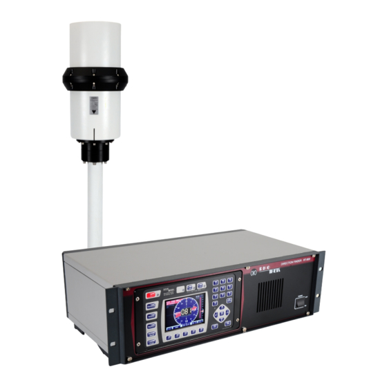
Wideband Precision Direction Finder
Brand: Rhotheta
|
Category: Marine Equipment
|
Size: 2 MB
Table of Contents

Rhotheta RT-800 Installation And Configuration Manual (36 pages)
Wideband Precision Direction Finder
Brand: Rhotheta
|
Category: Marine Equipment
|
Size: 3 MB
Table of Contents
Advertisement

Rhotheta RT-800 Installation And Configuration Manual (32 pages)
Brand: Rhotheta
|
Category: Camera Accessories
|
Size: 7 MB