Sign In
Upload
Manuals
Brands
REXROTH Manuals
Industrial Equipment
Sytronix FcP 5020
REXROTH Sytronix FcP 5020 Manuals
Manuals and User Guides for REXROTH Sytronix FcP 5020. We have
1
REXROTH Sytronix FcP 5020 manual available for free PDF download: Operating Instructions Manual
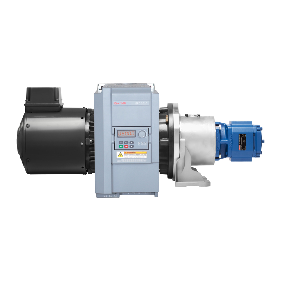
REXROTH Sytronix FcP 5020 Operating Instructions Manual (204 pages)
Frequency-controlled pump drive system
Brand:
REXROTH
| Category:
Industrial Equipment
| Size: 8 MB
Table of Contents
Table of Contents
3
1 About this Documentation
9
Validity of the Documentation
9
Required and Amending Documentation
10
Representation of Information
12
Consistency
12
Safety Instructions
12
Symbols
13
Abbreviations
13
2 Safety Instructions
15
General Information on this Chapter
15
Intended Use
15
Improper Use
15
Qualification of Personnel
16
General Safety Instructions
16
Product- and Technology-Dependent Safety Instructions
17
Obligations of the Machine End-User
19
3 Safety Instructions for Electric Drives and Controls
21
Definitions of Terms
21
General Information
23
Using the Safety Instructions and Passing Them on to Others
23
Requirements for Safe Use
23
Hazards by Improper Use
24
Instructions with Regard to Specific Dangers
25
Protection against Contact with Electrical Parts and Housings
25
Protective Extra-Low Voltage as Protection against Electric Shock
26
Protection against Dangerous Movements
27
Protection against Electromagnetic and Magnetic Fields During Operation and Mounting
28
Protection against Contact with Hot Parts
29
Protection During Handling and Mounting
29
Battery Safety
30
Protection against Pressurized Systems
30
General Warnings of Damage to Property and Damage to the Product
31
Explanation of Signal Words and the Safety Alert Symbol
33
4 About this Product
35
Product Description
35
Component Overview
36
System Components Example
36
Installation of EFC for Fcp in a Cabinet
37
Type Code and Label of EFC 5610 for Fcp 5020
38
Frequency Converter Type Code Description
38
Fcp 5020 ASF Type Code Description
40
Version Matching Table
41
Input and Output Allocation at the Frequency Converter
42
Standard Wiring Diagram
42
Control Terminals Description
43
Digital Inputs
43
Analog Inputs
43
Digital Outputs
44
Analog Outputs
44
Power Terminal
44
Control Terminals
46
Control Terminals Figure
46
5 Transport and Storage
47
6 Assembly and Installation
49
General Information
49
Unpacking
49
Installation Conditions
49
Installation Conditions for Motor Pump Unit
49
Installation Conditions for Frequency Converter and Additional Components
50
Assembling the Fcp System
51
Mechanically Connecting the Motor Pump Unit
51
Hydraulically Connecting the Motor Pump Unit
51
Connection Technique
52
General Notes
52
Power Connection
54
Connect the Motor Fan
58
Connection EFC 5610 for Fcp 5020
59
Digital Input NPN / PNP Wiring
59
Digital Output Do1A, Do1B Load Pull-Up / Pull-Down Wiring
60
Relay Output Terminals
60
Connection of the Pressure Transducer
62
Electronic Component Assembly and Installation in Control Cabinet
63
7 Commissioning of Sytronix Fcp 5020 System
65
Introduction and Basics
65
Application Type
65
Functional Characteristics
66
Getting Started with Fcp 5020
67
Notes on Commissioning
67
Hydraulic System Preparation
67
Electric Hardware Connection Preparation
68
Operating Preparation
68
Relevant Parameters
69
Starting with Fcp 5020 Dialog
70
Converter I/O Configuration
73
Analog Input AI1
73
Quick Configuration for Rexroth HM20 Pressure Sensor
76
Analog Input AI2
78
Analog Output AO1
79
Digital Input
80
Digital and Relay Output
81
Quick Configuration for Rexroth MOT-FC_HOY Motor
82
First Commissioning
85
Commissioning (Advanced)
87
Overview of Main Functions
87
Pq Controller Parameter Setting
89
Overview and Introduction
89
Enhanced Parameter Setting
96
Overview and Introduction
96
Easy Command Setting: Internal Parameter, Selectable Pressure Command
96
Control Parameter Selection: Free Selectable Parameter Sets (2 Sets)
97
Switching Integral Time Ti
98
Minimum Flow and Minimum Pressure
99
Extension Functions
100
Pump Extended Function
100
Master / Slave Function
101
Sleep / Wake Function
103
Two Points / Double Pump Control
105
Pressure Drop / Overshoot Compensation
107
Pump Power Limitation
108
Hydraulic Soft Start and Separate Acceleration Ramp
109
Protection Function
110
Condition Monitoring and Protection
110
Overview
111
Pressure Sensor Failure Detection
111
Actual Pressure Monitoring
114
Oil Change Warning / Error Function
115
Pressure and Flow Command Limit
116
Pump Thermal Protection
117
Sensor Monitoring
118
Cytropac Configuration
119
Overview
119
Load Cytropac Configuration
119
Cytropac Sensor Monitoring
119
LED Flash Showing Converter Status
120
Mycro Configuration
121
Overview
121
Load Mycro Configuration
121
Mycro Function Description
125
Fieldbus Communication
126
Brief Introduction
126
Frequency Converter Parameter Address
126
Loading Process Data Via Dialog
128
Additional Notes
130
Motor Thermal Model Protection
130
Motor Thermal Protection with Temperature Sensor
131
Commissioning Tool
132
Fcp 5020 Parameter List
133
Terminology and Abbreviation in Parameter List
133
Group F1: Quick Start Parameter
134
Group F2: Input and Output Parameter
136
Group F3: P/Q PID Parameter
139
Group F4: System Protection and Pump Function Parameter
140
Auto-Modified EFC Parameters in Fcp Initialization
142
Changed Setting Parameter by Load Cytropac Configuration
143
Monitoring Parameter
145
EFC Parameter List
146
Terminology and Abbreviation in Parameter List
146
Group B: System Parameters
146
B0: Basic System Parameters
146
Group C: Power Parameters
147
C0: Power Control Parameters
147
C1: Motor and System Parameters
149
C2: V/F Control Parameters
150
C3*: Vector Control Parameters
151
Group E: Function Control Parameters
152
E0: Set Point and Control Parameters
152
E1: Input Terminal Parameters
155
E2: Output Terminal Parameters
158
E5: Extended Function Parameters
160
E8: Standard Communication Parameters
161
E9: Protection and Error Parameters
162
Group F0: ASF Parameters
164
Group H: Extension Card Parameters
165
H0: Extension Card General Parameters
165
H1: Communication Card Parameters
166
H8: I/O Card Parameters
168
H9: Relay Card Parameters
171
Group U: Panel Parameters
172
U0: General Panel Parameters
172
U1: LED Panel Parameters
172
U2: LCD Panel Parameters
173
Group D0: Monitoring Parameters
176
8 Operation
179
General Information
179
Modes
179
Standby / Parameter Mode
179
Operating Mode
179
Error Mode
179
9 Maintenance
181
System Overview
181
Drive Controllers
181
Motor-Pump Unit
181
10 Decommissioning
182
11 Disassembly and Replacement
183
Disassembly
183
Preparing for Disassembly
183
Disassembling the Hydraulic Product
183
Motor-Pump Unit
184
Drive Controller
184
12 Environmental Protection and Disposal
185
Environmental Protection
185
Disposal
185
13 Extension and Modification
187
14 Troubleshooting
189
Display of LED Characters
189
Status Code
189
EFC Warning Code
189
EFC Error Code
190
Error 1 (OC-1): Overcurrent at Constant Speed
190
Error 2 (OC-2): Overcurrent During Acceleration
190
Error 3 (OC-3): Overcurrent During Deceleration
190
Error 4 (OE-1): Overvoltage at Constant Speed
191
Error 5 (OE-2): Overvoltage During Acceleration
191
Error 6 (OE-3): Overvoltage During Deceleration
191
Error 7 (OE-4): Overvoltage During Stop
191
Error 8 (UE-1): Undervoltage During Run
191
Error 9 (SC): Surge Current or Short Circuit
192
Error 10 (IPH.L): Input Phase Loss
192
Error 11 (OPH.L): Output Phase Loss
192
Error 12 (ESS-): Soft Start Error
192
Error 20 (OL-1): Converter Overload
192
Error 21 (OH): Converter over Temperature
193
Error 22 (UH): Converter under Temperature
193
Error 23 (FF): Fan Failure
193
Error 24 (Pdr): Pump Dry
193
Error 25 (Col-): Command Value Lost
193
Error 30 (OL-2): Motor Overload
194
Error 31 (Ot): Motor over Temperature
194
Error 32 (T-Er): Motor Parameter Tuning Error
194
Error 33 (Ade-): Synchronous Motor Angle Detection Error
194
Error 38 (Aibe): Analog Input Broken Wire Detection
195
Error 39 (EPS-): DC_IN Power Supply Error
195
Error 40 (Dir1): Forward Running Lock Error
195
Error 41 (Dir2): Reverse Running Lock Error
195
Error 42 (E-St): Terminal Error Signal
195
Error 43 (FFE-): Firmware Version Mismatch
195
Error 44 (Rs-): Modbus Communication Error
196
Error 45 (E.par): Parameter Settings Invalid
196
Error 46 (U.par): Unknown Parameter Restore Error
196
Error 48 (Ida-): Internal Communication Error
196
Error 49 (Idp-): Internal Parameter Error
196
Error 50 (Ide-): Converter Internal Error
196
Error 51 (Ocd-): Extension Card Internal Error
196
Error 52 (Occ): Extension Card Pdos Configuration Error
196
Error 53 (Fdi-): no Valid Process Data
197
Error 54 (Pce-): Remote Control Communication Error
197
Error 55 (Pbre): Parameter Backup / Restore Error
197
Error 56 (Pref): Parameter Restore Error after Firmware Update
197
Error 60 (ASF-): Application Firmware Error
197
Error 61
197
Sytronix Warning Code
198
Sytronix Error Code
199
15 Service and Support
200
Sales and Service Network
200
Internet Contact
200
Preparation of Information
200
Index
201
Advertisement
Advertisement
Related Products
REXROTH IndraDrive Fc FCS01
REXROTH Fe Series
Rexroth FECxO2.1-7K50
Rexroth FECxO2.115K0
Rexroth FECxO2.111K0
Rexroth FECxO2.1-37K0
Rexroth FECx02.1-45K0
Rexroth FECxO2.1-75K0
Rexroth FECx02.1-110K
Rexroth FECxO2.1-132K
REXROTH Categories
Engine
Controller
Control Unit
DC Drives
Media Converter
More REXROTH Manuals
Login
Sign In
OR
Sign in with Facebook
Sign in with Google
Upload manual
Upload from disk
Upload from URL