Sign In
Upload
Manuals
Brands
Rexroth Manuals
Engine
MAD100B-MAD100B-0050
User Manuals: Rexroth MAD100B-MAD100B-0050 Servo Motor
Manuals and User Guides for Rexroth MAD100B-MAD100B-0050 Servo Motor. We have
1
Rexroth MAD100B-MAD100B-0050 Servo Motor manual available for free PDF download: Project Planning Manual
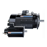
Rexroth MAD100B-MAD100B-0050 Project Planning Manual (220 pages)
Asynchronous Motors MAD/MAF
Brand:
Rexroth
| Category:
Engine
| Size: 4.63 MB
Table of Contents
Table of Contents
3
1 Introduction to the Product
9
About this Documentation
10
Additional Components
11
Feedback
11
Standards
11
2 Important Directions for Use
13
Appropriate Use
13
Introduction
13
Areas of Use and Application
14
Inappropriate Use
14
3 Safety Instructions for Electric Drives and Controls
15
Introduction
15
Explanations
15
Hazards by Improper Use
16
General Information
17
Protection against Contact with Electrical Parts
19
Protection against Electric Shock by Protective Low Voltage (PELV)
20
Protection against Dangerous Movements
21
Protection against Magnetic and Electromagnetic Fields During Operation and Mounting
23
Protection against Contact with Hot Parts
24
Protection During Handling and Mounting
24
Battery Safety
25
Protection against Pressurized Systems
25
4 Technical Data
27
Operating Modes
27
Operating Behavior
28
Technical Data Sheet for MAD100B
30
Characteristic Curves of MAD100B
31
Technical Data Sheet for MAD100C
34
Characteristic Curves of MAD100C
35
Technical Data Sheet for MAD100D
38
Characteristic Curves of MAD100D
39
Technical Data Sheet for MAD130B
42
Characteristic Curves of MAD130B
43
Technical Data Sheet for MAD130C
46
Characteristic Curves of MAD130C
47
Technical Data Sheet for MAD130D
50
Characteristic Curves of MAD130D
51
Technical Data Sheet for MAD160B
54
Characteristic Curve of MAD160B
55
Technical Data Sheet for MAD160C
57
Characteristic Curves of MAD160C
58
Technical Data Sheet for MAD180C
60
Characteristic Curves of MAD180C
61
Technical Data Sheet for MAD180D
63
Characteristic Curves of MAD180D
64
Technical Data Sheet for MAF100B
66
Characteristic Curves of MAF100B
67
Technical Data Sheet for MAF100C
70
Characteristic Curves of MAF100B
71
Technical Data Sheet for MAF100D
74
Characteristic Curves of MAF100D
75
Technical Data Sheet for MAF130B
78
Characteristic Curves of MAF130B
79
Technical Data Sheet for MAF130C
82
Characteristic Curves of MAF130C
83
Technical Data Sheet for MAF130D
86
Characteristic Curves of MAF130D
87
Technical Data Sheet for MAF160B
90
Characteristic Curves of MAF160B
91
Technical Data Sheet for MAF160C
93
Characteristic Curves of MAF160C
94
Technical Data Sheet for MAF180C
96
Characteristic Curves of MAF180C
97
Technical Data Sheet for MAF180D
99
Characteristic Curves of MAF180D
100
5 Dimension Sheets
103
Dimension Sheet for MAD100, Without Brake
103
Dimension Sheet for MAD100, with Brakes 1 and 5
104
Dimension Sheet for MAD130, Without Brake
105
Dimension Sheet for MAD130, with Brakes 1 and 5
106
Dimension Sheet for MAD160, Without Brake
107
Dimension Sheet for MAD160, with Brakes 1 and 5
108
Dimension Sheet for MAD160, with Brake 3
109
Dimension Sheet for MAD180, Without Brake
110
Dimension Sheet for MAD180, with Brakes 2 and 5
111
Dimension Sheet for MAF100, Without Brake
112
Dimension Sheet for MAF100, with Brakes 1 and 5
113
Dimension Sheet for MAF130, Without Brake
114
Dimension Sheet for MAF130, with Brakes 1 and 5
115
Dimension Sheet for MAF160, Without Brake
116
Dimension Sheet for MAF160, with Brakes 1 and 5
117
Dimension Sheet for MAF160, with Brake 3
118
Dimension Sheet for MAF180, Without Brake
119
Dimension Sheet for MAF180, with Brakes 2 and 5
120
6 Type Codes
121
Introduction
121
Definition
121
Type Code for MAD100
124
Type Code for MAD130
126
Type Code for MAD160
128
Type Code for MAD180
130
Type Code for MAF100
132
Type Code for MAF130
134
Type Code for MAF160
136
Type Code for MAF180
138
7 Accessories
141
Labyrinth Seal
141
Air-Pressure Connector Kit
142
Gearboxes
143
8 Connection Techniques
145
Notes
145
Power Connection
146
Overview
146
Power Connection Via Flange Socket
147
Flange Socket
147
Power Connection Via Terminal Box
148
Terminal Box
148
Connection Designations on the Drive Device
149
Double Cabling
150
Encoder Connection
151
Temperature Sensors
153
Holding Brake
154
Motor Cooling
154
Blower Connection
154
Connection of Liquid Cooling
155
Operating Pressure
155
Snap-On Couplings
156
9 Application Notes
157
Operating Conditions
157
Setup Elevation and Ambient Temperature
157
Humidity
158
Vibration and Shock
158
Vibration
158
Shock
159
Compatibility with Foreign Material
159
Degree of Protection
160
Design and Installation Position
161
Vertical Assembly
162
Housing Paint
163
Motor Cooling
164
Blower
164
Coolants
165
Materials Used in the Cooling System
166
Inlet Temperature of Coolant
167
Motor Temperature Overview
168
Motor Holding Brake (Option)
169
Selecting Holding Brakes
170
Dimensioning of Holding Brakes (Application)
171
Motor Encoder
173
Options
173
Compatibility
173
Accuracy/Repeatability
174
Connection of the Encoder
175
Output Shaft
175
Plain Shaft
175
Output Shaft with Key
175
Output Shaft with Seal
176
Bearing and Shaft Loads
178
Radial Load, Axial Load
178
Attachment of Drive Elements
182
Couplings
183
Helical Driving Pinion
184
Bevel Gear Pinion
184
Bearing Lifetime
185
Grease Service Life
186
Types of Bearing
189
Tips for Selection
191
Vibration Severity Class
192
Acceptances and Authorizations
193
CE Symbol
193
UR, Cur Listing
193
10 Handling and Transportation
195
Delivery Status
195
Factory Test
195
Inspection Tests by the Customer
195
Identification
196
Designation
196
Transportation and Storage
197
11 Installation
199
Safety
199
Mechanical Attachment
199
Mounting Holes
199
Preparation
200
Assembly
200
Electrical Connection
200
12 Operating Indradyn a Motors
201
Commissioning
201
Preparation
201
Execution
201
Deactivation
202
Dismantling
202
Maintenance
203
Measures
203
MAD - Motor Blower
204
MAF - Coolant Supply
205
Maintaining Holding Brakes
205
Troubleshooting
206
Excess Temperature of Motor Housing
206
High Motor Temperature Values, but Housing Temperature Is Normal
207
Motor or Rotary Table Generates Vibrations
207
Specified Position Is Not Attained
208
13 Service & Support
209
Helpdesk
209
Service-Hotline
209
Internet
209
Vor der Kontaktaufnahme
209
Kundenbetreuungsstellen
210
14 Index
215
Advertisement
Advertisement
Related Products
Rexroth MAD100B-0150
Rexroth MAD100B-0100
Rexroth MAD100B-0200
Rexroth MAD100B-0250
REXROTH MAD100
Rexroth MAD100C-0050
Rexroth MAD100C-0100
Rexroth MAD100C-0150
Rexroth MAD100C-0200
Rexroth MAD100D-0050
Rexroth Categories
Controller
Engine
DC Drives
Media Converter
Control Unit
More Rexroth Manuals
Login
Sign In
OR
Sign in with Facebook
Sign in with Google
Upload manual
Upload from disk
Upload from URL