Sign In
Upload
Manuals
Brands
RenewAire Manuals
Heater
RH-D Series
RenewAire RH-D Series Manuals
Manuals and User Guides for RenewAire RH-D Series. We have
2
RenewAire RH-D Series manuals available for free PDF download: Installation, Operation And Maintenance Manual, Installation, Operation & Maintenance Manual
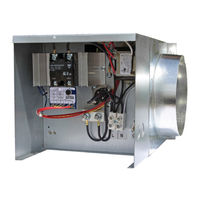
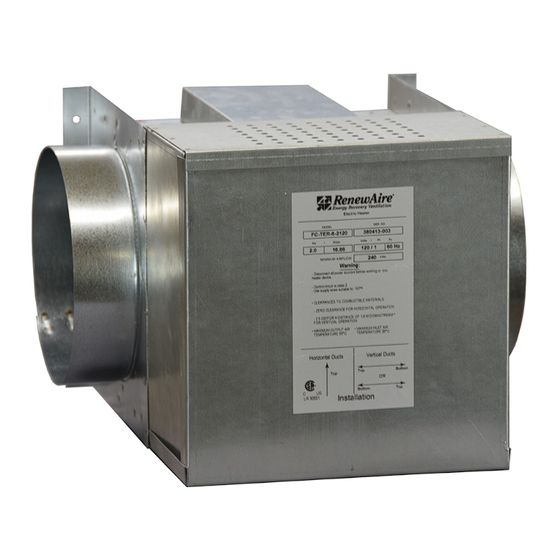
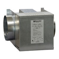
RenewAire RH-D Series Installation, Operation And Maintenance Manual (32 pages)
ELECTRIC DUCT HEATERS
Brand:
RenewAire
| Category:
Heater
| Size: 4 MB
Table of Contents
Table of Contents
5
1 Overview
8
Description
8
Applications
8
Safety Features
8
Low Air Flow Modulation/Shut off
8
Auto-Reset Thermal Cutout
8
Manual Reset Thermal Cutout
8
Maintenance
8
Airflow Direction
8
Rh-D
8
Rh-W
9
Rh-D and Rh-W Models
9
Figure 1.5.0 RH Series Configurations
9
2 Component Descriptions
10
Rh-D
10
Figure 2.1.0 RH-D Manual Reset Thermal Cutout and Output Air Temperature Sensor
10
Figure 2.1.1 RH-D Airflow Sensor and Autor Reset Thermal Cutout
10
Rh-W
11
Figure 2.1.2 RH-D Controls (Typ)
11
Figure 2.2.0 RH-W Controls (Typ)
11
CTH291 Thermostat
12
Figure 2.2.1 RH-W CTH291 Wall Thermostat (Typ)
12
3 Dimensioned Drawings
13
Rh-W and Rh-D with 6" Duct Collar
13
Rh-D and Rh-W with 8" Duct Collar
13
Figure 3.1.0 RH-D and RH-W 6" Duct Collar Dimensioned Drawing
13
Figure 3.2.0 RH-D and RH-W 8" Duct Collar Dimensioned Drawing
13
Rh-D and Rh-W with 10" Duct Collar
14
Rh-D and Rh-W with 12" Duct Collar
14
Figure 3.3.0 RH-D and RH-W 10" Duct Collar Dimensioned Drawing
14
Figure 3.4.0 RH-D 12" Duct Collar Dimensioned Drawing
14
4 Wiring Schematics
15
Rh-D 120 Vac
15
Rh-D 208/240 Vac (1, 2, 3, 4, 5, and 6 Kw)
15
Figure 4.1.0 RH-D 120 VAC Wiring Schematic
15
Figure 4.2.0 RH-D 208/240 VAC Wiring Schematic (1, 2, 3, 4, 5, 6 Kw)
15
Rh-D 240 Vac (8, 10, and 11.5 Kw)
16
Rh-W 120 Vac
16
Figure 4.3.0 RH-D 240 VAC Wiring Schematic (8, 10, 11.5 Kw)
16
Figure 4.4.0 RH-W 120 VAC Wiring Schematic
16
Rh-W 208/240 Vac (1, 2, 3, 4, 5, and 6 Kw)
17
Rh-W 240 Vac (8, 10, and 11.5 Kw)
17
Figure 4.5.0 RH-W 208/240 VAC Wiring Schematic (1, 2, 3, 4, 5, 6 Kw)
17
Figure 4.6.0 RH-W 240 VAC Wiring Schematic (8, 10, 11.5 Kw)
17
5 Unit Weights
18
Rh-D and Rh-W with 6" Duct
18
Rh-D and Rh-W with 8" Duct
18
Rh-D and Rh-W with 10" or 12" Ducts
18
6 Installation
18
Minimum Airflow Requirements
18
Installation Location
18
Unit Orientation
18
Installation Clearances
18
Figure 6.4.0 Ventilation Clearance
18
Ductwork Connections
19
Ductwork Insulation
19
Verify Airflow Direction (Rh-D Units Only)
19
Figure 6.4.2 Installation Supports
19
Figure 6.7.0 Airflow Directions
19
Connect Electric Service
20
Line Voltage Wiring Entry Point
20
Connect Thermostat (Rh-W Only)
20
Figure 6.9.0 RH-W Thermostat
21
Figure 6.9.1 Thermostat Wiring Illustration
22
Figure 6.9.2 DIP Switch Positions
22
Figure 6.9.3 Comfort Mode Screen Shot
23
Figure 6.9.4 Economy Mode Screen Shot
23
Low Voltage Wiring Entry Point (RH-W Only)
24
Set Controller Potentiometer (Rh-D Only)
24
Figure 6.9.5 Wiring Termination Illustration
24
7 Maintenance
25
Rh-D Annual Maintenance
25
Rh-W Annual Maintenance
25
Rh-D Trouble Shooting
25
Testing AFS and DS Sensors
25
Testing Control Modules D21-T and D22-T
25
Testing Heating Elements
26
Testing the Transformer
26
Rh-W Trouble Shooting
26
Testing the CTH291 Thermostat
26
Testing the S2 Airflow Sensor
27
Testing the PSSR Control Module
27
Testing the SSR
27
Testing the Heating Elements
27
Testing the Transformer
27
Sequence of Operations
28
RH-D Heaters
28
RH-W Heaters
28
8 Factory Assistance
29
9 Service Parts
30
Rh-D 1, 2, 3, 4, 5, and 6 Kw Service Parts
30
Rh-D 8, 10, and 11.5 Kw Service Parts
30
Figure 9.1.0 RH-D 1, 2, 3, 4, 5, and 6 Kw Service Parts
30
Figure 9.2.0 RH-D 8, 10, and 11.5 Kw Service Parts
30
Rh-W 1, 2, 3, 4, 5, and 6 Kw Service Parts
31
Rh-W 8, 10, and 11.5 Kw Service Parts
31
Figure 9.3.0 RH-W 1, 2, 3, 4, 5, and 6 Kw Service Parts
31
Figure 9.4.0 RH-W 8, 10, and 11.5 Kw Service Parts
31
Advertisement
RenewAire RH-D Series Installation, Operation & Maintenance Manual (28 pages)
ELECTRIC DUCT HEATER
Brand:
RenewAire
| Category:
Heater
| Size: 4 MB
Table of Contents
Important Safety Information
2
Unit Records
3
Table of Contents
4
1 Overview
5
Description
5
Applications
5
Safety Features
5
Low Air Flow Modulation / Shut off
5
Auto-Reset Thermal Cutout
5
Manual Reset Thermal Cutout
5
Maintenance
5
Airflow Direction
5
Rh-D
5
Rh-D and Rh-W Models
6
2 Component Description
7
Rh-D
7
RH-D Heater (Typ)
7
RH-D Controls (Typ)
7
Rh-W
8
CTH291 Thermostat
8
RH-W Heater (Typ)
8
RH-W Controls (Typ)
8
Wall Thermostat (Typ)
8
Companion Accessories
9
Occupancy Sensor
9
Timer
9
MC-C Occupancy Sensor, Ceiling Mount
9
TC7D-W Wall Mount Time Clock
9
MC-W Occupancy Sensor, Wall Mount
9
TC7D-E Time Clock
9
3 Dimensioned Drawings
10
Rh-D and Rh-W with 6" Duct Collar
10
Rh-D and Rh-W with 8" Duct Collar
10
RH-D and RH-W 6" Duct Collar Dimensioned Dwg
10
RH-D and RH-W 8" Duct Collar Dimensioned Dwg
10
Rh-D and Rh-W with 10" Duct Collar
11
Rh-D and Rh-W with 12" Duct Collar
11
RH-D and RH-W 10" Duct Collar Dimensioned Dwg
11
RH-D 12" Duct Collar Dimensioned Dwg
11
4 Unit Weights
12
Rh-D and Rh-W with 6" Duct
12
Rh-D and Rh-W with 8" Duct
12
Rh-D and Rh-W with 10" or 12" Ducts
12
5 Installation
12
Minimum Airflow Requirements
12
Installation Location
12
Unit Orientation
12
Installation Clearances
12
Ductwork Connections
12
Ductwork Insulation
13
Verify Airflow Direction (Rh-D Units Only)
13
Connect Electric Service
13
Line Voltage Wiring Entry Point
13
Connect Thermostat (Rh-W Only)
13
Thermostat Wiring Illustration
15
DIP Switch Positions
15
Comfort Mode Screen Shot
16
Economy Mode Screen Shot
16
Low Voltage Wiring Entry Point (RH-W Only)
17
Set Controller Potentiometer (Rh-D Only)
17
Wiring Termination Illustration
17
6 Wiring Schematics
18
Rh-D 120 Vac
18
Rh-D 208/240 Vac (1,2,3,4,5 and 6 Kw)
18
Rh-D 208/240 Vac (8,10 and 11.5 Kw)
19
Rh-W 120 Vac
19
Rh-W 208/240 Vac (3,4,5,6 Kw)
20
Rh-W 208/240 Vac (8,10,11.5 Kw)
20
7 Maintenance
21
Rh-D Annual Maintenance
21
Rh-W Annual Maintenance
21
Rh-D Trouble Shooting
21
Testing AFS and S1 Sensors
21
Testing Control Modules D21-T and D22-T
21
Testing Heating Elements
22
Testing the Transformer
22
Rh-W Trouble Shooting
22
Testing the CTH291 Thermostat
22
Testing the S2 Airflow Sensor
22
Testing the PSSR Control Module
22
Renewaire.com Installation, Operation and Maintenance Manual
22
Testing the SSR
23
Testing the Heating Elements
23
Testing the Transformer
23
Sequence of Operation
23
RH-D Heaters
23
RH-W Heaters
24
8 Factory Assistance
24
9 Warranty
24
10 Repair Parts
25
Rh-D 1,2,3,4,5,6 Kw Repair Parts
25
Rh-D 8,10,11.5 Kw Repair Parts
25
Rh-W 8,10,11.5 Kw Repair Parts
26
Rh-W 1,2,3,4,5,6 Kw Repair Parts
26
11 Engineering and Performance Data
27
Advertisement
Related Products
RenewAire RH-W Series
RenewAire RH Series
RenewAire RTC Series
RenewAire RD2XIN FA
RenewAire RD2XRT FA
RenewAire RD4XIN RA
RenewAire RD4XRT FA
RenewAire RD4XRT RA
RenewAire RD4XIN FA
RenewAire RD2XRT RA
RenewAire Categories
Fan
Air Conditioner
Heating System
Controller
Industrial Equipment
More RenewAire Manuals
Login
Sign In
OR
Sign in with Facebook
Sign in with Google
Upload manual
Upload from disk
Upload from URL