
Subscribe to Our Youtube Channel
Related Manuals for RenewAire RH Series


Summary of Contents for RenewAire RH Series
- Page 1 RH SERIES ELECTRIC DUCT HEATERS Installation, Operation and Maintenance Manual RH-D Series (Integral Thermostat) RH-W Series (Wall Mount Thermostat) Model RH-W Model RH-D...
- Page 2 ACCESSORY RH Series Electric Duct Heaters WARNING AVERTISSEMENT ARCLASH AND ELECTRIC SHOCK HAZARD RISQUE FLASH D’ARC OU DE CHOC ÉLECTRIQUE GRAVE All models of Electric Heaters as discussed in this manual Tous les modèles de radiateurs électriques décrits dans operate on high voltages that can cause severe electric ce manuel fonctionnent avec des tensions élevées pouvant...
- Page 3 NOTE: This page required, this information will be needed is to be completed Locate the RenewAire unit label, to be found on the outside of the appliance. by the installing contractor. The completed NOTE: This information is for purposes of identifying the specific appliance. Unit-specific option document is to be turned data can then be obtained, as needed, from the Model Number.
- Page 4 10" 15 1/2" 12" 15 1/2" 8, 10, 11.5 12" 6, 8, 10, 11.5 15 1/2" 12" 15 1/2" RH SERIES HEATER CAPACITY Minimum Airfl ow Heater Capacity (CFM) (kW) RH SERIES HEATER CAPACITY 1.00 2.00 3.00 4.00 SAFE OPERATING 5.00...
-
Page 5: Table Of Contents
TABLE OF CONTENTS RH Series Electric Duct Heaters ACCESSORY 1.0 OVERVIEW 6.2 INSTALLATION LOCATION ........18 6.3 UNIT ORIENTATION ..........18 1.1 DESCRIPTION ............8 6.4 INSTALLATION CLEARANCES.........18 1.2 APPLICATIONS ............8 6.5 DUCTWORK CONNECTIONS ........19 1.3 SAFETY FEATURES ..........8 6.6 DUCTWORK INSULATION ........19 1.3.1 Low Air Flow Modulation/Shut Off ........ - Page 6 RH Series Electric Duct Heaters TABLE OF ILLUSTRATIONS Figure 1.5.0 RH Series Configurations ....................9 Figure 2.1.0 RH-D Manual Reset Thermal Cutout and Output Air Temperature Sensor ......10 Figure 2.1.1 RH-D Airflow Sensor and Autor Reset Thermal Cutout ............. 10 Figure 2.1.2 RH-D Controls (typ) ......................11...
- Page 7 CALCULATIONS RH Series Electric Duct Heaters ACCESSORY MINIMUM AIRFLOW AND AIR VELOCITIES Minimum Airflow (CFM) = 30 (CFM) x Heater Capacity (kW). EXAMPLE: Heater Capacity = 4 kW 30 CFM x 4kW = 120 CFM Minimum Airflow Minimum Velocity = Minimum Airflow (CFM) / Round Duct Area (ft...
-
Page 8: Overview
The RH-W heater requires an external is commonly referred to in analog 0–10 VDC control signal, supplied by wall-mount thermostat, a RenewAire Premium this manual as an “electric Commercial Controller or a BMS. A wall-mount thermostat is provided with each RH-W unit. -
Page 9: Rh-W
Note that type RH-D uses an internal temperature sensor to regulate the heat output while type RH-W uses a wall-mount thermostat that operates on 24 VAC, which is provided with the heater. The RH-W can also be controlled by a Building Management System (BMS) or by a RenewAire Premium Programmable Controller. -
Page 10: Component Descriptions
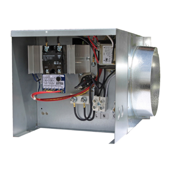
COMPONENT DESCRIPTIONS ACCESSORY RH Series Electric Duct Heaters 2.0 COMPONENT DESCRIPTIONS 2.1 RH-D RH-D heaters use open coil, electric resistance hardware to provide an adjustable heat output. An airflow sensor is provided, checking for minimum airflow. There are two separate thermal cutout devices, the first of which will shut down the heater at 125°F and then automatically... -
Page 11: Rh-W
Output temperature is controlled by an analog 0−10 VAC signal provided by either the wall thermostat supplied with RH-W heaters, a BMS or by a RenewAire Premium Programmable Controller. The heat output of the unit is modulated by means of pulsed current supplied to the heating coils by the SSR, which is controlled by the on-board controller. -
Page 12: Cth291 Thermostat
COMPONENT DESCRIPTION ACCESSORY RH Series Electric Duct Heaters 2.2.1 CTH291 Thermostat (supplied with RH-W heaters) The CTH291 Thermostat is an 0–10 VDC output, dual mode device. It provides an analog 0–10 VDC output signal to the RH-W controller, enabling the controller to modulate the heat output, as needed. -
Page 13: Dimensioned Drawings
DIMENSIONED DRAWINGS RH Series Electric Duct Heaters ACCESSORY 3.0 DIMENSIONED DRAWINGS 3.1 RH-D AND RH-W WITH 6" DUCT COLLAR FIGURE 3.1.0 RH-D AND RH-W 6" DUCT COLLAR DIMENSIONED DRAWING 3.2 RH-D AND RH-W WITH 8" DUCT COLLAR FIGURE 3.2.0 RH-D AND RH-W 8" DUCT COLLAR DIMENSIONED DRAWING... -
Page 14: Rh-D And Rh-W With 10" Duct Collar
DIMENSIONED DRAWINGS ACCESSORY RH Series Electric Duct Heaters 3.3 RH-D AND RH-W WITH 10" DUCT COLLAR FIGURE 3.3.0 RH-D AND RH-W 10" DUCT COLLAR DIMENSIONED DRAWING 3.4 RH-D AND RH-W WITH 12" DUCT COLLAR FIGURE 3.4.0 RH-D 12" DUCT COLLAR DIMENSIONED DRAWING... -
Page 15: Wiring Schematics
ELECTRICAL RH Series Electric Duct Heaters ACCESSORY 4.0 WIRING SCHEMATICS 4.1 RH-D 120 VAC FIGURE 4.1.0 RH-D 120 VAC WIRING SCHEMATIC 4.2 RH-D 208/240 VAC (1, 2, 3, 4, 5, AND 6 KW) FIGURE 4.2.0 RH-D 208/240 VAC WIRING SCHEMATIC (1, 2, 3, 4, 5, 6 KW) -
Page 16: Rh-D 240 Vac (8, 10, And 11.5 Kw)
ELECTRICAL ACCESSORY RH Series Electric Duct Heaters 4.3 RH-D 240 VAC (8, 10, AND 11.5 KW) FIGURE 4.3.0 RH-D 240 VAC WIRING SCHEMATIC (8, 10, 11.5 KW) 4.4 RH-W 120 VAC FIGURE 4.4.0 RH-W 120 VAC WIRING SCHEMATIC 1.800.627.4499... -
Page 17: Rh-W 208/240 Vac (1, 2, 3, 4, 5, And 6 Kw)
ELECTRICAL RH Series Electric Duct Heaters ACCESSORY 4.5 RH-W 208/240 VAC (1, 2, 3, 4, 5, AND 6 KW) FIGURE 4.5.0 RH-W 208/240 VAC WIRING SCHEMATIC (1, 2, 3, 4, 5, 6 KW) 4.6 RH-W 240 VAC (8, 10, AND 11.5 KW) FIGURE 4.6.0 RH-W 240 VAC WIRING SCHEMATIC (8, 10, 11.5 KW) -
Page 18: Unit Weights
INSTALLATION ACCESSORY RH Series Electric Duct Heaters 5.0 UNIT WEIGHTS 5.1 RH-D AND RH-W WITH 6" DUCT All Electric Duct Heaters with 6" diameter duct collars weigh 10 pounds or less. 5.2 RH-D AND RH-W WITH 8" DUCT All Electric Duct Heaters with 8" diameter duct collars weigh 15 pounds or less. -
Page 19: Ductwork Connections
fl ow. INSTALLATION amount of air required (in cubic feet per minute) to operate the unit is given in the CFM RH Series Electric Duct Heaters ACCESSORY table (30 CFM per kilowatt). -
Page 20: Connect Electric Service
INSTALLATION ACCESSORY RH Series Electric Duct Heaters 6.8 CONNECT ELECTRIC SERVICE WARNING ARC FLASH AND ELECTRIC SHOCK HAZARD All models of Electric Heaters as discussed in this manual operate on high voltages that can cause severe electric shock. Some models of Electric Heaters use high voltages that are capable of causing dangerous arc flash. -
Page 21: Figure 6.9.0 Rh-W Thermostat
INSTALLATION RH Series Electric Duct Heaters ACCESSORY CAUTION RISK OF ELECTRIC SHOCK OR EQUIPMENT DAMAGE Whenever electrical wiring is connected, disconnected or changed, the power supply to the electric heater and its controls must be disconnected. Lock and tag the disconnect switch or circuit breaker to prevent accidental reconnection of electric power. -
Page 22: Figure 6.9.1 Thermostat Wiring Illustration
INSTALLATION ACCESSORY RH Series Electric Duct Heaters PROVIDE FIELD WIRING FROM THESE THREE TERMINALS TO TERMINAL LUGS ON RH-W CONTROLLER. SEE WIRING SCHEMATICS 6.4, 6.5 AND 6.6 IN THIS MANUAL. CONNECT OPTIONAL OCCUPANCY SENSOR OR TIMER TO TERMINALS 4 AND 5. -
Page 23: Figure 6.9.3 Comfort Mode Screen Shot
INSTALLATION RH Series Electric Duct Heaters ACCESSORY FOR THERMOSTATS THAT DO NOT HAVE EITHER AN OCCUPANCY SENSOR OR A TIMER: When line voltage is applied to the heater, it automatically provides power to the CTH291 thermostat. The LCD screen on the thermostat will show the current (ambient) temperature and a small indicator symbol at the bottom shows whether or not there is a call for heat. -
Page 24: Low Voltage Wiring Entry Point (Rh-W Only)
INSTALLATION ACCESSORY RH Series Electric Duct Heaters 6.9.1 Low Voltage Wiring Entry Point (RH-W Only) Low voltage wiring is to be brought into the unit through one of the factory-provided knockouts located on the side of the control box. See the dimensioned drawings in Section 3.0 of this manual. -
Page 25: Maintenance
7.1 RH-D ANNUAL MAINTENANCE There is no required annual maintenance for any RH-D heater. 7.2 RH-W ANNUAL MAINTENANCE RH-W heaters have a fault indicator LED. RenewAire suggests that the LED be checked annually for indication of detected problems. 7.3 RH-D TROUBLE SHOOTING 7.3.1 Testing AFS (PN 990804) and DS (PN 990805) Sensors... -
Page 26: Testing Heating Elements
22). Review Dip Switches settings. (Refer to instructions on page 22). Note for Dip switch 2: Reverse acting: 0–VDC = Full OFF/10VDC = Full ON (RenewAire DEFAULT). Direct acting: 0–VDC = Full ON/10VDC = Full OFF Troubleshooting notes: 1. If the display is showing two straight lines, the external sensor is defective or not connected to terminal 7 and 8 (if configured for external sensor - Dip switch 3 = ON). -
Page 27: Testing The S2 Airflow Sensor
MAINTENANCE RH Series Electric Duct Heaters ACCESSORY 7.4.2 Testing the AFS Airflow Sensor (PN 990804) Remove S2 airflow sensor from PSSR board and measure the ohms across the Thermistor: The reading should be 10KΩ at 77°F. If the temperature is higher, the resistance will go down and if the temperature is lower, the resistance will go up. -
Page 28: Sequence Of Operations
MAINTENANCE ACCESSORY RH Series Electric Duct Heaters 7.5 SEQUENCE OF OPERATION 7.5.1 RH-D Heaters The heater operates on either 120 VAC or 240 VAC, 1 phase, 60 Hz. The heater will maintain outlet air temperature set by a potentiometer on the controller whenever there is airflow. -
Page 29: Factory Assistance
TO CONTACT RENEWAIRE CUSTOMER SERVICE: CALL 800-627-4499 RenewAireSupport@RenewAire.com EMAIL: Remember that RenewAire Customer Service can only assist with the products sold by RenewAire and their options, it cannot resolve engineering issues that result from air handling system design by others. 1.800.627.4499... -
Page 30: Service Parts
SERVICE PARTS ACCESSORY RH Series Electric Duct Heaters 9.0 SERVICE PARTS 9.1 RH-D 1, 2, 3, 4, 5, AND 6 KW SERVICE PARTS FIGURE 9.1.0 RH-D 1, 2, 3, 4, 5, AND 6 KW SERVICE PARTS 9.2 RH-D 8, 10, AND 11.5 KW SERVICE PARTS FIGURE 9.2.0 RH-D 8, 10, AND 11.5 KW SERVICE PARTS... -
Page 31: Rh-W 1, 2, 3, 4, 5, And 6 Kw Service Parts
SERVICE PARTS RH Series Electric Duct Heaters ACCESSORY 9.3 RH-W 1, 2, 3, 4, 5, AND 6 KW SERVICE PARTS FIGURE 9.3.0 RH-W 1, 2, 3, 4, 5, AND 6 KW SERVICE PARTS 9.4 RH-W 8, 10, AND 11.5 KW SERVICE PARTS FIGURE 9.4.0 RH-W 8, 10, AND 11.5 KW SERVICE PARTS... - Page 32 About RenewAire For over 30 years, RenewAire has been a pioneer in enhancing indoor air quality (IAQ) in commercial and residential buildings of every size.This is achieved while maximizing sustainability through our fifth-generation, static-plate, enthalpic-core Energy Recovery Ventilators (ERVs) that optimize energy efficiency, lower capital costs via load reduction and decrease operational expenses by minimizing equipment needs, resulting in significant energy savings.
Need help?
Do you have a question about the RH Series and is the answer not in the manual?
Questions and answers