Sign In
Upload
Manuals
Brands
Renesas Manuals
Control Unit
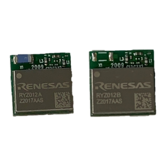
RYZ012
Renesas RYZ012 Manuals
Manuals and User Guides for Renesas RYZ012. We have
1
Renesas RYZ012 manual available for free PDF download: User Manual
Renesas RYZ012 User Manual (206 pages)
Multi-Standard Wireless Communication Module for Bluetooth 5 Low Energy and 802.15.4
Brand:
Renesas
| Category:
Control Unit
| Size: 4 MB
Table of Contents
Table of Contents
4
Contents
4
List of Figures
14
List of Tables
15
Pin Descriptions
17
Figure 1. Pin Assignments - Top View
17
Table 1. Pin Descriptions
17
MCU Description
18
Register Description
18
Table 2. Register File
18
Memory
19
Flash Memory
19
Table 3. Physical Memory Map
19
SRAM Memory
20
Table 4. Flash Memory Partition
20
Table 5. E-Fuse Information
20
Peripheral Registers
21
Figure 2. Reading and Writing Analog Registers
21
Register Reference
22
ARA:ADDR - Analog Register Address
22
ARA:DATA - Analog Register Data
22
ARA:CTRL - Access Control
22
System Control
23
Reset
23
Power Supply
23
Power-On-Reset (POR) and Brown-Out Detect
23
Figure 3. Power Control Logic
23
Figure 4. Power-Up Sequence
24
Figure 5. Power down Sequence
25
Table 6. Characteristics of the Power Control Logic
25
Power Management
26
Active Mode
26
Idle Mode
26
Suspend Mode
26
Deep Sleep Mode
26
Table 7. Power Saving Modes Overview
26
Standby Mode
27
Shutdown Mode
27
Wakeup Sources
27
Retention Registers
27
Figure 6. Wakeup Logic
27
Clock
28
System Clock
28
Figure 7. Clock Tree
28
Peripheral Clocks
29
Register Reference
29
SCTL:PRR - Peripheral Reset Register
29
SCTL:PCEN - Peripheral Clock Enable 1
31
SCTL:HSC1 - System Clock Configuration
33
SCTL:I2SCC - I2S Clock Control
34
SCTL:I2S_MOD - I2S Clock Modifier
34
SCTL:DMICC - DCMI Clock Control
34
SCTL:DMIC_MOD - DCMI Clock Modifier
35
SCTL:WAKEUPEN - Wakeup Enable Digital Module Control
35
SCTL:LPRC - Low-Power and Reset Control
36
SCTL:HSC2 - HS1 Clock Configuration
36
SCTL:WDSTATE - Watchdog Status
37
SCTL:LSC - Oscillator Clock Configuration
37
Analog Register Reference
38
SCTL:PDC0 - Power down Control
38
SCTL:PDC1 - Power down Control
39
SCTL:PON_DLY - Power on Delay
39
SCTL:WKUPEN - Wakeup Enable Module Control
40
SCTL:RD0 - Retention Data 0
40
SCTL:RD1 - Retention Data 1
40
SCTL:RD2 - Retention Data 2
41
SCTL:RD3 - Retention Data 3
41
SCTL:RD4 - Retention Data 4
41
SCTL:RD5 - Retention Data 5
41
SCTL:RD6 - Retention Data 6
42
SCTL:RD7 - Retention Data 7
42
SCTL:SSTATUS - System Status
42
SCTL:APCTRL - Analog Power Control
43
Interrupt System
44
Table 8. List of Interrupts
44
Register Reference
45
IRQ:MASK - Interrupt Mask Configuration
45
IRQ:GIEN - Global Interrupt Enable
46
IRQ:PRIO - Interrupt Priority Configuration
47
IRQ:IPS - Interrupt Pending Status
48
General Purpose IO
50
Figure 8. Schematic of a GPIO Bit
50
Table 9. GPIO Configuration Register Overview
50
GPIO to Timer and Interrupt Mapping
51
GPIO / Peripheral Multiplexing
51
Figure 9. GPIO Signal Forwarding to Timers and Interrupt System
51
Table 10 Peripheral Function Mapping
52
GPIOA Register Reference
53
GPIOA:ID - GPIOA Input Data
53
GPIOA:IEN - GPIOA Input Enable
53
GPIOA:ODIS - GPIOA Output Disable
54
GPIOA:OD - GPIOA Output Data
54
GPIOA:INTPOL - GPIOA Interrupt Polarity
54
GPIOA:DS - GPIOA Driving Strength
55
GPIOA:MODE - GPIOA Mode Selection
55
GPIOA:INTEN - GPIOA Interrupt Enable
55
GPIOA:PFS - Peripheral Function Selection Register
56
GPIOA:T0G2R - GPIOA Extra Peripheral Mapping 0
56
GPIOA:T1G2R - GPIOA Extra Peripheral Mapping 1
57
GPIOA:T2 - GPIOA Extra Peripheral Mapping 2
57
GPIOA Analog Register Reference
58
GPIOA:PRC - Port a Pull Register Control Low
58
GPIOA:WKUPPOL - GPIOA Wakeup Polarity Control
58
GPIOA:WKUPEN - GPIOA Wakeup Enable
58
GPIOB Register Reference
59
GPIOB:ID - GPIOB Input Data
59
GPIOB:IEN - GPIOB Input Enable
59
GPIOB:ODIS - GPIOB Output Disable
60
GPIOB:OD - GPIOB Output Data
60
GPIOB:INTPOL - GPIOB Interrupt Polarity
60
GPIOB:DS - GPIOB Driving Strength
61
GPIOB:MODE - GPIOB Mode Selection
61
GPIOB:INTEN - GPIO Interrupt Enable PB
61
GPIOB:PFS - Peripheral Function Selection Register
62
GPIOB:T0G2R - GPIOB Extra Peripheral Mapping 0
63
GPIOB:T1G2R - GPIOB Extra Peripheral Mapping 1
63
GPIOB:T2 - GPIOB Extra Peripheral Mapping 2
63
GPIOB Analog Register Reference
64
GPIOB:PRC - Port B Pull Resistor Control Low
64
GPIOB:WKUPPOL - GPIOB Wakeup Polarity Control
64
GPIOB:WKUPEN - GPIOB Wakeup Enable
64
GPIOC Register Reference
65
GPIOC:ID - GPIOC Input Data
65
GPIOC:IEN - GPIOC Input Enable
65
GPIOC:ODIS - GPIOC Output Disable
66
GPIOC:OD - GPIOC Output Data
66
GPIOC:INTPOL - GPIOC Interrupt Polarity
66
GPIOC:DS - GPIOC Driving Strength
67
GPIOC:MODE - GPIOC Mode Selection
67
GPIOC:INTEN - GPIOC Interrupt Enable PC
67
GPIOC:PFS - Peripheral Function Selection Register
68
GPIOC:T0G2R - GPIOC Extra Peripheral Mapping 0
69
GPIOC:T1G2R - GPIOC Extra Peripheral Mapping 1
69
GPIOC:T2 - GPIOC Extra Peripheral Mapping 2
69
GPIOC Analog Register Reference
70
GPIOC:PRC - Port C Pull Resistor Control Low
70
GPIOC:WKUPPOL - GPIOC Wakeup Polarity Control
70
GPIOC:WKUPEN - GPIOC Wakeup Enable
70
GPIOD Register Reference
71
GPIOD:ID - GPIOD Input Data
71
GPIOD:IEN - GPIOD Input Enable
71
GPIOD:ODIS - GPIOD Output Disable
72
GPIOD:OD - GPIOD Output Data
72
GPIOD:INTPOL - GPIOD Interrupt Polarity
72
GPIOD:DS - GPIOD Driving Strength
73
GPIOD:MODE - GPIOD Mode Selection
73
GPIOD:INTEN - GPIOD Interrupt Enable
73
GPIOD:PFS - Peripheral Function Selection Register
74
GPIOD:T0G2R - GPIOD Extra Peripheral Mapping 0
74
GPIOD:T1G2R - GPIOD Extra Peripheral Mapping 1
75
GPIOD:T2 - GPIOD Extra Peripheral Mapping 2
75
GPIOD Analog Register Reference
76
GPIOD:PRC - Port D Pull Register Control Low
76
GPIOD:WKUPPOL - GPIOD Wakeup Polarity Control
76
GPIOD:WKUPEN - GPIOD Wakeup Enable
76
I2C Interface
77
Communication Protocol
77
I2C Slave Mode
77
DMA Mode
77
Figure 10. I2C Timing Chart
77
Mapping Mode
78
Figure 11. I2C DMA Mode Read Sequence
78
Figure 12. I2C DMA Mode Write Sequence
78
Figure 13. I2C Mapping Mode Read Sequence
78
Figure 14. I2C Mapping Mode Write Sequence
78
Master Mode
79
Write Transfer
79
Read Transfer
79
Notes on Concurrent I2C and SPI Usage
79
Register Reference
80
I2C:CPRE - I2C Clock Prescaler Configuration
80
I2C:SADR - I2C Slave Address Configuration
80
I2C:MST - I2C Master Status
80
I2C:CTRL - I2C General Control
81
I2C:W1D - I2C Master Mode Write Buffer
81
I2C:W2D - I2C Master Mode Write Buffer
82
I2C:W3RD - I2C Master Mode Write/Read Buffer
82
I2C:CYCTRL - I2C Cycle Control
82
I2C:LHADR - I2C Last Hold Address
83
I2C:MMADR - I2C Mapping Mode Buffer Address
83
I2C:HSTATE - I2C Host Status
84
SPI Interface
85
SPI Master Mode
85
Figure 15. SPI Timing Diagram
85
SPI Slave Mode
86
Register Reference
86
SPI:DATA - SPI Data
86
SPI:CTRL - SPI Control
86
Figure 16. SPI Slave Mode Read and Write Transfers
86
SPI:MODE - SPI Mode Configuration
87
UART Interface
89
Figure 17. UART Communication
89
Register Reference
90
UART:DATA - UART Data Buffer
90
UART:CLKDIV - UART Clock Divider Configuration
90
UART:CTRL - UART Control
91
UART:RXTIMEOUT - UART RX Timeout Configuration
93
UART:BUFCNT - UART Buffer Count
93
UART:STATUS - UART Status
94
UART:TXRX_STATUS - UART RX/TX Status
94
UART:STATE - UART State
95
Single Wire Interface
95
Timers
95
General-Purpose Timers Timer 0 - Timer 2
95
Mode 0 (System Clock Mode)
95
Mode 1 (GPIO Trigger Mode)
96
Mode 2 (GPIO Pulse Width Mode)
96
Mode 3 (Tick Mode)
96
Watchdog
97
Ltimer
97
Register Reference
98
TIMER:CTRL - Timer Control
98
TIMER:STATUS - Timer Status
99
TIMER:CAPT0 - Timer 0 Capture
100
TIMER:CAPT1 - Timer 1 Capture
100
TIMER:CAPT2 - Timer 2 Capture
101
TIMER:TICK0 - Timer 0 Tick Counter
101
TIMER:TICK1 - Timer 1 Tick Counter
102
TIMER:TICK2 - Timer 2 Tick Counter
102
System Timer
102
Register Reference
103
SYSTIM:CNT - System Timer Counter Value
103
SYSTIM:CTRL - System Timer Control
103
Pwm
104
PWM Modes
104
Continuous Mode
104
Figure 18. PWM, PWM Output Generation
104
Counting Mode
105
IR Mode
105
Figure 19. Counting Mode
105
Figure 20. IR Mode
105
Register Reference
106
PWM:EN - PWM Enable
106
PWM:CLKDIV - PWM Clock Divider Configuration
107
PWM:MODE - PWM Mode
107
PWM:DPOL - Pwmx Pin Output Inversion
107
PWM:IPOL - Pwmx_N Pin Output Inversion
108
PWM:POL - PWM Polarity
108
PWM:TCMP0 - PWM0 Capture Mode Time
108
PWM:TMAX0 - PWM0 Maximum Cycle Time
109
PWM:TCMP1 - PWM1 Capture Mode Time
109
PWM:TMAX1 - PWM1 Maximum Cycle Time
109
PWM:TCMP2 - PWM2 Capture Mode Time
110
PWM:TMAX2 - PWM2 Maximum Cycle Time
110
PWM:TCMP3 - PWM3 Capture Mode Time
110
PWM:TMAX3 - PWM3 Maximum Cycle Time
111
PWM:TCMP4 - PWM4 Capture Mode Time
111
PWM:TMAX4 - PWM4 Maximum Cycle Time
111
PWM:TCMP5 - PWM5 Capture Mode Time
112
PWM:TMAX5 - PWM5 Maximum Cycle Time
112
PWM:PNUM0 - PWM0 Pulse Number
112
PWM:MASK0 - PWM Interrupt Mask
113
PWM:INT0 - PWM Interrupt Status
114
PWM:MASK1 - PWM Interrupt Mask
115
PWM:INT1 - PWM Interrupt Status
115
PWM:CNT0 - PWM0 Counter Value
116
PWM:CNT1 - PWM1 Counter Value
116
PWM:CNT2 - PWM2 Counter Value
116
PWM:CNT3 - PWM3 Counter Value
117
PWM:CNT4 - PWM4 Counter Value
117
PWM:CNT5 - PWM5 Counter Value
117
PWM:NCNT0 - PWM0 Pulse Count Value
118
PWM:TCMP0_SHADOW - PWM0 Shadow Capture Mode Time
118
PWM:TMAX0_SHADOW - PWM0 Maximum Shadow Cycle Time
118
PWM:FIFO_DAT_ENTRY - FIFO Data Entry
119
PWM:FIFO_NUM_LVL - FIFO Interrupt Trigger Entry
119
PWM:FIFO_SR - PWM FIFO Status
119
PWM:FIFO_CLR - PWM FIFO Clear
120
Audio
121
Audio Input Path
121
AMIC Input
121
DMIC Input
121
Figure 21. Audio Input Path
121
Table 11. Audio Data Flow Direction
121
I2S Input
122
Dfifo
122
Audio Input Processing
122
Figure 22. Audio Input Processing
122
Decimation Filter
123
Low Pass Filter (LPF)
123
Down-Sampling
123
High Pass Filter (HPF)
123
Adaptive Level Control (ALC)
123
Audio Input Path Register Reference
125
AUDIO_IN:DFIFO0_BADR0 - DFIFO0 Base Address
125
AUDIO_IN:DFIFO0_BADR1 - DFIFO0 Base Address
125
AUDIO_IN:DFIFO0_DEPTH - DFIFO0 Depth
125
AUDIO_IN:DFIFO0_BADR2 - DFIFO0 Base Address
125
AUDIO_IN:DFIFO1_BADR0 - DFIFO1 Base Address
126
AUDIO_IN:DFIFO1_BADR1 - DFIFO1 Base Address
126
AUDIO_IN:DFIFO1_DEPTH - DFIFO1 Depth
126
AUDIO_IN:DFIFO1_BADR2 - DFIFO1 Base Address
126
AUDIO_IN:DFIFO2_BADR0 - DFIFO2 Base Address
127
AUDIO_IN:DFIFO2_BADR1 - DFIFO2 Base Address
127
AUDIO_IN:DFIFO2_DEPTH - DFIFO2 Depth
127
AUDIO_IN:DFIFO2_BADR2 - DFIFO2 Base Address
127
AUDIO_IN:DFIFO0_LLEV - DFIFO0 Interrupt Level
128
AUDIO_IN:DFIFO0_HLEV - DFIFO0 Interrupt Level
128
AUDIO_IN:DFIFO1_HLEV - DFIFO1 Interrupt Level
128
AUDIO_IN:DFIFO2_HLEV - DFIFO2 Interrupt Level
128
AUDIO_IN:DFIFOMODE - DFIFO Mode
129
AUDIO_IN:DFIFOAIN - DFIFO Analog Input Configuration
130
AUDIO_IN:DFIFODEC - DFIFO QDEC Configuration
131
AUDIO_IN:DFIFOIRQST - Dfifox Interrupt Status
131
AUDIO_IN:DFIFO0_RPTR - Read FIFO0 PTR
132
AUDIO_IN:DFIFO0_WPTR - Write FIFO0 PTR
132
AUDIO_IN:DFIFO1_RPTR - Read FIFO1 PTR
133
AUDIO_IN:DFIFO1_WPTR - Write FIFO1 PTR
133
AUDIO_IN:DFIFO2_RPTR - Read FIFO2
133
AUDIO_IN:DFIFO2_WPTR - Write FIFO2 PTR
134
AUDIO_IN:DFIFO0_NUM - Number FIFO0
134
AUDIO_IN:DFIFO1_NUM - Number FIFO1
134
AUDIO_IN:DFIFO2_NUM - Number FIFO2
135
AUDIO_IN:DFIFO_MANUAL - DFIFO Manual Mode
135
AUDIO_IN:DFIFO_MAN_DAT0 - DFIFO Manual Mode Data
135
AUDIO_IN:DFIFO_MAN_DAT1 - DFIFO Manual Mode Data
136
AUDIO_IN:DFIFO_MAN_DAT2 - DFIFO Manual Mode Data
136
AUDIO_IN:DFIFO_MAN_DAT3 - DFIFO Manual Mode Data
136
AUDIO_IN:AUDIO_CFG - Audio Configuration
137
AUDIO_IN:ADC_MUL - ADC Calibration Multiplicator
137
AUDIO_IN:ADC_BIAS - ADC Calibration Bias
138
AUDIO_IN:ALC_FLT_CTRL - ALC Filter Control
138
AUDIO_IN:ALC_VOL_L - ALC Left Channel Setting
139
AUDIO_IN:ALC_VOL_R - ALC Right Channel Setting
139
AUDIO_IN:ALC_VOL_H - Maximum PGA Gain Limit
139
AUDIO_IN:ALC_VOL_THH - PGA High Volume Target
140
AUDIO_IN:ALC_VOL_THL - PGA LOW Volume Target
140
AUDIO_IN:ALC_VOL_THN - PGA Noise Level Target
140
AUDIO_IN:ALC_VOL_L_R - PGA Left Channel Gain
141
AUDIO_IN:ALC_VOL_R_R - PGA Right Channel Gain
141
AUDIO_IN:ALC_PEAK_TICK_L - Peak Tick
141
AUDIO_IN:ALC_PEAK_TICK_H - Peak Tick
141
AUDIO_IN:ALC_CFG - ALC Configuration
142
AUDIO_IN:ALC_COEF_IIR - IIR Coefficient
142
AUDIO_IN:ALC_DAT_MASK - Data Mask
143
AUDIO_IN:ALC_INC_SPD - PGA Gain Increase Speed
143
AUDIO_IN:ALC_INC_MAX - PGA Maximum Gain Increase
143
AUDIO_IN:ALC_DEC_SPD - PGA Gain Decrease Speed
143
AUDIO_IN:ALC_DEC_MAX - PGA Maximum Gain Decrease
144
AUDIO_IN:ALC_NOI_SPD - PGA Gain Decrease Speed (Noise)
144
AUDIO_IN:ALC_NOI_MAX - PGA Maximum Gain Decrease (Noise)
144
AUDIO_IN:CUR_PGA_GAIN_L - PGA Left Channel Current Gain
144
AUDIO_IN:CUR_PGA_GAIN_R - PGA Right Channel Current Gain
145
AUDIO_IN:PGA_MAN_SPD - PGA Gain Manual Increase Speed
145
AUDIO_IN:PGA_MAN_TARGET_L - PGA Left Channel Manual Target
145
AUDIO_IN:PGA_VALUE_L - PGA Left Channel Value
146
AUDIO_IN:PGA_FIX_VALUE - PGA Fixed Value
146
AUDIO_IN:PGA_R_L - Change PGA Channel Control
146
AUDIO_IN:PGA_MAN_TARGET_R - PGA Right Channel Manual Target
147
AUDIO_IN:PGA_VALUE_R - PGA Right Channel Value
147
Audio Output Path
147
Figure 23. Audio Output Path
147
Rate Matching
148
Sigma Delta Modulator (SDM)
148
Figure 24. Linear Interpolation
148
Figure 25. Delay Interpolation
148
Register Configuration
149
Figure 26. SDM Block Diagram
149
Audio Output Path Register Reference
150
AUDIO_OUT:CTRL - Audio out Control
150
AUDIO_OUT:MIDGRP - Middle of GRP
151
AUDIO_OUT:VOL_CTRL - Audio out Volume Control
151
AUDIO_OUT:PWM_CTRL - Audio out PWM Control
151
AUDIO_OUT:ASCL_TUNE - Tune Step
152
AUDIO_OUT:I2SCLK - I2S Clock Configuration
152
AUDIO_OUT:ASCL_STEP - Rate Matching Block Step
153
AUDIO_OUT:PN_CTRL - PN Generator Control
153
AUDIO_OUT:CONST_LEFT - Constant Left Channel
154
AUDIO_OUT:CONST_RIGHT - Constant Right Channel
155
Quadrature Decoder
156
Input Pin Selection
156
Common Mode and Double Accuracy Mode
156
Figure 27. Common Mode
156
Table 12. Input Pin Selection
156
Read Real-Time Counting Value
157
QDEC Reset
157
Other Configuration
157
Figure 28. Double Accuracy Mode
157
Figure 29. Read Real-Time Counting Value
157
Timing
158
Figure 30. Shuttle Mode
158
Figure 31. Timing Sequence
158
Table 13. Timing Constraints
158
Register Reference
159
QDEC:COUNT - QDEC Pulse Edge Count
159
QDEC:GC - QDEC General Configuration
159
QDEC:CHA - QDEC Input Channel a
160
QDEC:CHB - QDEC Input Channel B
160
QDEC:RST - QDEC Reset Control
161
QDEC:DOUBLE - QDEC Mode Configuration
161
QDEC:DATA_LOAD - QDEC Data Status
161
Sar-Adc
162
ADC Control
162
ADC Channel Selection
162
ADC Set State
162
Figure 32. Conversion Sequence for All Channels
162
ADC Capture State
163
Use Cases
163
Table 14. Configuration Setting for Different ADC Use Cases
163
Table 15. Register Setting for L/R/M Channel
164
Analog Register Reference
165
SAR_ADC:VREF_CTRL - SAR Reference Voltage Configuration
165
SAR_ADC:CHM_INPUT - SAR Input Misc Channel Configuration
166
SAR_ADC:CHL_INPUT - SAR Input Left Channel Configuration
168
SAR_ADC:CHR_INPUT - SAR Input Right Channel Configuration
170
SAR_ADC:CHCFG - SAR General Channel Configuration
171
SAR_ADC:TSAMP - SAR Sampling Time Configuration
173
SAR_ADC:CAPCFG - SAR Channel Capture Configuration
174
SAR_ADC:CHEN - SAR Channel Enable Control
174
SAR_ADC:CLKDIV - SAR Clock Divider Configuration
175
SAR_ADC:DATM - SAR Data Misc Channel
175
SAR_ADC:APSC - Analog Pre-Scaler
175
Programmable Gain Amplifier
176
Power-On / down
176
Input Channel
176
Figure 33. Block Diagram of PGA
176
Adjust Gain
177
Analog Register Reference
177
PGA:VINSEL - PGA Channel Input Configuration
177
Temperature Sensor
179
Figure 34. Block Diagram of Temperature Sensor
179
Low Power Comparator
180
Power-On/Down
180
Input Channel Selection
180
Figure 35. Block Diagram of Low Power Comparator
180
Mode and Reference Selection
181
Select Scaling Coefficient
181
Low Power Comparator Output
181
Analog Register Reference
181
LPC:CFG0 - LPC Configuration
181
LPC:CFG1 - LPC Configuration
182
LPC:RDY - LPC Status
182
Aes
183
RISC Mode
183
DMA Mode
183
Aes-CCM
183
Register Reference
184
AES:CTRL - AES Control
184
AES:DAT - AES Data
184
AES:KEY - AES Key Data
184
Bluetooth Low Energy/802.15.4/2.4Ghz RF Transceiver
187
Block Diagram
187
Baseband
187
Figure 36. Block Diagram of RF Transceiver
187
Packet Format
188
RSSI and Frequency Offset
188
Table 16. Packet Format in Standard 1Mbps Bluetooth Low Energy Mode
188
Table 17. Packet Format in Standard 2Mbps Bluetooth Low Energy Mode
188
Table 18. Packet Format in Standard 500Kbps/125Kbps Bluetooth Low Energy Mode
188
Table 19. Packet Format in 802.15.4 Mode
188
Table 20. Packet Format in Proprietary Mode
188
Electrical Characteristics
189
Absolute Maximum Ratings
189
Recommended Operating Conditions
189
Table 21. Absolute Maximum Ratings
189
Table 22. Recommended Operating Conditions
189
Electrical Characteristics
190
Table 23. Electrical Characteristics
190
Table 24. AC Characteristics
190
Table 25. Bluetooth Low Energy, 1 Mbps Mode
191
Table 26. Bluetooth Low Energy, 2 Mbps Mode
191
Table 27. Bluetooth Low Energy, 500 Kbps Mode
192
Table 28. Bluetooth Low Energy, 125 Kbps Mode
193
Table 29. IEEE 802.15.4, 250Kbps
194
SPI Characteristics
195
Table 30. SPI Characteristics (over Process, Voltage 1.9-3.6V, and T a = -40 to +85°C)
195
I2C Characteristics
196
Flash Characteristics
196
Table 31. I2C Characteristics (over Process, Voltage 1.9-3.6V, and T a = -40 to +85°C)
196
Table 32. Flash Characteristics (T a = -40 to +85°C)
196
Package Outline Drawings
197
Table 33. Module Dimensions
204
Soldering Information
205
Figure 37. Recommended Soldering Profile
205
Ordering Information
206
Marking Diagram
206
Revision History
206
Advertisement
Advertisement
Related Products
Renesas RYZ014
Renesas RY9012A0
Renesas RY7011
Renesas R8C FAMILY
Renesas R8C/2x SERIES
Renesas RX110
Renesas RX111
Renesas RX230
Renesas RX631
Renesas RX63N
Renesas Categories
Computer Hardware
Motherboard
Microcontrollers
Adapter
Switch
More Renesas Manuals
Login
Sign In
OR
Sign in with Facebook
Sign in with Google
Upload manual
Upload from disk
Upload from URL