Sign In
Upload
Manuals
Brands
RC Factory Manuals
Toy
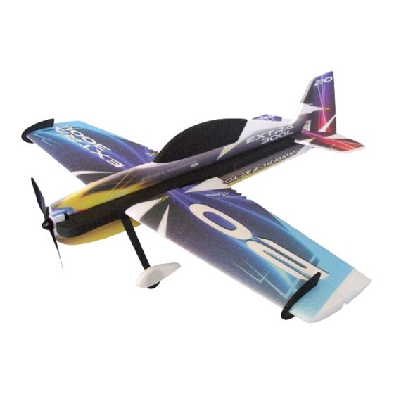
EXTRA 300L
RC Factory EXTRA 300L Plane Manuals
Manuals and User Guides for RC Factory EXTRA 300L Plane. We have
1
RC Factory EXTRA 300L Plane manual available for free PDF download: Service Manual
RC Factory EXTRA 300L Service Manual (491 pages)
Brand:
RC Factory
| Category:
Toy
| Size: 13 MB
Table of Contents
Chapter 05 Time Limits/Maintenance Checks
39
Table of Contents
39
Time Limit Components
41
Overhaul Schedule
41
Recommended Replacement Times
42
Time between Inspection
43
Scheduled Maintenance Checks
44
General
44
25 Hour Inspection - Engine
44
25 Hour Inspection - Aircraft
44
Unscheduled Maintenance Checks
74
Violent Stopping of the Engine (Propeller Strike)
74
Hard Landing
74
Engine Fire
76
Lightning Strike
76
Flightline Inspections
77
Chapter 06
79
General
80
Main Data
81
Main Dimensions
81
Wing
81
Elevator
82
Horizontal Tail
82
Rudder
82
Vertical Tail
82
Chapter 07
85
Balance Weight
86
Jacking
86
Hoisting Points
87
Shoring
87
Shoring the Front
87
Shoring the Front
88
Shoring the Tail
88
Chapter 10
102
General
103
Parking / Storage
104
Mooring
105
Return to Service
106
Chapter 12
108
General
109
Refueling
110
Replenishing
110
Defueling
112
Fuel Drains
112
Replenishment of Engine Oil
112
Oil Change
116
Replenishment of Brake Fluid
117
Tire Inflation
119
Exterior Cleaning
120
Scheduled Servicing
120
Engine Cleaning
121
Interior Cleaning
121
Removal of Snow and Ice
123
Unscheduled Servicing
123
Chapter 20 Standard Practices - Airframe
125
General
126
Standard Practices Airframe
127
Type of Bolts
127
Width Across Flats for Metric Bolts
129
Torque Values
130
Special Torque Values
131
Coin Tapping
132
Measuring Techniques
132
Flexible Hose
133
Connection Types PA Hoses
136
Fittings
138
Control Cables
139
Control Cables
142
Assembly Instruction
144
Assembly Instruction after Container Shipping
144
General
144
Chapter 23
148
Becker AR 3201
149
Becker AR 3201 Front View
150
General
149
Speech Communication
149
Circuit Breaker
151
VHF Whip Antenna (Moba 210 FA) Becker 1A001
151
Whip Antenna
151
Interphone (Intercom)
153
Intercom-Connectors
153
Chapter 24 Electrical Power
155
General
156
DC-Generation
157
Battery
158
Alternator
159
Master Relay
159
Alternator and Accessories
160
Drive Belt
162
Alternator Pulley
164
Circuit Breaker
165
DC Electrical Load Distribution
165
Lever Switch
166
Subminiature Pushbotton Switch
166
Relay
167
Chapter 25 Equipment and Furnishings
169
Flight Compartments
170
Front Seat
170
Rear Seat
170
Seat Belts
171
Strap Assembly
172
Shoulder Strap Attachment
173
Aircraft Document Bag
174
Chapter 27
176
Figure 1
177
Controls
177
Figure 2
178
Spacer Sleeve Displaced
178
Control Surface Mounting Aid
178
Figure 4
179
Control Surface Deflections
179
General
177
Control Rods
180
Figure 5
181
Control Rod Measurement
181
Control Rod Identification
181
Table 1
181
Control Rod Measurement & Rod End Alignment
181
Figure 7
182
Control Rod Check Hole
182
Bellcranks
183
Figure 8
183
Control Levers and Rods Removal/Installation
183
Figure 9
184
Front Control Stick Removal/Installation
184
Front Control Stick
184
Rear Control Stick
185
Torque Tube
185
Aileron Control
186
Figure 10
187
Aileron Control
187
Ailerons
188
Figure 11
188
Neutral Position of Rear Control Stick
188
Figure 12
189
Trailing Edge Alignment
189
Figure 13
190
Spade Rigging
190
Spades
190
Rudder Control
191
Figure 14
192
Rudder Control
192
Rudder
193
Bottom Hinge Bellcranks
194
Bottom Hinge Bracket
194
Control Cable
194
Figure 15
195
Rear Pedal Template
195
Figure 16
197
Front Pedal Template
197
Fairlead
198
Elevator Control
199
Figure 17
200
Elevator and Trim Tab Control
200
Elevator
201
Neutral Position of the Rear Control Stick
202
Lath on Chord Line
202
Figure 20
203
Trim Tab Rigging
203
Trim Tab
203
Chapter 28 Fuel
206
General
208
Fuel System (Configuration 1)
210
Fuel System (Configuration 2)
211
Storage
212
Acro Tank
213
Center Tank
213
Acro Tank Flop Tube
214
Flop Tube Removal/Installation
214
Storage (Configuration 1)
215
Storage (Configuration 2)
216
Wing Tank Inspection Door
217
Inspection Door Removal/Installation
217
Wing Tank Outlets
218
Wing Tank Outlets Removal/Installation
218
Center Tank Filler Neck
219
Wing Tank Filler Neck
219
Filler Neck Sealing Lip
220
Filler Neck and Sealing Lip Removal/Installation
220
Ventilation Line
221
Distribution (Configuration 1)
222
Distribution (Configuration 2)
224
Fuel Selector Valve and Control Rod
225
Fuel Selector Valve and Control Rod (up to SN 78)
226
Fuel Selector Valve and Control Rod (from SN 79)
227
Gascolator
228
Gascolator Removal/Installation
228
Electrical Boost Pump
229
Boost Pump Removal/Installation
229
Fuel Line
230
Indicating (Configuration 1)
231
Indicating (Configuration 2)
233
Fuel Quantity Indicator
234
Fuel Quantity Indicator (Center Tank)
235
Tubular Tank Unit (Center Tank)
235
Lever-Type Tank Unit (Wing Tank)
236
Chapter 31 Indication \ Recording System
240
General
241
Instrument and Control Panels
242
Rear Instrument Panel
242
Front Instrument Panel
244
Front Instrument Panel Removal/Installation
245
Rear Instrument Cover
246
Instrument Cover Removal/Installation
246
Typical Instruments
247
Typical Instrument Attachments
247
Central Warning Systems
248
Stall Warning System
248
Chapter 32 Landing Gear
250
Landing Gear
251
Wheel Rake and Toe-In
251
Main Landing Gear
252
Top Half of the Mounting Clamp
252
Main Landing Gear Mounting
253
Tail Spring
253
Wheel Axis
253
Tail Wheel Fork Assembly
254
Tail Wheel, Fork and Spring
255
Wheels and Brakes
256
Brake System
258
Master Cylinder
259
Master Cylinder Mounting Aid
259
Wheel Fairing
260
Tail Wheel
262
Chapter 33 Lights
264
Flight Compartment
265
Low Voltage Monitor
265
Exterior
267
Navigation/Strobe Light
267
Navigation/Strobe Light System
267
Navigation/Strobe Lights Removal/Installation
268
Landing Light System
269
Strobe Light Power Supply
269
Head Lamp
270
Landing Light
270
Landing Light
271
Chapter 34
273
General
274
Flight Environment Data
275
Pitot/Static Drain
275
Pitot/Static System
275
Pitot Tube
276
Pitot Tube Attachment Block
276
Altimeter
277
Airspeed Indicator
278
Attitude and Direction
279
Magnetic Compass
279
Turn and Bank Indicator
280
Dependent Position Determining
281
Transponder
281
Chapter 51 Standard Practices and Structures - General
283
Access Panel Identification
284
General
284
Figure 1
285
Access Panel Identification
285
Damage Classification
287
Investigation
287
Repair Criteria and Limits
288
Composite Parts
289
Materials
289
Metal Components
292
Aluminium Components
294
Control Surface Balancing
296
Figure 2
296
Balancing Mandrels
296
Figure 3
298
Determination of Control Surface Moments
298
Weighing and Determination of Control Surface Moments
296
Repair of Reinforced Glass and Carbon Fibre Components
300
Repairs
300
Figure 5
302
Minor Surface Damage
302
Figure 6
304
Curing Cycle Resin L20/SL
304
Level Sanding of Surrounding Area
304
Damage of Complete Sandwich
304
Repair of Sandwich Material
302
Repair of Laminates
307
Figure 9
309
Repair of Spars
311
Structural Repair of Steel Components
312
Painting of Composite Parts
313
Aluminium and Steel Components Refinishing
314
Figure 10
317
Empennage Attachment Bushings
317
Figure 11
320
Wing Main Spar Attachment Flange Bushings
320
Re-Bonding of Bushings
317
Chapter 55
342
General
343
Horizontal Stabilizer
344
Elevator
347
Vertical Stabilizer
348
Rudder
351
Chapter 57
353
General
354
Layer Sequence Wing
355
Layer Sequence Wing
357
Wing
358
Wing Tip
362
Ailerons
363
Chapter 71 Power Plant
375
Cowling
376
Engine Mount
378
Shock Mounts
380
Air Baffles
382
Chapter 73 Engine Fuel and Control
394
Controlling
395
Throttle
395
Throttle Control
395
Throttle Control Cable
396
Firesleeve Length
397
Rear Throttle Control Lever
398
Throttle Control Levers
398
Throttle Control Cable Rigging
399
Front Throttle Control Lever
400
Mixture
401
Mixture Control
401
Mixture Vernier Control Cable
402
Clamp Sheet to Clamp Block Distance
403
Over-Travel at Mixture Control Unit
404
Mixture Vernier Control Cable Rigging
405
Fuel Pressure
406
Fuel Pressure Wet Line up to SN 1302
406
Fuel Pressure Wet Line from SN 1303
407
Fuel Pressure Gauge
408
Indicating
406
Engine Fitting
408
Sense Line
408
Chapter 77 Engine Indicating
410
General
411
Engine Sensor Locations
411
Power
413
Rpm
413
RPM Sensor
413
Tachometer
413
Manifold Pressure (MAP)
414
Sintered Bronze Filter Location
414
Manifold Pressure Gauge
414
Sense Line
414
Cylinder Head Temperature (CHT)
415
Cylinder Head Temperature Gauge
415
Temperature
415
EGT Sensor
416
Exhaust Gas Temperature (EGT)
416
Exhaust Gas Temperature Gauge
416
Chapter 78 Exhaust
418
General
419
Exhaust System
421
Exhaust Pipe
422
Gasket
422
Muffler
422
Heat Shield
423
Heat Shield Replacement
423
Chapter 79
425
Christen Inverted Oil System
426
General
426
Inverted Oil System, Normal Flight
427
Inverted Oil System, Inverted Flight
428
Valve Balls
429
Distribution
430
Fittings
430
Flexible Hoses
430
Single Oil Cooler System
431
Dual Oil Cooler System
432
Indicating
433
Oil Pressure
433
Oil Pressure Sensor & Wet Line from SN 1303
434
Oil Pressure Sensor & Wet Line up to SN 1302
434
Engine Fitting
435
Oil Pressure Gauge
435
Oil Pressure Wet Line
435
Oil Temperature
436
Oil Temperature Gauge
436
Oil Temperature Sensor
437
Oil Temperature Sensor Location
437
Advertisement
Advertisement
Related Products
RC Factory Extra Slick
RC Factory Extra 330
RC Factory 4682
RC Factory Backyard Series
RC Factory Clik 21
RC Factory Clik 4 NG
RC Factory Crack Laser Pro
RC Factory Crack Pitts Backyard
RC Factory Crack Turbo Beaver
RC Factory Categories
Toy
Drones
More RC Factory Manuals
Login
Sign In
OR
Sign in with Facebook
Sign in with Google
Upload manual
Upload from disk
Upload from URL