Sign In
Upload
Manuals
Brands
Rabe Manuals
Farm Equipment
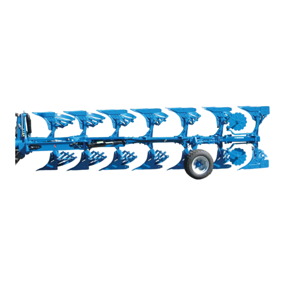
Pavo V 140
Rabe Pavo V 140 Manuals
Manuals and User Guides for Rabe Pavo V 140. We have
1
Rabe Pavo V 140 manual available for free PDF download: Operating Instructions Manual
Rabe Pavo V 140 Operating Instructions Manual (102 pages)
with PAVOtronic
Brand:
Rabe
| Category:
Farm Equipment
| Size: 13 MB
Table of Contents
Introduction
3
Table of Contents
5
1 For Your Safety
9
Explanations about These Operating Instructions
9
Symbol Descriptions
9
Target Audience of These Operating Instructions
9
General Safety Information
10
Intended Use
10
Who May Operate the Implement
10
Operator's Position
11
Safety Instructions - General Usage
11
Safety Instructions - Loading
12
Safety Instructions - Coupling and Uncoupling
13
Safety Instructions - Hydraulics
13
Ballast Calculation
14
Safety Instructions - Travelling by Road / Transport
14
Safety Instructions - Field Use
14
Safety Instructions - Care, Maintenance and Repair
15
Meaning of the Safety Symbols on the Implement
17
2 Scope of Delivery
19
Basic Equipment
19
Additional Equipment
19
3 Description of the Implement
20
Functional Description
20
Description of the Assemblies
21
Tower
21
Rotation Cylinder
21
Transport Lock
22
Parallelogram Cylinder
22
Working Width Cylinder
22
Plough Bodies
22
Combination Wheel
23
Disc Coulter [Additional Equipment]
23
Pick-Up Arm [Additional Equipment]
23
Pavotronic" Electronic Control
24
General Information
24
Layout of Control Unit
24
Technical Data
25
Dimensions and Weight in Basic Configuration
25
Weight of Additional Equipment
26
Required Hydraulic Connections
26
Required Power Connections
26
The Type Plate and Its Position
27
4 Loading
27
5 Preparations
28
Checking Requirements for the Tractor
28
Ballast Weight
28
Preparing the Pavotronic
29
Setting the Language on the Pavotronic
29
Mounting the Suction Foot to the Pavotronic
29
Securing the Pavotronic in the Tractor Cab
30
6 Coupling the Implement
31
Coupling the Bottom Links
31
Coupling the Top Link
31
7 Connecting the Hydraulics, Pavotronic and Lighting
32
Connecting Hydraulic Connections
32
The Following Hydraulic Connections Are Required
32
Connecting the Pavotronic
33
Connecting the Lighting
34
8 Folding up the Support
34
9 Preparation for Use
35
Adjusting the Disc Coulter
35
Setting the Height
35
Adjusting the Overlap
36
Adjusting the Cutting Angle
36
Adjusting the Limit Switch of the Swing Arm
36
Adjusting the Skimmers (Additional Equipment)
37
Height Adjustment
37
Lateral Overlap
37
Setting Pavotronic "Furrow" / "On-Land" Work Mode
38
Basic Settings - Ploughing in the FURROW
39
Operating Information
39
Preparation
39
Switching on the Pavotronic
40
Moving the Pavo to the Neutral Position
40
Adjusting the First Plough Body Working Width (Track Setting Forwards)
41
Adjusting the Turn Setting
42
Resetting the First Plough Body Working Width (Track Setting Backwards)
42
Presetting the Working Width
43
Basic Settings - On-Land Ploughing
44
Operating Information
44
Preparation
44
Switching on the Pavotronic
45
Moving the Pavo to the Neutral Position
45
Adjusting the Turn Setting
46
Track Setting of First Plough Body (Track Gauge)
47
Resetting the Track Setting of First Plough Body
48
Presetting the Working Width of each Plough Body
49
Rotation Test
50
10 Travelling by Road
52
Lifting the Implement Slightly
53
Setting the Plough to a Narrow Working Width
53
Turning the Combination Wheel to the Transport Position
54
Engaging the Transport Lock
54
Turning the Plough to the Transport Position
55
Checking the Position of the Top Link
56
Travelling by Road
56
11 Working in the Field
57
Working Speed
57
Preparations in the Field
57
Removing the Lighting Unit
57
Lifting the Implement Slightly
58
Disengaging the Transport Lock
58
Turning the Plough to the Working Position
59
Turning the Combination Wheel to the Working Position
60
Lower Links
60
Folding the Pick-Up Arm for the Packer (Additional Equipment) out into the Working Position
61
Adjusting the Working Radius of the Pick-Up Arm (Additional Equipment)
62
Securing the Subsoil Decompactors (Additional Equipment)
63
Switching on the Pavotronic
63
Adjustment During Ploughing
64
Working Information
64
Setting the Incline and Tilt
64
Setting the Working Depth - Furrow and On-Land
65
Adjusting the Working Width of each Plough Body - Ploughing in the Furrow
66
Changing the First Plough Body Working Width - Ploughing in the Furrow
67
Adjusting the Working Width of each Plough Body - On-Land Ploughing
68
Track Setting of First Plough Body (Track Gauge) - On-Land Ploughing
69
Readjusting the Disc Coulter (Additional Equipment)
70
Readjusting the Skimmer (Additional Equipment)
70
10 Readjusting the Trash Board (Additional Equipment)
71
11 Adjusting the Height of the Subsoil Decompactors (Additional Equipment)
71
12 Adjusting the Restoring Force of the Hydraulic Stone Protection System (Additional Equipment)
72
12 After Ploughing
73
Folding the Pick-Up Arm for the Packer (Additional Equipment) up into the Transport Position
73
Preparing the Plough for Transport by Road
74
Attaching the Lighting Unit
74
13 Parking and Storage
75
General Information
75
Folding up the Subsoil Decompactors (Additional Equipment)
75
Folding down the Support
76
14 Uncoupling the Implement
77
Disconnecting the Lighting
77
Disconnecting the Pavotronic
77
Disconnecting Hydraulic Connections
78
Uncoupling the Top Link
78
Uncoupling the Bottom Links
79
15 Cleaning
79
Safety Information
79
Cleaning Information
79
16 Maintenance
80
Safety Instructions - Maintenance and Repair
80
Maintenance Schedule
81
Torques
82
Tyre Air Pressure
82
Lubricating Points
83
Checking the Hydraulic System
85
17 Service Mode on the Pavotronic
86
Switching Service Mode on or off
86
Operating Information for Service Mode
86
Performing a "Valve Test
87
Querying the "Operating Hours
88
Setting the "Language
89
Switching "Valve Monitoring" on or off
90
18 Rectifying Faults
90
19 Repair
91
Replacing the Leg Shear Bolt
91
Replacing the Skimmer Shear Bolt
92
Replacing the Shear Bolt of the Subsoil Decompactor
92
Setting the Distance between Angle Lever and the Limit Stop
93
Replacing the Fuse in the Control Unit
93
Bulbs in the Lighting System
94
20 Disposal of the Implement
94
21 Appendix
95
Ballast Calculation - Combination of the Tractor and Implement
95
Safety Symbols
97
Hydraulic Diagram
98
EU Declaration of Conformity
99
Product Delivery / First Use Declaration
101
Advertisement
Advertisement
Related Products
Rabe Pavo VHA 140
Rabe KORMORAN PL V 180
Rabe KORMORAN PL VHA 180
Rabe Corvus VKE 4000 K
Rabe Corvus VKE 6000 K
Rabe Corvus VKE 5000 K
Rabe Corvus VKE 8000 K
Rabe 2 Series
Rabe ADLER DS18 1200
Rabe ADLER DS18 1500
Rabe Categories
Farm Equipment
Food Processor
Drill
Control Unit
Seeders
More Rabe Manuals
Login
Sign In
OR
Sign in with Facebook
Sign in with Google
Upload manual
Upload from disk
Upload from URL