Sign In
Upload
Manuals
Brands
Rabe Manuals
Farm Equipment
2 Series
Rabe 2 Series Manuals
Manuals and User Guides for Rabe 2 Series. We have
1
Rabe 2 Series manual available for free PDF download: Operating Instructions Manual
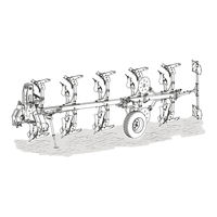
Rabe 2 Series Operating Instructions Manual (118 pages)
Attachment-reversible plough
Brand:
Rabe
| Category:
Farm Equipment
| Size: 35 MB
Table of Contents
Brief Instructions Brief Instructions
3
1 Preparing the Tractor
3
Table of Contents
3
2 Coupling the Implement
4
3 Folding up the Parking Support
5
4 Moving the Plough into the Transport Position
5
Turning the Plough Onto the Right-Hand Side
5
Turning the Combination Wheel into the Transport Position
6
Lifting the Ploughs with Depth Guide Wheel into the Transport Position
7
5 Travelling by Road
7
R Ec T Ify Fau Lt
7
Working Position
8
7 Moving the Plough with Depth Control Wheel into the Working Position
9
8 Removing the Lighting
9
9 Working Values: Working Speed / Working Depth
9
10 Adjusting the Traction Point
10
Plough with Turnbuckle
10
Plough with Hydraulic Frame Slewing
10
Plough with Adjusting Spindle
11
Ploughs with Hydraulic Cylinder
11
12 Adjusting the Working Depth
12
Preparation
12
Depth Adjustment, Depth Control Wheel PS 5
12
Depth Adjustment, Depth Control Wheel PS
12
And Combination Wheel D 30
12
Depth Adjustment, RJR Wheel
13
13 Aligning the Plough Parallel to the Ground
13
14 Adjusting the Incline
14
15 Installing the Lighting
14
16 Adjusting the Working Width
15
17 Adjusting the Track of the Contact or Combination Wheel
15
Operating Instructions
17
Introduction
21
1 Notes on the Operating Instructions
22
2 Symbol Descriptions
22
3 Target Audience of These Operating Instructions
22
4 Intended Use
22
5 For Your Safety
23
General Safety Information
23
Who May Operate the Implement
23
Workplace
23
Safety Instructions - General Usage
23
Safety Instructions - Loading
24
Ballast Calculation
25
Safety Instructions - Coupling/Uncoupling
25
Hydraulic Safety Instructions
25
Pressure Tank Safety Instructions
25
Safety Instructions - Oils and Greases
26
Safety Instructions - Travelling by Road / Transport
26
Safety Instructions - Care, Maintenance and Repair
27
Meanings of the Safety Symbols
28
D es C Rip Tio
29
6 Scope of Delivery
29
Basic Equipment
29
Additional Equipment
29
7 Description of the Implement
30
Description of the Components
31
Description of the Components on the Plough Body
31
8 Description of the Components
33
Tower for Super Albatros
33
Rotation Cylinder
34
Central Lock
34
Adjustment Centre
34
First-Body Working Width Adjustment
34
Traction Point Adjustment
34
Depth Control with Depth Control Wheel or Combination Wheel
35
Frame Swivel Cylinder
35
Working Width Adjustment
35
Add-On Coulter
36
Bodies
36
Round Rod Skimmer
36
Tines
36
Trash Board
36
Vari-Fix Skimmer
36
Disc Coulter
37
Plough Body Stone Protection System
37
Subsoiler Stone Protection System
37
Vari Heavy Duty (VHD) Skimmer
37
Frame Set
38
Leg Reinforcements
38
Lighting Unit
38
Parking Support
38
9 Technical Data
39
Technical Data for Solid Sheet Body
40
Technical Data for Slatted Body
40
Technical Data for Pressure Tank for Tower Suspension
40
Individual Weights of the Additional Equipment
41
Required Hydraulic Connection
41
Required Power Connection
41
Maximum Permissible Dimensions and Weights for Transport by Road
41
Explanation of the Type Designation
42
Type Plate, Mark
42
10 Loading
42
Operation
43
11 Preparing the Tractor
43
Checking Requirements for the Tractor
43
Checking the Tractor's Air Pressure
43
Checking the Track Width
43
Ballast Weight
43
12 Coupling the Implement
44
Notes on Coupling
44
Bottom Link Connection
44
Ball Bush and Guide Cone for Bottom Link Bolt
44
Connection Categories
44
Couple the Bottom Links
45
Couple the Top Link
45
Connect the Hydraulic Lines
46
Couple the Top Link
46
Connect the Hydraulic Lines
47
Connecting the Lighting Cable
47
Required Hydraulic Connections
47
13 Sliding in and Folding up the Parking Support
48
14 Carrying out the Turning Test
49
15 Adjusting the Working Width
50
16 Adjusting the Track of the Contact or Combination Wheel
51
17 Preparing the Machine, Pre-Adjustments
53
Information on the Model
53
Required Preparations
53
General Adjustment Instructions
53
Pre-Adjusting the Traction Point
54
Adjustment Instructions
54
Ploughs with Turnbuckle
54
Ploughs with Hydraulic Frame Slewing
55
Adjusting the Ploughs with Adjusting Spindle
56
Adjusting the Ploughs with Hydraulic Cylinders
56
18 Moving the Plough into the Transport Position
57
Turning the Plough Onto the Right-Hand Side
57
Turn the Ploughs with Combination Wheel into the Transport Position
57
Turning the Combination Wheel into the Transport Position
58
Locking the Central Lock
59
Turning the Plough into the Transport Position
59
Uncoupling the Top Link
59
Lifting the Ploughs with Depth Guide Wheel into the Transport Position
60
19 Travelling by Road
60
Preparations for Travelling by Road
60
Driving Instructions
60
Check before Moving off
61
To the Working Position
61
Removing the Lighting
61
Turn the Plough with Combination Wheel into the Working Position
62
Coupling the Top Link
62
Turning the Plough Onto the Right-Hand Side
62
Unlocking the Central Lock
62
Turning the Combination Wheel into the Working Position
63
Lowering the Plough with Depth Control Wheel into the Working Position
64
Moving the Subsoiler into the Working Position
64
21 Working Information
65
Safety During Operation
65
Depth
66
Working Information
66
Driving Instructions - Turning on Headlands
66
Operational Safety on a Hillside
66
22 Adjustments after Ploughing
67
Adjusting the Working Depth
67
Adjustment Instructions
67
Depth Adjustment, Depth Control Wheel PS 5
67
Preparation
67
PS 30 and Combination Wheel D 30
67
Depth Adjustment, RJR Wheel
68
Aligning the Plough Parallel to the Ground
68
Adjusting the Incline
69
23 Adjustments During Operation
69
Re-Adjusting the Traction Point
69
Adjustment Instructions
69
Re-Adjusting the Traction Point - Plough with Turnbuckle
69
Re-Adjusting the Traction Point - Plough with Hydraulic Frame Slewing
70
Adjusting the Ploughs with Adjusting Spindle
71
Adjusting the Ploughs with Hydraulic Cylinders
71
24 Adjusting the Equipment
72
Adjusting the Trash Boards
72
Adjusting the Subsoiler
72
Adjusting the Disc Coulter
73
Adjusting the Disc Coulter Side Overlap
73
Adjusting the Disc Coulter's Working Depth
73
Adjusting the Stop of the Swing Arm on the Disc Coulter
74
Adjusting the Round Rod Skimmer
75
Adjusting the Skimmer's Working Depth
75
Adjusting the Skimmer with Round Rod's Side Overlap
76
Adjusting the Skimmer with Round Rod's Throwing Angle
77
Adjusting the Vari-Fix Skimmer
77
Adjusting the Vari-Fix Skimmer's Working Depth
77
Vari-Fix Skimmer - Side Overlap
78
Adjusting the Vari Heavy Duty Skimmers
78
Vari Heavy Duty - Adjusting the Working Depth
78
Vari Heavy Duty Skimmers - Lateral Overlap
79
25 After the Work
79
Required Work
79
Install the Lighting
79
26 Parking the Implement
80
Prerequisite
80
Note the Following When Parking
80
Fold the Parking Support out and Adjust the Length
80
Move the Subsoiler into the Storage Position
81
Parking the Ploughs with Combination Wheel
82
Coupling the Top Link
82
Turning the Plough Onto the Right-Hand Side
82
Unlocking the Central Lock
82
Parking the Plough
83
Turning the Combination Wheel into the Storage Position
83
Parking the Ploughs with Depth Control Wheel
83
27 Uncoupling the Implement
84
Disconnecting Hydraulic Connections
84
Disconnect Lighting
84
Uncoupling the Top Link
84
Uncoupling the Bottom Link
85
28 Storage Information
85
29 Cleaning
85
Safety Instructions
85
Cleaning Information
85
30 Troubleshooting
87
31 Replacing the Shear Bolt on Plough Bodies
88
Replace the Shear Bolt
88
Replacing the Shear Bolt - Reinforced, Double Shear Shaft
89
32 Replacing the Vari Heavy Duty (VHD) Shear Bolt
90
33 Replacing the Shear Bolt on the Subsoiler
91
34 Adjust Undercut
92
35 Adjusting the Spring Force of the Tower Suspension
95
M a Int E Na Nc
96
36 Safety Instructions - Maintenance and Repair
96
Safety Instructions - Oils and Greases
96
Who May Carry out Maintenance
97
37 Test Runs During or after Maintenance
97
38 Maintenance Schedule
98
39 Lubricating Points
99
Lubricating Adjusting Spindles
100
40 Re-Tighten All Bolts
101
Key Threaded Connections
101
41 Inspecting the Hydraulics
102
Check the Hydraulic System
102
42 Replacing Wear Parts
103
Replacing Mouldboards
103
Replace the Stripes
103
Replace the Tine
104
Replace the Tines with Reversible Points
104
Replace the Trash Board
105
Replace the Subsoiler
105
Replace the Skimmer Tines and Mouldboard
106
Replace the Disc Coulter
106
43 Replace the Supporting Wheel / Combination Wheel
107
44 Replace the Bulbs in the Lighting
108
Installation
109
45 Installing the Ball Bush on Bottom Link Bolts
109
46 EU Declaration of Conformity
110
47 Ballast Calculation - Combination of the Tractor
110
And Implement
110
Appendix
110
48 Position of the Safety Symbols and Notice Labels
112
49 Tightening Torques for Metric Bolts
113
Tightening Torques for Metric Bolts - Standard Thread
113
50 Notes on Transport and Lighting
114
Notes on Transport
114
51 Electrical Circuit Diagram - Lighting
115
52 Disposing of the Implement
116
Advertisement
Advertisement
Related Products
Rabe Raven HydroAvant 2300
Rabe 230
Rabe 250
Rabe 280
Rabe ADLER DS18 1200
Rabe ADLER DS18 1500
Rabe ADLER DS18 800
Rabe ADLER XT 100
Rabe ADLER XT 130
Rabe Albatros 2 Series
Rabe Categories
Farm Equipment
Food Processor
Drill
Control Unit
Seeders
More Rabe Manuals
Login
Sign In
OR
Sign in with Facebook
Sign in with Google
Upload manual
Upload from disk
Upload from URL