Sign In
Upload
Manuals
Brands
R. Beck Maschinenbau Manuals
Saw
UTK 500
R. Beck Maschinenbau UTK 500 Manuals
Manuals and User Guides for R. Beck Maschinenbau UTK 500. We have
1
R. Beck Maschinenbau UTK 500 manual available for free PDF download: Operating Manual
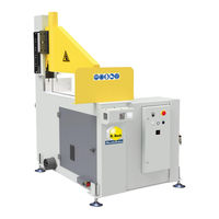
R. Beck Maschinenbau UTK 500 Operating Manual (60 pages)
Under-Table Cross-Cut Saws
Brand:
R. Beck Maschinenbau
| Category:
Saw
| Size: 2 MB
Table of Contents
Table of Contents
6
Liability and Warranty
10
Introduction
11
Legal Notice
11
Illustrations
11
Symbols
11
General Symbols
11
Symbols in Safety Instructions
12
General
13
Structure and Function
13
Standard Equipment
13
Figure 1: Machining Process on the UTK
13
Available Optional Accessories
14
Target Group and Previous Experience
14
Training of the Personnel
14
Requirements for the Operators
15
Accident Prevention
15
General Safety Regulations
15
Safety
16
Basic Safety Instructions
16
Area of Application and Intended Use
16
Prohibition of Misuse
16
Environmental Conditions
16
Modifications and Conversions to the Machine
16
Permissible Workpiece Cross-Sections
17
Figure 2: Permissible Workpiece Cross-Sections UTK 350
17
Figure 3: Permissible Workpiece Cross-Sections UTK 450
17
Figure 4: Permissible Workpiece Cross-Sections UTK 500
17
Figure 5: Permissible Workpiece Cross-Sections UTK 600
17
Machinable Workpiece Lengths
18
Usable Circular Saw Blades
18
Working Areas at the Machine
18
Residual Risks
19
Observe the Environmental Protection Regulations
20
Organisational Measures
20
Personnel Selection and Qualification - Basic Duties
21
Existing Safety Equipment
21
Safety Instructions for Specific Phases of Operation
22
Before Starting Work
22
Normal Operation
23
Special Work Within the Scope of Maintenance Work as Well as Troubleshooting in the Workflow
24
Hazardous Areas on the Under-Table Cross-Cut Saw
25
Figure 6: Danger Zones on the Under-Table Cross-Cut Saw
25
Machine Data
26
Technical Specifications
26
Figure 7: Name Plate
26
Emission Levels
27
Noise Information
27
Noise Emission Values
27
Dust Emission Values
27
Dimensions
28
Utk 350
28
Utk 450
28
Figure 8: UTK 350 Dimensions
28
Figure 9: UTK 450 Dimensions
28
Utk 500
29
Utk 600
29
Figure 10: UTK 500 Dimensions
29
Figure 11: UTK 600 Dimensions
29
Installation and Connection
30
Check Delivery Conditions
30
Transport to the Installation Site
30
Figure 12: Transport on Pallet
30
Figure 13: Lifting off the Pallet
30
Machine Installation
31
Temporary Storage
31
Figure 14: Levelling Via the Feet
31
Lashing in a Transport Vehicle
32
Workplace Requirements
33
Figure 15: Working Positions
33
Electrical Connection
34
Supply Cable and Back-Up Fuse
34
Figure 16: Terminal Box
34
Figure 17: Direction of Rotation
34
Connecting the Extraction System
35
Automatic Switching of the Extraction System
35
Figure 18: Suction Nozzles UTK 500 and 600
35
Figure 19: Earthing Example for Suction Hose
35
Figure 20: Connector
35
Pneumatic Connection
36
Figure 21: Maintenance Unit
36
Components and Controls
37
Figure 22: Components and Controls
37
Commissioning
38
Control Switches and Signal Lamps
38
Figure 23: Control Panel with Switches and Signal Lamps
38
Frequent Switching on and off in Succession
39
Home Position
39
Two-Hand Safety Control
39
Regulating the Lifting Speed
39
Figure 24: Two-Hand Safety Control
39
Figure 25: Adjusting Knob for Lifting Speed
39
Door Interlock with Safety Switch
40
Figure 26: Safety Switch UTK 600 - Door Unlocked
40
Figure 27: Safety Switch UTK 600 - Door Locked
40
Figure 28: Vertically Mounted Safety Switch
40
Installing a Circular Saw Blade
41
Figure 29: Saw Blade Disassembly Via Expansion Cone Flange
41
Figure 30: Direction of Rotation of the Saw Blade
41
Working with the Under-Table Cross-Cut Saw
42
Pneumatic Clamping Guard
42
Function of the Clamping Guard
42
Protective Shield
42
Figure 31: Clamping Guard for Model UTK 600
42
Figure 32: Clamping Guard for Model UTK 350
42
Figure 33: Protective Shield (Standard Version)
42
Lowerable Protective Shield (Pneumatic Option)
43
Full Protection Cover with Viewing Window (Option)
43
Workpiece Fence
43
Figure 34: Optional Pneumatic Protective Shield
43
Figure 35: Full Protection Cover with Viewing Window
43
Figure 36: Workpiece Fence
43
Options in Addition to the Workpiece Fence
44
Safe Workpiece Support
44
Figure 37: Inclined Machine Design
44
Figure 38: Pneumatic Horizontal Clamping Device
44
Figure 39: Roller Conveyor Mounted on One Side
44
Condition of the Circular Saw Blade
45
Sequence of Workpiece Machining
45
Adjust the Lifting Speed
45
Feeding and Positioning the Workpiece
45
Figure 40: Saw Blade Access Door
45
Figure 41: Adjustment Knob for Lifting Speed
45
Figure 42: Manual Positioning System with Flip Stop
45
Triggering the Cutting Stroke
46
Figure 43: Cut Triggering Via Two-Hand Control
46
Interruptions and End of Work
47
Laser Cutting Line Indicator (Option)
47
Particularities When Using the Laser Cutting Line Indicator
47
Figure 44: Laser Unit to Indicate the Cutting Line
47
Figure 45: Visualisation of the Cutting Line on the Workpiece
47
Troubleshooting
48
Behaviour in the Case of a Power Failure
48
General Faults
49
Fault Messages of the Safety PLC
50
Monitoring the End Positions and Valves
50
Illuminated Push Button (L2) for Operating Pressure
50
Maintenance and Inspection
51
Lubrication of the Machine
51
General Maintenance Intervals
51
Check Wear Rail for Circular Saw Blade
52
Fitting and Sawing in the Replacement Wear Rail
52
Figure 46: Wear Rail in the State of Delivery (Example UTK 600)
52
Figure 47: Wear Rail in the Fitted State, Still Without Slot (Example UTK 600)
52
Figure 48: Ready-To-Use Wear Rail with Sawn Slot (Example UTK 600)
52
Tensioning the Drive Belts
53
Adjusting the Correct V-Belt Tension
53
Retensioning the V-Belt on Model UTK 350
53
Retensioning the V-Belt on Model UTK 450
53
Figure 49: Motor Cover Plate Removed
53
Figure 50: V-Belt Tensioning Nuts UTK 350
53
Figure 51: V-Belt Tensioning Nuts UTK 450
53
Retensioning the V-Belt on Model UTK 500
54
Retensioning the V-Belt on Model UTK 600
54
Figure 52: V-Belt Tensioning Nuts UTK 500
54
Figure 53: V-Belt Tensioning Nuts UTK 600
54
Replacing the Drive Belts
55
Readjust Motor Brake
56
Replacing the Motor Brake
56
Figure 54: Brake Adjustment Screw 2.2 / 3.0 / 4.0 Kw
56
Figure 55: Brake Adjustment Screw 5.5 / 7.5 Kw
56
Options and Accessories
57
Utk 350
57
Circular Saw Blades
57
Utk 450
57
Utk 500
58
Circular Saw Blades
58
Options and Accessories
58
Utk 600
58
Disassembly and Scrapping
59
EU - Declaration of Conformity
60
Advertisement
Advertisement
Related Products
R. Beck Maschinenbau UTK 350
R. Beck Maschinenbau UTK 450
R. Beck Maschinenbau UTK 600
R. Beck Maschinenbau Categories
Lifting Systems
Industrial Equipment
Indoor Furnishing
Saw
Tool Storage
More R. Beck Maschinenbau Manuals
Login
Sign In
OR
Sign in with Facebook
Sign in with Google
Upload manual
Upload from disk
Upload from URL