Table of Contents
Advertisement
Quick Links
TRANSLATION OF THE ORIGINAL VERSION
Operating Manual
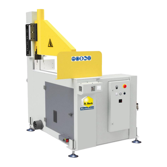
Under-Table Cross-Cut Saws
UTK 350 / UTK 450 / UTK 500 / UTK 600
Under-table cross-cut saws of the UTK series
Machine Types:
Reinhold Beck Maschinenbau GmbH
Im Grund 23 | DE -72505 Krauchenwies
Tel.: +49 (0) 7576 / 962 978 - 0 | Fax: +49 (0) 7576 / 962 978 - 90
E-Mail:
info@beck-maschinenbau.de
| Web:
https://www.beck-maschinenbau.de
Advertisement
Table of Contents
Troubleshooting

Summary of Contents for R. Beck Maschinenbau UTK 350
- Page 1 TRANSLATION OF THE ORIGINAL VERSION Operating Manual Under-Table Cross-Cut Saws UTK 350 / UTK 450 / UTK 500 / UTK 600 Under-table cross-cut saws of the UTK series Machine Types: Reinhold Beck Maschinenbau GmbH Im Grund 23 | DE -72505 Krauchenwies Tel.: +49 (0) 7576 / 962 978 - 0 | Fax: +49 (0) 7576 / 962 978 - 90...
- Page 2 Space for notes: BA_BM_UTK-350-450-500-600_EN_19-23.docx...
- Page 3 Warranty claims: Warranty claims against R. Beck Maschinenbau GmbH are only valid if this handover declaration has been completed, signed and handed over to R. Beck Maschinenbau GmbH and the machine has been properly put into operation. Important: Please read and follow the instructions in chapter 1 ”Liability and Warranty“.
- Page 4 Space for notes: BA_BM_UTK-350-450-500-600_EN_19-23.docx...
- Page 5 Warranty claims: Warranty claims against R. Beck Maschinenbau GmbH are only valid if this handover declaration has been completed, signed and handed over to R. Beck Maschinenbau GmbH and the machine has been properly put into operation. Important: Please read and follow the instructions in chapter 1 ”Liability and Warranty“.
-
Page 6: Table Of Contents
Table of contents Liability and warranty ........................... 10 Introduction..............................11 Legal notice ..................................11 Illustrations ..................................11 Symbols ................................ 11 General Symbols ................................11 Symbols in safety instructions ............................12 General ................................. 13 Structure and function ..............................13 Standard equipment..............................13 Available optional accessories ............................ - Page 7 6.2.2 Noise emission values ............................27 6.2.3 Dust emission values ............................. 27 Dimensions ..............................28 UTK 350 ..................................28 UTK 450 ..................................28 UTK 500 ..................................29 UTK 600 ..................................29 Installation and connection .......................... 30 Check delivery conditions ............................. 30 Transport to the installation site ..........................
- Page 8 Tensioning the drive belts ............................. 53 13.4.1 Adjusting the correct V-belt tension ........................53 13.4.2 Retensioning the V-belt on model UTK 350 ......................53 13.4.3 Retensioning the V-belt on model UTK 450 ......................53 13.4.4 Retensioning the V-belt on model UTK 500 ......................54 13.4.5...
- Page 9 Figure 30: direction of rotation of the saw blade ..........................41 Figure 31: clamping guard for model UTK 600............................. 42 Figure 32: clamping guard for model UTK 350............................. 42 Figure 33: protective shield (standard version) ........................... 42 Figure 34: optional pneumatic protective shield ..........................43 Figure 35: full protection cover with viewing window .........................
-
Page 10: Liability And Warranty
Liability and warranty When purchasing a machine or work equipment (hereinafter referred to as “machine”), the General Terms and Conditions of Sale and Delivery of Reinhold Beck Maschinenbau GmbH generally apply. These are provided to the purchaser or operator at the latest when the contract is concluded. ... -
Page 11: Introduction
2 Introduction The purpose of this document is to acquaint the user with the machine and enable him to use it to the full extent of its intended capabilities. Additionally it contains important information to operate the machine safely, properly and economically. Observance of the manual helps to avoid hazards, reduce repair costs and downtimes and increase the reliability and service life of the machine. -
Page 12: Symbols In Safety Instructions
Symbols in safety instructions Symbol Safety instruction General danger symbol, which requires the highest attention! Failure to observe may result in damage to the equipment, serious injury or even death. Warning of possible danger from forklift traffic! Non-observance may result in life-threatening injuries. Warning indicates a possible hazard under suspended loads! Non-observance may result in life-threatening injuries. -
Page 13: General
4 General This under-table cross-cut saw was produced by Beck Maschi- nenbau GmbH according to the current state of the art and placed on the market as a complete machine. All legal and nor- mative regulations have been complied with. The four models are designed for different saw blade diameters (350, 450, 500 and 600 mm). -
Page 14: Available Optional Accessories
• Spraying device (micro cooler ) for cutting aluminium • UTK 350 and UTK 450 only: Machine in 10° inclined design, for easier positioning of workpieces to the workpiece fence • UTK 500 and UTK 600 only: Unhindered feeding and positioning of workpieces by means of a pneumatically operated protective shield that can be raised and lowered •... -
Page 15: Requirements For The Operators
Requirements for the Operators • The under-table cross-cut saw may only be operated by trained personnel who have also read this manual. • Inspection, maintenance, cleaning and repair may only be performed by technical specialists with product-specific training and mechanical and/or electrical training. •... -
Page 16: Safety
Improper use can lead to danger to persons and to a defect or damage to the machine. The four under-table cross-cut saws UTK 350, UTK 450, UTK 500, UTK 600 are used exclusively for cutting solid wood and wood-like materials to length. -
Page 17: Permissible Workpiece Cross-Sections
UTK model or saw blade diameter correspond to the following ranges: UTK 350: UTK 450: SECTIONAL DIAGRAM WORKPIECE WIDHT WORKPIECE HEIGHT WORKPIECE WIDHT Figure 2: permissible workpiece cross-sections UTK 350 Figure 3: permissible workpiece cross-sections UTK 450 UTK 500: SECTIONAL DIAGRAM Note: All dimensions in millimetres WORKPIECE WIDHT WORKPIECE HEIGHT... -
Page 18: Machinable Workpiece Lengths
• Workpiece machining is to be carried out with carbide-tipped circular saw blades. • The decisive factor here is the suitability for machining across the grain. The following circular saw blades are to be used for the four UTK models: Model UTK 350 UTK 450 UTK 500 UTK 600 Circular saw blade Ø... -
Page 19: Residual Risks
5.1.9 Residual risks The machine is built according to the latest state of the art and the recognised safety rules. Nevertheless, the use of the machine may cause danger to life and limb of the user or third parties or damage to the machine and other equipment. -
Page 20: Observe The Environmental Protection Regulations
Make sure that no unauthorised persons are in the area of the machine. Be aware of the risk of injury from flying tool parts in the event of tool breakage. Therefore wear protective goggles. Be aware of the risk of injury from flying workpiece parts and chips, splinters and dust coming out of the machine. -
Page 21: Personnel Selection And Qualification - Basic Duties
Use personal protective equipment as necessary or required by regulations. Do not make any modifications, additional attachments or conversions to the machine without the manu- facturer's approval! This will compromise safety and invalidate the manufacturer's warranty and any liabil- ity claim. The same also applies to the installation and adjustment of safety devices and valves and to welding work on load-bearing part. -
Page 22: Safety Instructions For Specific Phases Of Operation
Safety instructions for specific phases of operation Defects and damage to the machine are to be reported immediately after detection. Any mode of operation that compromises safety is prohibited! Sufficient lighting (at least 500 lux) around the machine must be ensured! 5.3.1 Before starting work Protective equipment: Wear personal protective equipment (safety goggles, safety shoes, ear protection, dust mask) and close-fitting clothing and, if necessary, a hair net! Take off watches, necklaces and other... -
Page 23: Normal Operation
5.3.2 Normal operation Guards: Take measures to ensure that the machine can only be operated in a safe and functional condi- tion. Only operate the machine when all guards and safety-related devices such as - detachable guards, - emergency stop devices, - noise insulations, - extraction system are available and functional... -
Page 24: Special Work Within The Scope Of Maintenance Work As Well As Troubleshooting In The Workflow
5.3.3 Special work within the scope of maintenance work as well as troubleshooting in the workflow Observe maintenance and inspection activities prescribed in chapter 13 “Maintenance and inspection”! These activities, as well as all other repair work, may only be carried out by qualified personnel! For all work concerning operation, production adjustment, conversion or setting of the machine and its safety-related equipment as well as maintenance and repair, observe switch-on and switch-off procedures according to the operating manual and instructions for maintenance work! -
Page 25: Hazardous Areas On The Under-Table Cross-Cut Saw
Hazardous areas on the under-table cross-cut saw Various hazards can arise on the under-table cross-cut saw. Particular attention must be paid to the danger areas listed in this section. Here, there is an acute potential for danger ranging from minor and serious injuries to fatalities! Side view: Top view:... -
Page 26: Machine Data
Machine data Technical specifications Model UTK 350 UTK 450 UTK 500 UTK 600 Maximum cutting height 100 mm 115 mm 140 mm 200 mm Maximum cutting width 230 mm 340 mm 390 mm 800 mm Circular saw blade Ø 350 mm Ø... -
Page 27: Emission Levels
Emission levels 6.2.1 Noise information The values given are emission levels and therefore do not necessarily represent safe workplace values. Although there is a correlation between emission and immission levels, it cannot be reliably deduced whether additional precautionary measures are necessary or not. Factors that may affect the current immission level at the workplace include the duration of exposure, the nature of the workspace, other noise sources, etc., e.g. -
Page 28: Dimensions
7 Dimensions UTK 350 Figure 8: UTK 350 dimensions Subject to design and dimensional changes! UTK 450 1000 Figure 9: UTK 450 dimensions Subject to design and dimensional changes! BA_BM_UTK-350-450-500-600_EN_19-23.docx... -
Page 29: Utk 500
UTK 500 1145* 1200 *) 1335 mm with pneumatic protection shield (option) Figure 10: UTK 500 dimensions Subject to design and dimensional changes! UTK 600 1560* 1150 *) 1660 mm with pneumatic protection shield (option) Figure 11: UTK 600 dimensions Subject to design and dimensional changes! BA_BM_UTK-350-450-500-600_EN_19-23.docx... -
Page 30: Installation And Connection
Installation and connection Check delivery conditions Check the consignment for completeness and possible transport damage. In case of transport damage, please keep the packaging and inform the shipping company and the manufacturer immediately! Later complaints can- not be accepted. Transport to the installation site Transport the transport unit to the installation site of the under-table cross-cut saw. -
Page 31: Machine Installation
Machine installation Ensure that there is sufficient space around the machine. To ensure that maintenance, repair, inspection and cleaning work can also be carried out without obstructions, a free space of at least 1.0 m must be allowed on all four sides of the machine (including roller conveyors) when setting up. -
Page 32: Lashing In A Transport Vehicle
Lashing in a transport vehicle For later transport in a transport vehicle, the under-table cross-cut saw (as delivered) must be properly bolted to a pallet via the holes in the four feet and lashed to the floor of the loading area of the vehicle with at least two lashing straps. -
Page 33: Workplace Requirements
Workplace requirements The effective space requirement depends on the external dimensions of the machine (see chapter 6.2.3) and the dimensions of the workpieces to be processed. In general, provide sufficient space around the machine and also calculate the space required for setting work, the operating and auxiliary personnel as well as for the infeed and outfeed of long workpieces. -
Page 34: Electrical Connection
Electrical connection The electrical connection must be carried out by an authorised electrician! The fault loop impedance and the suitability of the overcurrent protection device must be checked at the installation site of the machine! The electrical circuit diagrams are located in the control cabinet on the front of the machine. Please observe the nominal voltage 400 VAC / 50 Hz (3 phases / N / PE)! •... -
Page 35: Connecting The Extraction System
Connecting the extraction system • The machine must be connected to an effective extrac- tion system on site. • Depending on the model, the machine has 2 or 3 suc- tion nozzles. You will find the number and respective diameters of the suction nozzles for your machine model in the section ... -
Page 36: Pneumatic Connection
Pneumatic connection For the guard and the saw stroke to function as intended, the under-table cross-cut saw must be connected to a compressed air supply by a qualified person. Compressed air connection: • The connection is made via the quick coupling (K) on the maintenance unit mounted on the machine body. -
Page 37: Components And Controls
Components and controls Figure 22: components and controls Pos. Description Pos. Description Main switch (lockable) Suction nozzles Control cabinet with control switches Workpiece fence Air connection with maintenance unit Adjusting knob for lifting speed Emergency stop button Door safety switch with interlock Sawing table Access door for saw blade change Protective shield... -
Page 38: Commissioning
Commissioning Carefully read and observe the operating manual and the safety instructions 5 before commissioning. Before switching on, always ensure that • the floor around the machine is clean and free of disturbing parts and workpieces, • no persons are in the danger zones of the machine, •... -
Page 39: Frequent Switching On And Off In Succession
10.2 Frequent switching ON and OFF in succession Avoid switching on and off several times in quick succession, as a bandsaw machine is not designed to be switched on and off constantly. This may cause an overload, which will trip the fuses or the motor protection device. -
Page 40: Door Interlock With Safety Switch
In addition, a sticker on the switch shows the correct direction of rotation of the knurled screw for unlocking and locking. The Figure 28 on the left shows the vertically mounted safety switches of the UTK 350, 450 and 500 models. Figure 28: vertically mounted safety switch BA_BM_UTK-350-450-500-600_EN_19-23.docx... -
Page 41: Installing A Circular Saw Blade
10.7 Installing a circular saw blade To ensure safe working without incidents, the installation resp. change of a circular saw blade must be carried out properly. To install the circular saw blade, proceed as described below. Caution: Cutting hazard! Only change saw blades when wearing protective gloves! •... -
Page 42: Working With The Under-Table Cross-Cut Saw
Remark: The clamping guards of the UTK 500 and UTK 600 models are equipped with a suction nozzle on the upper side, whereas the UTK 350 and UTK 450 models are equipped with a suction nozzle on the lower right side of the guard on the machine column (see example figures below). -
Page 43: Lowerable Protective Shield (Pneumatic Option)
11.3 Lowerable protective shield (pneumatic option) Measures to secure access to the saw blade are prescribed in the DIN EN 1870-10 standard for under-table cross-cut saws and serve to ensure the safety of the user. For the UTK 500 and UTK 600 models, a pneumatically operated protective shield is available as an option. -
Page 44: Options In Addition To The Workpiece Fence
Remark: The pneumatic horizontal clamping device Remark: The option "inclined machine design" is cannot be combined with the optional pneumatically only available for the two models UTK 350 and UTK actuated safety shield (see 0). 450. Important note: When handling the pneumatic horizontal clamping device, also observe the additional danger of crushing (see “Hazardous areas”... -
Page 45: Condition Of The Circular Saw Blade
11.7 Condition of the circular saw blade • Always check the condition of the circular saw blade before starting work. To do this, release the access door to the circular saw blade for opening by first unlocking the door safety switch (see section 10.6). •... -
Page 46: Triggering The Cutting Stroke
11.8.3 Triggering the cutting stroke Simultaneously press both buttons of the two-hand safety control and keep them pressed until the cut is completed and the saw blade has completely lowered under the table again. Sequence when pressing both buttons (standard): 1. -
Page 47: Interruptions And End Of Work
11.9 Interruptions and end of work • Always switch off the circular saw blade drive even in the event of short interruptions. • In case of longer interruptions or at the end of work, additionally switch off the main switch and secure it with a padlock against unauthorised restarting. -
Page 48: Troubleshooting
Troubleshooting • Before any troubleshooting, switch off the main switch and secure it with a padlock. • After each troubleshooting, all guards and safety devices must be put back into operation and checked for functionality! • Only carry out troubleshooting work if you are familiar with the operation of the machine and if you are authorised and have received safety training. -
Page 49: General Faults
12.2 General faults Fault Possible cause Remedy → Check connections (electrician!) No voltage → Replace fuse (electrician!) Backup fuse defective → Turn the main switch on Main switch is turned off → Replace switch (electrician!) Main switch defective → Replace push button (electrician!) Push button for drive defective →... -
Page 50: Fault Messages Of The Safety Plc
12.3 Fault messages of the safety PLC Other operating states are monitored by the safety PLC and signalled via the signal lamp (L1). 12.3.1 Monitoring the end positions and valves Faults and errors are signalled by repeated flashing sequences of the signal lamp (L1) installed in the control panel of the machine (see also ... -
Page 51: Maintenance And Inspection
Maintenance and inspection Before any maintenance and inspection work is carried out, chapter 5 “Safety” must be read carefully and observed! Before maintenance and repair work, switch off the main switch and lock it with a padlock! Operational malfunctions caused by insufficient or improper maintenance can result in very high repair costs and long machine downtimes. -
Page 52: Check Wear Rail For Circular Saw Blade
Model W x T x L Art. No. Model W x T x L Art. No. UTK 350 50 x 12 x 294,5 mm 80 006 018 02 UTK 500 50 x 12 x 442 mm 80 004 018 02... -
Page 53: Tensioning The Drive Belts
Recommendation: You can achieve the optimum V-belt tension with a special belt tension gauge. 13.4.2 Retensioning the V-belt on model UTK 350 • The motor of model UTK 350 is mounted with the 3 fastening screws (B) via the motor flange. -
Page 54: Retensioning The V-Belt On Model Utk 500
13.4.4 Retensioning the V-belt on model UTK 500 • The motor of the UTK 500 model is fixed to a mount- ing plate with the 4 fastening screws (B). • To tension the belts, the motor 4 fastening screws (B) must be loosened slightly so that the motor can be moved in the slotted holes of the mounting plate. -
Page 55: Replacing The Drive Belts
Please refer to the following table for the number and type designations of the belts for your UTK model: Model V-belt type Qty. Model V-belt type Qty. UTK 350 Optibelt XPZ 862 UTK 500 Optibelt XPZ 900 UTK 450 Optibelt XPZ 987 UTK 600 Optibelt XPZ 1337 ... -
Page 56: Readjust Motor Brake
13.6 Readjust motor brake Check the brake function of the main motor monthly → If the machine no longer comes to a standstill within 10 seconds when braking, the motor brake must be readjusted. The motor brake may only be readjusted by qualified personnel! The procedure for readjustment varies depending on the motor power of the installed drive motor. -
Page 57: Options And Accessories
The use of other accessories or spare parts can cause injury to persons and damage to the machine. The manufacturer accepts no liability for any damage resulting from the use of non-prescribed accessories and spare parts or additional components from third parties! 14.1 UTK 350 14.1.1 Circular saw blades Article Description Art. -
Page 58: Utk 500
14.3 UTK 500 14.3.1 Circular saw blades Article Description Art. No. HM circular saw blade for wood 500 x 5.6 x 3.6 x 30 Z84 WZ UTK 18.02-H HM saw blade for aluminium 500 x 4.0 x 3.4 x 30 Z120 UTK 18.02-ALU 14.3.1 Options and accessories Article... -
Page 59: Disassembly And Scrapping
Disassembly and scrapping When dismantling and scrapping the machine, the current EU regulations or the respective regulations and laws of the country of operation, which are prescribed for proper dismantling and disposal, must be observed. The aim is to dismantle the machine and its various materials and components properly, to recycle all possible parts and to dispose of non-recyclable components in the most environmentally friendly way. -
Page 60: Eu - Declaration Of Conformity
Telefax: +49 (0) 7576 / 962 978 - 90 DE 72505 Krauchenwies hereby declares that the manufactured machine UNDER-TABLE CROSS-CUT SAW UTK 350, UTK 450, UTK 500, UTK 600 Machine-No.: ......Year of manufacture: ..... in the version provided complies with the following directives:...
Need help?
Do you have a question about the UTK 350 and is the answer not in the manual?
Questions and answers