Sign In
Upload
Manuals
Brands
Quanmax Manuals
Industrial PC
KEEX-1760 Series
Quanmax KEEX-1760 Series Manuals
Manuals and User Guides for Quanmax KEEX-1760 Series. We have
1
Quanmax KEEX-1760 Series manual available for free PDF download: User Manual
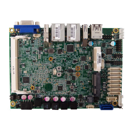
Quanmax KEEX-1760 Series User Manual (60 pages)
Intel Embedded Compact Extended Form Factor with Intel BayTrail Processors
Brand:
Quanmax
| Category:
Industrial PC
| Size: 1 MB
Table of Contents
Table of Contents
3
Content
3
Figures
5
Tables
6
Safety Instructions
8
Before You Begin
8
When Working Inside a Computer
8
Preventing Electrostatic Discharge
9
Preface
11
How to Use this Guide
11
Unpacking
11
Regulatory Compliance Statements
11
Warranty Policy
12
Maintaining Your Computer
13
Chapter 1 Introduction
16
Overview
16
Product Specifications
17
System Block Diagram
18
Figure 1 Block Diagram
18
Table 1 KEEX-1760 Series Specification
18
Mechanical Dimensions
19
Figure 2 Mechanical Dimensions
19
Chapter 2 Hardware Settings
20
Overview
20
Figure 3 Jumper Connector
20
Jumper Settings and Pin Definitions
21
Figure 4 Jumper and Connector Locations
21
Jumper Settings
22
Table 2 Jumper List
22
Table 3 JP1 RTC Reset Selection
22
Table 4 JP2 Mpcie Activity LED Indication
22
Table 5 JP4 Backlight Enable Selection
22
Table 6 JP5 Panel & Backlight Power Selection
23
Table 7 JP6 USB Power Selection
23
Table 8 JP7 at / ATX Power Mode Selection
23
Table 9 JP8 ME F/W Selection
23
Internal Connector Pin Assignment
24
Table 10 BAT1 CR2032 Battery Power Input Wafer
25
Table 11 COM1~2 RS-232/422/485 Port 1 Wafer
25
Table 12 COM3~6 RS-232 Port 2 Wafer
25
Table 13 CN1 DC12V Power Input Wafer
25
Table 14 CN2 PS/2 Keyboard / Mouse Wafer
26
Table 15 CN3 HDD Power Output Wafer
26
Table 16 CN9 Audio Input / Output Pin Header
26
Table 17 CN10 SIM Interface Wafer for Mpcie2
26
Table 18 CN11 Right Channel 3W Audio AMP Output Wafer
27
Table 19 CN12 Left Channel 3W Audio AMP Output Wafer
27
Table 20 CN13 Digital Input / Output Wafer
27
Table 21 CN14 Backlight Power Output Wafer
27
Table 22 FAN1 DC5V FAN Wafer
28
Table 23 FP1 Front Panel 1 Pin Header
28
Table 24 FP2 Front Panel 2 Pin Header
28
Table 25 LVDS1 Secondary 18/24-Bit, 2-Channel LVDS Panel Connector
28
Table 26 Mpcie1 Mini-PCI Express V1.2 Socket 1 (Full Size)
29
Table 27 MSATA1 Serial ATA Port-1 Msata Socket (Full Size)
30
Table 28 SATA1 Serial ATA Port 0 Connector
30
Table 29 CN15 USB2.0 Port Wafer
30
Table 30 CN16 USB2.0 Port 8, 9 Pin Header
31
Rear Panel Pin Assignments
32
Figure 5 Rear Panel IO
32
Table 31 Rear Panel Connector List
32
Table 32 CN7 Gbe LAN1 RJ-45 Connector
32
Table 33 CN8 Gbe LAN2 RJ-45 Connector
32
Table 34 CN6 USB2.0 Port 2,3 Type-A Connector
32
Table 35 USB1 USB3.0 Port 0 Connector
33
Table 36 HDMI1 HDMI Connector
33
Table 37 VGA1 DB-15 VGA Connector
33
Chapter 3 System Installation
34
Memory Module Installation
34
Figure 6 Align the SO-DIMM Memory Module with the Onb Oard Socket
34
Figure 7 Press down on the SO-DIMM Memory Module to Lock It in Place
35
Chapter 4 AMI BIOS Setup
36
Overview
36
Main Menu
37
Table 38 KEEX-1760 BIOS Main Menu
37
Table 39 KEEX-1761 BIOS Main Menu
38
Table 40 KEEX-1762 BIOS Main Menu
39
Advanced Menu
40
Table 41 Advanced Menu
40
Table 42 Advanced Menu - Display Configuration
41
Table 43 Advanced Menu - Super IO Configuration
42
Table 44 Ad Vanced Menu - Super IO Configuration - Serial Port
42
Table 45 Ad Vanced Menu - Super IO Configuration - Serial Port
43
Table 46 Ad Vanced Menu - Super IO Configuration - Serial Port
44
Table 47 Ad Vanced Menu - Super IO Configuration - Serial Port
45
Table 48 Ad Vanced Menu - Super IO Configuration - Serial Port
46
Table 49 Ad Vanced Menu - Super IO Configuration - Serial Port
46
Table 50 Advanced Menu -CPU Advanced Configuration
47
Table 51 Advanced Menu -SATA Configuration
47
Table 52 Advanced Menu -USB Configuration
48
Table 53 Advanced Menu -DIO Configuration
49
Table 54 Advanced Menu -H/W Monitor
50
Table 55 Power Configuration
51
Boot Menu
52
Table 56 Boot Menu
52
Security Menu
53
Save & Exit Menu
53
Table 57 Security Menu
53
Table 58 Save & Exit Menu
53
Chapter 5 Driver Installation
55
Advertisement
Advertisement
Related Products
Quanmax KEEX-5100 Series
Quanmax KPC-1561
Quanmax KPC-1006RT
Quanmax KUBE-8030
Quanmax KPC-1560
Quanmax KEEX-6100
Quanmax KEEX-4030
Quanmax KEEX-2010
Quanmax KEEX-7100 Series
Quanmax KEEX-1850 Series
Quanmax Categories
Desktop
Touch Panel
Motherboard
Computer Hardware
Monitor
More Quanmax Manuals
Login
Sign In
OR
Sign in with Facebook
Sign in with Google
Upload manual
Upload from disk
Upload from URL