Sign In
Upload
Manuals
Brands
Qsan Technology Manuals
Storage
XCubeFAS 3126
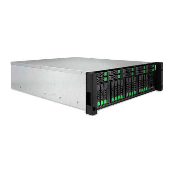
Qsan Technology XCubeFAS 3126 Manuals
Manuals and User Guides for Qsan Technology XCubeFAS 3126. We have
1
Qsan Technology XCubeFAS 3126 manual available for free PDF download: Hardware Manual
Qsan Technology XCubeFAS 3126 Hardware Manual (90 pages)
Brand:
Qsan Technology
| Category:
Storage
| Size: 4.09 MB
Table of Contents
Table of Contents
3
Announcement
4
Notices
9
Regulatory Statements
10
FCC Statement
10
CE Statement
10
UL Statement
10
Preface
15
About this Manual
15
Related Documents
15
Technical Support
16
Information, Tip, and Caution
16
Conventions
17
Product Overview
18
Introduction to Xcubefas Series
18
Hardware Specifications
18
Figure 1-1 XF3126 Form Factors
19
Table 1-1 XF3126 Hardware Specifications
19
Package Contents
21
System Components Overview
22
Front Panel
22
Figure 2-1 System Controls and Indicators
22
Table 2-1 Descriptions of the System Controls and Indicators Leds
23
Figure 2-2 Disk Drive Numbering
24
Figure 2-3 Disk Drive Indicators of SFF Disk Drive Tray
25
Table 2-2 Descriptions of Disk Drive Leds
25
Rear Panel
26
Figure 2-4 Rear Panel Layout
26
Table 2-3 Rear Panel Layout
26
Figure 2-5 Components of Controller Module
27
Table 2-4 Description of Controller Module Components
27
Figure 2-6 Controller Leds
28
Table 2-5 Descriptions of Controller Leds
28
Power Supply Units
29
Figure 2-7 Location of the Power Supply Unit
30
Figure 2-8 Components of the Power Supply Unit
30
Table 2-6 Location of the Power Supply Unit
30
Cache-To-Flash Memory Protection
31
Table 2-7 Components of the Power Supply Unit
31
Table 2-8 Descriptions of the Power Supply Unit LED
31
Figure 2-9 Location of the Cache-To-Flash Module
32
Table 2-12 Components of Cache-To-Flash Modules
32
Figure 2-10 Cache-To-Flash Workflow
33
Figure 2-11 Flash Module Leds and Button
33
Optional) Host Cards
34
Table 2-13 Descriptions of Flash Module Leds and Button
34
Figure 2-12 Host Card Installation Slots
35
Table 2-14 Host Card Installation Slots of a Controller
35
Figure 2-13 2-Port 32Gb Fibre Channel Host Card (SFP28) Leds
36
Table 2-15 Descriptions of 2-Port 32Gb Fibre Channel Host Card (SFP28) Leds
36
Figure 2-14 4-Port 16Gb Fibre Channel Host Card (SFP+) Leds
37
Table 2-16 Descriptions of 4-Port 16Gb Fibre Channel Host Card (SFP+) Leds
37
Figure 2-15 2-Port 16Gb Fibre Channel Host Card (SFP+) Leds
38
Table 2-17 Descriptions of 2-Port 16Gb Fibre Channel Host Card (SFP+) Leds
38
Figure 2-16 2-Port 25Gbe Iscsi Host Card (SFP28) Leds
39
Table 2-18 Descriptions of 2-Port 25Gbe Iscsi Host Card (SFP28) Leds
39
Figure 2-17 4-Port 10Gbe Iscsi Host Card (SFP+) Leds
40
Table 2-19 Descriptions of 4-Port 10Gbe Iscsi Host Card (SFP+) Leds
40
Figure 2-18 2-Port 10GBASE-T Iscsi Host Card (RJ45) Leds
41
Table 2-20 Descriptions of 2-Port 10GBASE-T Iscsi Host Card (RJ45) Leds
41
Installing the System Hardware
42
Installation Checklist
42
Table 3-1 Installation Checklist
42
Installing Disk Drives into the Trays
43
Table 3-2 Optional Items for Installation
43
Figure 3-1 Front Side Components of SFF Disk Drive Trays
44
Table 3-3 Front Side Components of SFF Disk Drive Trays
44
Figure 3-2 Unlock and Open the Carrier Handle of a Disk Drive Tray (SFF)
45
Figure 3-3 Hold the Carrier Handle and Pull out the Disk Drive Tray (SFF)
45
Installing the Slide Rails
46
Figure 3-4 Align a Disk Drive & Install into a Tray (SFF-To-SFF)
46
Figure 3-5 First Step of the Slide Rails Installation
47
Figure 3-6 Second Step of the Slide Sails Installation
48
Figure 3-7 Third Step of the Slide Rails Installation
48
Installing the Trays into the System
49
Figure 3-8 Fourth Step of the Slide Sails Installation
49
Connecting the System to a Host
50
Figure 3-9 Install a Tray into the System and Lock the Release Button Lock (SFF)
50
Connecting Power Cords
51
Figure 3-10 Cabling Example
51
Powering on the System
52
Figure 3-11 the Location of Connecting Power Cords
52
Figure 3-12 Press the Power Button One Time to Power on the System
52
Discover and Carry out the System
53
Powering off the System
53
Figure 3-13 Power off the System Via Web UI
53
Optional) Connecting a UPS
54
Figure 3-14 Power off the System by Power Button
54
Figure 3-15 Location for the UPS System Connection
54
Optional) Connecting the USB LCM
55
Optional) Wake-On-LAN
55
Quick Maintenance
56
Removing / Installing Controller Module
56
Figure 4-1 Controller Module Failure Warning
57
Figure 4-2 Controller Module Installed Successfully
58
Figure 4-3 Change Operation Mode to Dual Controller
58
Installing Optional Memory Modules
59
Figure 4-4 Memory Module Slot Number
60
Table 4-2 Optional Memory Module Installation Sequence
61
Removing / Installing Power Supply Unit
62
Figure 4-5 PSU Failure Warning
62
Figure 4-6 Mechanical Components of the PSU
63
Table 4-3 Mechanical Components of the PSU
63
Figure 4-7 Removing the Power Supply Unit
64
Figure 4-8 Installing the Power Supply Unit
64
Removing / Installing Fan Module
65
Figure 4-9 PSU Installed Successfully
65
Figure 4-10 Location of each Fan Module
66
Table 4-6 Location of each Fan Module
66
Figure 4-11 Fan Module Failed Warning
67
Figure 4-12 Removing the Fan Module
67
Figure 4-13 Installing the Fan Module
68
Figure 4-14 Fan Module Installed Successfully
68
Removing / Installing Cache-To-Flash Module
69
Figure 4-15 Cache-To-Flash Module Failed Warning
69
Figure 4-16 Removing the Cache-To-Flash Module
70
Figure 4-17 Installing the Cache-To-Flash Module
71
Figure 4-18 Cache-To-Flash Module Installed Successfully
71
Removing / Installing Optional Host Cards
72
Figure 4-19 Example of a Failed Port on the 10Gbe Iscsi Host Card
72
Figure 4-20 Removing the Host Card
73
Figure 4-21 Install the Dummy Host Card Cage
73
Figure 4-22 Removing the Host Card
74
Figure 4-23 Connection and Status of the Host Cards
75
Deployment Types and Cabling
76
Deployment Types
76
Cabling the System
76
Table 5-1 Deployment Types
76
Figure 5-1 One Host / One Xcubefas / Single Path
77
Figure 5-2 One Host / One HBA / Two Switches / One Xcubefas / Dual Path
78
Figure 5-3 Two Hosts / One HBA Per Host / Two Switches / One Xcubefas / Dual Path
79
Support and Other Resources
80
Getting Technical Support
80
Figure 6-1 Download Service Package
81
Online Customer Support
82
Figure 6-2 Appearance of a Console Cable
82
Figure 6-3 Connect the Console Cable
82
Figure 6-4 the Procedures of Setup Serial Console by Hyperterminal
84
Accessing Product Updates
86
Figure 6-5 the Procedures of Setup Serial Console by Putty
86
Documentation Feedback
87
Appendix
88
End-User License Agreement (EULA)
88
Advertisement
Advertisement
Related Products
Qsan Technology XCubeFAS Series
Qsan Technology XCubeFAS 2026
Qsan Technology P300H61
Qsan Technology P300H71
Qsan Technology XCubeDAS XD5312D
Qsan Technology XCubeDAS XD5312S
Qsan Technology XCubeDAS XD5316D
Qsan Technology XCubeDAS XD5316S
Qsan Technology XCubeDAS XD5324D
Qsan Technology XCubeDAS XD5324S
Qsan Technology Categories
Storage
More Qsan Technology Manuals
Login
Sign In
OR
Sign in with Facebook
Sign in with Google
Upload manual
Upload from disk
Upload from URL