QRP Labs QCX-mini Manuals
Manuals and User Guides for QRP Labs QCX-mini. We have 3 QRP Labs QCX-mini manuals available for free PDF download: Assembly Instructions Manual, Operating Instructions Manual

QRP Labs QCX-mini Assembly Instructions Manual (133 pages)
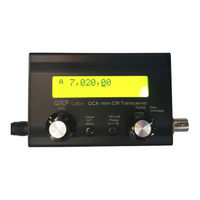
5W CW Transceiver kit
Brand: QRP Labs
|
Category: Transceiver
|
Size: 11 MB
Table of Contents
Advertisement
QRP Labs QCX-mini Assembly Instructions Manual (121 pages)
Brand: QRP Labs
|
Category: Transceiver
|
Size: 12 MB
Table of Contents

QRP Labs QCX-mini Operating Instructions Manual (52 pages)
5W CW Transceiver kit
Brand: QRP Labs
|
Category: Transceiver
|
Size: 0 MB
Table of Contents
Advertisement
Advertisement