Q2 Q2A Manuals
Manuals and User Guides for Q2 Q2A. We have 1 Q2 Q2A manual available for free PDF download: Technical Manual

Q2 Q2A Technical Manual (866 pages)
Brand: Q2
|
Category: Controller
|
Size: 85 MB
Table of Contents
-
Receiving19
-
Nameplate20
-
Decrease Noise110
-
Wiring Checklist116
-
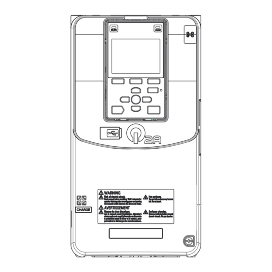
Operator Display124
-
Keypad Operation131
-
Set Data to Log144
-
Auto-Tuning147
-
EZ Tuning152
-
Control Tuning153
-
Test Run156
-
Load Test Run156
-
EMC Directive190
-
UL Standards199
-
Area of Use199
-
对应中国Rohs指令223
-
Message Format236
-
Enter Command242
-
Self-Diagnostics242
-
Error Codes257
-
Troubleshooting259
-
Faults266
-
Fault Reset307
-
Command311
-
Energized312
-
PID Output Fault313
-
Inspection318
-
Maintenance321
-
Wire a New Drive350
-
Disposal357
-
Specifications361
-
Drive Duty Modes362
-
Drive Derating375
-
Drive Watt Loss380
-
Parameter List411
-
B: APPLICATION415
-
B3: SPEED SEARCH417
-
B4: TIMER418
-
B5: PID CONTROL419
-
B9: ZERO SERVO423
-
C: Tuning424
-
C2: Jerk Control424
-
D: REFERENCE429
-
E: Motor433
-
F: Options437
-
F1: Encoder437
-
F2: Analog Input439
-
F7: Ethernet445
-
H: Terminals448
-
H5: Modbus Ports462
-
L: Protection466
-
L7: Torque Limit472
-
11.10 N: SPECIAL475
-
11.11 O: KEYPAD481
-
O5: DATA LOGGER485
-
T0: Tune Mode488
-
T2: Pm Motor489
-
T3: Asr490
-
U1: Status491
-
U2: Fault493
-
U4: Maintenance495
-
U5: Pid498
-
U6: Advanced499
-
Class508
-
B: APPLICATION535
-
B3: SPEED SEARCH550
-
B4: TIMER558
-
B5: PID CONTROL560
-
B9: ZERO SERVO582
-
C: Tuning584
-
C2: Jerk Control589
-
D: REFERENCE608
-
E: Motor629
-
F: Options649
-
F1: Encoder649
-
F2: Analog Input656
-
H: Terminals687
-
H5: Modbus Ports747
-
L: Protection758
-
L7: Torque Limit792
-
N: SPECIAL804
-
12.10 O: KEYPAD826
-
O5: DATA LOGGER840
-
T0: Tune Mode846
-
T2: Pm Motor849
-
T3: Asr851
-
Glossary855
-
Index856
-
Revision History865
Advertisement
Advertisement