
Summary of Contents for Q2 Q2A
- Page 1 Driving Quality Technical Manual Item code: Q2A-Axxxx-xxx 200 V class 0.55 kW to 110 kW 400 V class 0.55 kW to 315 kW...
- Page 2 This Page Intentionally Blank SIEPYEUOQ2A01G AC Drive Q2A Technical Manual...
-
Page 3: Table Of Contents
Installation Methods..........61 SIEPYEUOQ2A01G AC Drive Q2A Technical Manual... - Page 4 Precautions for Specialized Motors......... . . 119 SIEPYEUOQ2A01G AC Drive Q2A Technical Manual...
- Page 5 Set Parameters Using the Q2 Wizard ........
- Page 6 Fault Reset ............. . 307 SIEPYEUOQ2A01G AC Drive Q2A Technical Manual...
- Page 7 Model Specifications (200 V Class) ........363 SIEPYEUOQ2A01G AC Drive Q2A Technical Manual...
- Page 8 F3: DIGITAL INPUT ............439 SIEPYEUOQ2A01G AC Drive Q2A Technical Manual...
- Page 9 11.16 A1-02 [Control Method] Dependent Parameters ......502 11.17 E1-03 [V/f Pattern Selection] Dependent Parameters..... . 505 SIEPYEUOQ2A01G AC Drive Q2A Technical Manual...
- Page 10 H3: ANALOG INPUTS ........... . . 732 SIEPYEUOQ2A01G AC Drive Q2A Technical Manual...
- Page 11 Revision History..........865 SIEPYEUOQ2A01G AC Drive Q2A Technical Manual...
- Page 12 SIEPYEUOQ2A01G AC Drive Q2A Technical Manual...
-
Page 13: Preface And General Precautions
This chapter gives information about important safety precautions for the use of this product. Failure to obey these precautions can cause serious injury or death, or damage to the product or related devices and systems. Safety Information....................14 Legal Information ..................... 17 SIEPYEUOQ2A01G AC Drive Q2A Technical Manual... -
Page 14: Safety Information
OFF, measure for dangerous voltages to make sure that the drive is safe. If you do work on the drive when it is energized, it will cause serious injury or death from electrical shock. SIEPYEUOQ2A01G AC Drive Q2A Technical Manual... - Page 15 Failure to obey can cause death or serious injury. CAUTION Crush Hazard Do not hold the drive by the front cover or terminal cover. Tighten the screws correctly before moving the drive. Failure to obey can cause minor to moderate injury. SIEPYEUOQ2A01G AC Drive Q2A Technical Manual...
-
Page 16: Warning Label Content And Location
Do all treatment procedures before packaging components. ◆ Warning Label Content and Location Use the drive as specified by the warning label on the drive. A - Warning label Figure i.1 Warning Label Content and Location SIEPYEUOQ2A01G AC Drive Q2A Technical Manual... -
Page 17: Legal Information
• Modbus is a registered trademark of Schneider Electric SA. • PROFIBUS-DP and PROFINET are registered trademarks of PROFIBUS International. • Other company names and product names in this document are trademarks or registered trademarks of the respective companies. SIEPYEUOQ2A01G AC Drive Q2A Technical Manual... - Page 18 Legal Information SIEPYEUOQ2A01G AC Drive Q2A Technical Manual...
-
Page 19: Receiving
This chapter gives information about the different drive models and features, and how to examine the drive when you receive it. Model Number and Nameplate Check..............20 Features and Advantages of Control Methods..........24 SIEPYEUOQ2A01G AC Drive Q2A Technical Manual... -
Page 20: Model Number And Nameplate Check
E - Surrounding air temperature F - Protection design Figure 1.1 Nameplate Information Example ◆ How to Read Type Designations Use the following information to read the drive type designations. Figure 1.2 Drive Type Designation SIEPYEUOQ2A01G AC Drive Q2A Technical Manual... - Page 21 Rated Output Current Rated Output Current Output Output 2004 0.55 0.75 2006 0.75 2010 2012 12.2 2018 17.5 2021 17.5 2030 2042 2056 2070 18.5 2082 18.5 2110 2138 2169 2211 2257 2313 2360 2415 SIEPYEUOQ2A01G AC Drive Q2A Technical Manual...
- Page 22 [C6-01 = 0] [C6-01 = 1] Model (Default) Maximum Applicable Motor Maximum Applicable Motor Rated Output Current Rated Output Current Output Output 4002 4004 4005 4007 4009 4012 7 1/2 4018 7 1/2 4023 4031 4038 SIEPYEUOQ2A01G AC Drive Q2A Technical Manual...
- Page 23 [C6-01 = 1] Model (Default) Maximum Applicable Motor Maximum Applicable Motor Rated Output Current Rated Output Current Output Output 4044 4060 4075 4089 4103 4140 4168 4208 4250 4296 4371 4389 4453 4568 4675 SIEPYEUOQ2A01G AC Drive Q2A Technical Manual...
-
Page 24: Features And Advantages Of Control Methods
90 seconds. After you start high-slip braking, you cannot restart the motor until it stops. Use overexcitation braking to decelerate over a shorter time at a pre-determined speed. Do not use this function with hoist application. SIEPYEUOQ2A01G AC Drive Q2A Technical Manual... - Page 25 Sets the V/f higher than the setting value Overexcitation during deceleration to increase motor loss Deceleration and decrease deceleration time. Overvoltage Adjusts speed during regeneration to Suppression Function prevent overvoltage. *2 *3 Select the drive capacity accordingly. SIEPYEUOQ2A01G AC Drive Q2A Technical Manual...
- Page 26 Automatically adjusts the voltage Automatic Energy- Yes (IPM motors only) Yes (IPM motors only) applied to motors to maximize saving Control motor efficiency for all load sizes. SIEPYEUOQ2A01G AC Drive Q2A Technical Manual...
- Page 27 Torque control at zero speed is only available with IPM motors. To enable torque control with IPM motors at zero speed, set n8-57 = Do not use this function with hoist application. SIEPYEUOQ2A01G AC Drive Q2A Technical Manual...
- Page 28 1.2 Features and Advantages of Control Methods SIEPYEUOQ2A01G AC Drive Q2A Technical Manual...
-
Page 29: Mechanical Installation
Moving the Drive....................... 36 Remove and Reattach the Keypad............... 38 Install the Keypad to a Control Panel or Another Device....... 39 Removing/Reattaching Covers................44 Change the Drive Enclosure Type................ 48 Installation Methods ....................61 SIEPYEUOQ2A01G AC Drive Q2A Technical Manual... -
Page 30: Safety Precautions
Tighten screws against the bit at an angle in the specified range shown in this manual. If you tighten the screws at an angle not in the specified range, you can have loose connections that can cause damage to the terminal block or start a fire. SIEPYEUOQ2A01G AC Drive Q2A Technical Manual... - Page 31 Select a motor that is compatible with the necessary load torque and operating speed range. Operating the motor in the low speed range decreases the cooling effects, increases motor temperature, and can cause overheating and motor damage. SIEPYEUOQ2A01G AC Drive Q2A Technical Manual...
- Page 32 Failure to obey can cause damage to the drive and will void warranty. The manufacturer is not responsible for modifications of the product made by the user. Make sure that all connections are correct after you install the drive and connecting peripheral devices. Failure to obey can cause damage to the drive. SIEPYEUOQ2A01G AC Drive Q2A Technical Manual...
-
Page 33: Installation Environment
Put a temporary cover over the top of the drive during installation. Remove the temporary cover before start-up or the drive will overheat. Failure to obey can cause damage to the drive. SIEPYEUOQ2A01G AC Drive Q2A Technical Manual... -
Page 34: Installation Position And Distance
C - 2 mm (0.08 in.) minimum between each drive B - 30 mm (1.2 in.) minimum on both sides D - 120 mm (4.7 in.) minimum above and below Figure 2.3 Installation Distances for Multiple Drives (Side-by-Side) SIEPYEUOQ2A01G AC Drive Q2A Technical Manual... - Page 35 • Align the tops of drives that have different dimensions to help when replacing cooling fans. • Remove the top protective covers of all drives when mounting UL Type 1 enclosure drives side-by-side. Figure 2.4 Enclosed Wall-Mounted Type (UL Type 1) Installed Side-by-Side SIEPYEUOQ2A01G AC Drive Q2A Technical Manual...
-
Page 36: Moving The Drive
WARNING! Crush Hazard. Do not try to flip over a hanging drive or leave a hanging drive unattended. Failure to obey can cause death or serious injury from falling equipment. SIEPYEUOQ2A01G AC Drive Q2A Technical Manual... - Page 37 NOTICE: If you attach a horizontal wire to the drive, the wire can scratch and damage the drive if touches the drive. Use a jig or pad to prevent damage to the drive. A - Hanging bracket (4) Figure 2.6 Horizontal Suspension SIEPYEUOQ2A01G AC Drive Q2A Technical Manual...
-
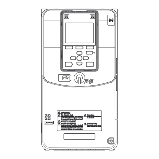
Page 38: Remove And Reattach The Keypad
Insert the keypad connector to its initial position. Put the bottom of the keypad into position first, then carefully push on the top of the keypad until the hook clicks into place. Figure 2.9 Reattach the Keypad SIEPYEUOQ2A01G AC Drive Q2A Technical Manual... -
Page 39: Install The Keypad To A Control Panel Or Another Device
29 (1.14) 22 (0.89) 1 (0.04) 3.6 (0.14) Remove the keypad and put the keypad connector in the holder on the front cover. Note: Insert the end of the keypad connector that has the tab. SIEPYEUOQ2A01G AC Drive Q2A Technical Manual... -
Page 40: Install Inside Control Panel
To attach the keypad inside of the control panel, you must purchase the installation support set, which is sold separately. Contact the manufacturer or your nearest sales representative to order mounting brackets and mounting hardware. SIEPYEUOQ2A01G AC Drive Q2A Technical Manual... - Page 41 Tighten the screws to a tightening torque of 0.49 to 0.73 N∙m (4.34 to 6.46 lb.∙in.). A - Keypad C - M3 screws B - Mounting bracket A Figure 2.16 Attach Keypad to Mounting Bracket SIEPYEUOQ2A01G AC Drive Q2A Technical Manual...
- Page 42 Connect the keypad with the drive using the remote control extension cable. A - Remote control extension D - Keypad B - Communications connector E - Cable connector C - Drive Figure 2.18 Connect the Drive and Keypad with the Remote Control Extension Cable SIEPYEUOQ2A01G AC Drive Q2A Technical Manual...
-
Page 43: External Dimensions Of Keypad
2.6 Install the Keypad to a Control Panel or Another Device ◆ External Dimensions of Keypad Figure 2.19 Exterior and Mounting Dimensions Table 2.4 Exterior Dimensions (mm) 53.8 Minimum bending radius SIEPYEUOQ2A01G AC Drive Q2A Technical Manual... -
Page 44: Removing/Reattaching Covers
50 Vdc. When all indicators are OFF, measure for dangerous voltages to make sure that the drive is safe. If you do work on the drive when it is energized, it will cause serious injury or death from electrical shock. SIEPYEUOQ2A01G AC Drive Q2A Technical Manual... -
Page 45: Remove The Front Cover Of Drive Models 2257 - 2415, 4208 - 4675
Remove the keypad, and keypad connector, then insert the end of the keypad connector that has the tab into the keypad connector holder on the front cover. A - Keypad C - Connector holder B - Keypad connector Figure 2.25 Remove the Terminal Cover, Keypad, and Keypad Connector SIEPYEUOQ2A01G AC Drive Q2A Technical Manual... -
Page 46: Reattach The Front Cover Of Drive Models 2257 - 2415, 4208 - 4675
50 Vdc. When all indicators are OFF, measure for dangerous voltages to make sure that the drive is safe. If you do work on the drive when it is energized, it will cause serious injury or death from electrical shock. SIEPYEUOQ2A01G AC Drive Q2A Technical Manual... - Page 47 • Make sure that you do not pinch wires or signal lines between the wiring cover and the drive before you reattach the cover. • Tighten the screws to a tightening torque of 0.98 N∙m to 1.33 N∙m (8.67 lb.∙in. to 11.77 lb.∙in.). Figure 2.31 Reattach the Terminal Cover SIEPYEUOQ2A01G AC Drive Q2A Technical Manual...
-
Page 48: Change The Drive Enclosure Type
Attach the Conduit Bracket Remove the front cover. Remove the screws that attach the protective covers to the drive. A - Screws that attach the protective cover Figure 2.33 Remove the Screws that Attach the Protective Cover SIEPYEUOQ2A01G AC Drive Q2A Technical Manual... -
Page 49: Attach The Protective Cover Of Drive Models 2110, 4075
A - Mark C - Hooks B - Rear side of top protective cover D - Front of drive Figure 2.36 Attach the Top Protective Cover SIEPYEUOQ2A01G AC Drive Q2A Technical Manual... - Page 50 Tighten the screws to a tightening torque of 0.98 N∙m to 1.33 N∙m (8.67 lb.∙in. to 11.77 lb.∙in.). A - Conduit bracket 2 Figure 2.39 Attach Conduit Bracket 2 Figure 2.40 shows the locations of the screw holes on the bottom of conduit bracket 1. SIEPYEUOQ2A01G AC Drive Q2A Technical Manual...
-
Page 51: Attach The Protective Cover Of Drive Models 2138, 4089 - 4103
Move the cover forward a short distance and tighten the screws to a tightening torque of 0.98 N∙m to 1.33 N∙m (8.67 lb.∙in. to 11.77 lb.∙in.) to attach the cover. A - Hooks C - Temporary placement holes B - Rear side of top protective cover Figure 2.42 Attach the Top Protective Cover SIEPYEUOQ2A01G AC Drive Q2A Technical Manual... - Page 52 Align the screw holes on conduit bracket 2 with the screw holes on conduit bracket 1. Tighten the screws to a tightening torque of 0.98 N∙m to 1.33 N∙m (8.67 lb.∙in. to 11.77 lb.∙in.). SIEPYEUOQ2A01G AC Drive Q2A Technical Manual...
-
Page 53: Attach The Protective Cover Of Drive Models 2169 - 2210, 4140 - 4168
Put the hooks on the back of the top protective cover into the hook holes on the top of the drive. Move the cover forward a short distance and tighten the screws to a tightening torque of 0.98 N∙m to 1.33 N∙m (8.67 lb.∙in. to 11.77 lb.∙in.) to attach the cover. SIEPYEUOQ2A01G AC Drive Q2A Technical Manual... - Page 54 Tighten the screws to a correct tightening torque. • Screw A: 3.92 N∙m to 4.90 N∙m (34.70 lb.∙in. to 43.37 lb.∙in.) • Screw B: 8.83 N∙m to 10.79 N∙m (78.15 lb.∙in. to 95.49 lb.∙in.) SIEPYEUOQ2A01G AC Drive Q2A Technical Manual...
- Page 55 Tighten the screws to a tightening torque of 0.98 N∙m to 1.33 N∙m (8.67 lb.∙in. to 11.77 lb.∙in.). A - Conduit bracket 2 Figure 2.53 Attach Conduit Bracket 2 Figure 2.54 shows the locations of the screw holes on the bottom of conduit bracket 1. SIEPYEUOQ2A01G AC Drive Q2A Technical Manual...
-
Page 56: Attach The Protective Cover Of Drive Models 2257 - 2313, 4208 - 4296
Align the screw holes of the top protective cover with the screw holes on the top of the drive. Tighten the screws to a tightening torque of 0.98 N∙m to 1.33 N∙m (8.67 lb.∙in. to 11.77 lb.∙in.) to attach the cover. Figure 2.56 Attach the Top Protective Cover SIEPYEUOQ2A01G AC Drive Q2A Technical Manual... - Page 57 C - Screws A B - Conduit bracket 1 D - Screws B Figure 2.58 Attach Conduit Bracket 1 Figure 2.59 shows the locations of the screw holes on the bottom of the drive. SIEPYEUOQ2A01G AC Drive Q2A Technical Manual...
-
Page 58: Attach The Protective Cover Of Drive Models 2360, 4371
Align the screw holes of the top protective cover with the screw holes on the top of the drive. Tighten the screws to a tightening torque of 0.98 N∙m to 1.33 N∙m (8.67 lb.∙in. to 11.77 lb.∙in.) to attach the cover. Figure 2.61 Attach the Top Protective Cover SIEPYEUOQ2A01G AC Drive Q2A Technical Manual... - Page 59 C - Screws A B - Conduit bracket 1 D - Screws B Figure 2.63 Attach Conduit Bracket 1 Figure 2.64 shows the locations of the screw holes on the bottom of the drive. SIEPYEUOQ2A01G AC Drive Q2A Technical Manual...
- Page 60 Align the screw holes on conduit bracket 2 with the screw holes on conduit bracket 1. Tighten the screws to a tightening torque of 0.98 N∙m to 1.33 N∙m (8.67 lb.∙in. to 11.77 lb.∙in.). A - Conduit bracket 2 Figure 2.65 Attach Conduit Bracket 2 SIEPYEUOQ2A01G AC Drive Q2A Technical Manual...
-
Page 61: Installation Methods
• The exterior mounting dimensions and installation dimensions for a standard installation are different than the dimensions for an external heatsink installation. • The shaded parts of the panel cut-out dimensions are the gasket dimensions. Make sure that the gasket is not smaller than the specified dimension. SIEPYEUOQ2A01G AC Drive Q2A Technical Manual... - Page 62 (5.43) (1.50) (4.02) (4.02) (0.63) (0.12) (11.10) (0.91) (0.24) (1.02) (0.24) (5.28) (9.17) 2021 2030 2042 2056 23.5 24.5 (7.09) (12.95) (5.28) (2.68) (5.51) (5.51) (0.67) (0.12) (12.52) (0.93) (0.20) (0.97) (0.24) (6.85) (10.63) SIEPYEUOQ2A01G AC Drive Q2A Technical Manual...
- Page 63 (0.51) (16.38) (27.95) 4453 1140 1110 1042 4568 (20.08) (44.88) (10.24) (8.66) (17.72) (15.91) (0.71) (0.47) (7.05) (8.86) (43.70) (1.34) (0.59) (1.34) (0.59) (19.13) (41.02) 4675 The attachment for external heatsink installation is necessary. SIEPYEUOQ2A01G AC Drive Q2A Technical Manual...
- Page 64 2.9 Installation Methods SIEPYEUOQ2A01G AC Drive Q2A Technical Manual...
-
Page 65: Electrical Installation
3.12 Improve the Power Factor ..................108 3.13 Prevent Switching Surge..................109 3.14 Decrease Noise ....................... 110 3.15 Protect the Drive during Failures ............... 112 3.16 Wiring Checklist ..................... 116 3.17 Motor Application Precautions ................118 SIEPYEUOQ2A01G AC Drive Q2A Technical Manual... -
Page 66: Safety Precautions
Do not use the main circuit power supply (Overcurrent Category III) at incorrect voltages. Make sure that the drive rated voltage aligns with the power supply voltage before energizing the drive. Failure to obey can cause death or serious injury. SIEPYEUOQ2A01G AC Drive Q2A Technical Manual... - Page 67 Failure to obey can cause death or serious injury. CAUTION Crush Hazard Do not hold the drive by the front cover or terminal cover. Tighten the screws correctly before moving the drive. Failure to obey can cause minor to moderate injury. SIEPYEUOQ2A01G AC Drive Q2A Technical Manual...
- Page 68 Failure to obey can cause damage to the drive and will void warranty. The manufacturer is not responsible for modifications of the product made by the user. Make sure that all connections are correct after you install the drive and connecting peripheral devices. Failure to obey can cause damage to the drive. SIEPYEUOQ2A01G AC Drive Q2A Technical Manual...
-
Page 69: Standard Connection Diagram
Failure to obey can cause damage to the motor insulation. NOTICE: Do not connect the AC control circuit ground to the drive enclosure. Failure to obey can cause incorrect control circuit operation. SIEPYEUOQ2A01G AC Drive Q2A Technical Manual... - Page 70 The default setting for L5-02 = 1 [Fault@Reset Select = Disable Fault Output]. When you install a DC reactor, you must remove the jumper between terminals +1 and +2. Models 2110 to 2415 and 4060 to 4675 have a DC reactor. SIEPYEUOQ2A01G AC Drive Q2A Technical Manual...
- Page 71 *20 Set DIP switch S2 to “ON” to enable the termination resistor in the last drive in a Modbus network. *21 Use only SOURCE Mode for Safe Disable input. *22 Disconnect the wire jumper between H1 and HC, and H2 and HC to use the Safe Disable input. SIEPYEUOQ2A01G AC Drive Q2A Technical Manual...
-
Page 72: Main Circuit Wiring
B - Connect to the drive ground terminal. E - Use R, S, T for input power supply. C - Ground the motor case. F - Input Protection (Fuses or Circuit Breakers) Figure 3.2 Wiring the Main Circuit and Motor SIEPYEUOQ2A01G AC Drive Q2A Technical Manual... -
Page 73: Configuration Of Main Circuit Terminal Block
Figure 3.3 Configuration of Main Circuit Terminal Block for Drive Models 2004 - 2042, 4002 - 4023 Figure 3.4 Configuration of Main Circuit Terminal Block for Drive Models 2056, 4031, 4038 Figure 3.5 Configuration of Main Circuit Terminal Block for Drive Model 2070, 2082, 4044 SIEPYEUOQ2A01G AC Drive Q2A Technical Manual... - Page 74 Figure 3.6 Configuration of Main Circuit Terminal Block for Drive Model 4060 Figure 3.7 Configuration of Main Circuit Terminal Block for Drive Model 2110, 4075 Figure 3.8 Configuration of Main Circuit Terminal Block for Drive Model 4089 SIEPYEUOQ2A01G AC Drive Q2A Technical Manual...
- Page 75 Figure 3.9 Configuration of Main Circuit Terminal Block for Drive Models 2138, 4103 Figure 3.10 Configuration of Main Circuit Terminal Block for Drive Models 2169, 2211, 4140, 4168 Figure 3.11 Configuration of Main Circuit Terminal Block for Drive Models 2257, 2313, 4208 - 4296 SIEPYEUOQ2A01G AC Drive Q2A Technical Manual...
-
Page 76: Main Circuit Terminal Functions
To connect a commercial power S/L2 Main circuit power supply input supply. T/L3 U/T1 V/T2 Drive output To connect a motor. W/T3 To connect a braking resistor or Braking resistor connection braking resistor unit. SIEPYEUOQ2A01G AC Drive Q2A Technical Manual... -
Page 77: Wire Selection
Wire Gauges and Tightening Torques as Specified by UL Standards on page 201. ◆ Main Circuit Terminal and Motor Wiring This section outlines the various steps, precautions, and checkpoints for wiring the main circuit terminals and motor terminals. SIEPYEUOQ2A01G AC Drive Q2A Technical Manual... - Page 78 NOTICE: To use more than one drive, obey the instructions to ground all drives. Incorrect equipment grounding can cause incorrect operation of drives and equipment. Do not loop the grounding wire when connecting more than one drive. Figure 3.14 Wiring More than One Drive SIEPYEUOQ2A01G AC Drive Q2A Technical Manual...
- Page 79 NOTICE: Do not use the negative DC bus terminal “-” as a ground terminal. This terminal is at high DC voltage potential. Incorrect wiring connections could cause damage to the drive. Figure 3.15 Drive Main Circuit Configuration for Drive Models 2004 to 2082, 4002 to 4044 SIEPYEUOQ2A01G AC Drive Q2A Technical Manual...
- Page 80 3.3 Main Circuit Wiring Figure 3.16 Drive Main Circuit Configuration for Drive Models 2110 to 2138, 4060 to 4168 Figure 3.17 Drive Main Circuit Configuration for Drive Models 2169 to 2313, 4208 to 4250 SIEPYEUOQ2A01G AC Drive Q2A Technical Manual...
- Page 81 3.3 Main Circuit Wiring Figure 3.18 Drive Main Circuit Configuration for Drive Models 2360 to 2415, 4302 to 4675 SIEPYEUOQ2A01G AC Drive Q2A Technical Manual...
-
Page 82: Main Circuit Terminal Block Wiring
• When tightening slotted screws, hold the straight-edge screwdriver perpendicularly to the screw. Do not allow the tip of the screwdriver to shift or protrude from the groove of the screw. Figure 3.20 Tightening Slotted Screws SIEPYEUOQ2A01G AC Drive Q2A Technical Manual... - Page 83 The keypad and front cover must be removed before wiring the main circuit terminal block. Pull the wiring cover forward to remove it from the drive. A - Wiring cover Figure 3.22 Remove the Wiring Cover SIEPYEUOQ2A01G AC Drive Q2A Technical Manual...
- Page 84 Contact the manufacturer or your nearest sales representative for more information. Install the wiring cover to its initial position. Put the cables through the holes cut from the wiring cover. Figure 3.26 Reattach the Wiring Cover SIEPYEUOQ2A01G AC Drive Q2A Technical Manual...
- Page 85 A - Terminal block cover B - Wiring cover Figure 3.27 Remove the Wiring Cover Remove the terminal block nut. A - Nut Figure 3.28 Remove the Terminal Block Nut SIEPYEUOQ2A01G AC Drive Q2A Technical Manual...
- Page 86 • If the recommended gauge for the electrical wires are used, the wiring cover of the main circuit power input terminal and the drive output terminal do not need to be attached. Attach the wiring cover when using the applicable gauge for electrical wires. SIEPYEUOQ2A01G AC Drive Q2A Technical Manual...
- Page 87 Attach the wiring cover and terminal block cover to their initial positions and tighten the screws on the terminal block cover. Figure 3.32 Reattach the Wiring Cover Put the terminal cover back in its initial position. SIEPYEUOQ2A01G AC Drive Q2A Technical Manual...
-
Page 88: Control Circuit Wiring
Wire the drive control circuit as shown in Figure 3.33. Figure 3.33 Control Circuit Connection Diagram To operate the control circuit while the main circuit power supply is OFF, connect a 24 V power supply unit (option). SIEPYEUOQ2A01G AC Drive Q2A Technical Manual... -
Page 89: Control Circuit Terminal Block Functions
MFDI power supply, 24 V (maximum 150 mA) MFDI selection common NOTICE: Do not close the circuit between terminals D24V and D0V. Failure to obey will cause damage to the drive. D24V MFDI power supply +24 Vdc SIEPYEUOQ2A01G AC Drive Q2A Technical Manual... - Page 90 Do not set functions that frequently switch ON/OFF to MFDO (2NO to 4CM) because this will decrease the performance life of the relay contacts. The manufacturer estimates switching life at 200,000 times (assumes 1 MFDO A, resistive load). (Speed agree 1) SIEPYEUOQ2A01G AC Drive Q2A Technical Manual...
-
Page 91: Control Circuit Terminal Configuration
Use the tables in this section to select the correct wires. Use shielded wire for the control circuit terminal block. Use crimp ferrules on the wire ends to make wiring easier and more reliable. SIEPYEUOQ2A01G AC Drive Q2A Technical Manual... -
Page 92: Wiring The Control Circuit Terminal
USB port board. Note: You can temporarily store the USB port board with the temporary placement holes on the drive. The location of the temporary placement holes changes by drive model. SIEPYEUOQ2A01G AC Drive Q2A Technical Manual... - Page 93 NOTICE: Do not use control circuit wiring that is longer than 50 m (164 ft.) to supply the frequency reference with an analog signal from a remote source. Failure to obey could cause unsatisfactory system performance. SIEPYEUOQ2A01G AC Drive Q2A Technical Manual...
-
Page 94: Switches And Jumpers On The Terminal Board
Install the USB port board, front cover, and the keypad to their initial positions. ◆ Switches and Jumpers on the Terminal Board The terminal board has switches to adapt the drive I/Os to the external control signals. Set the switches to select the functions for each terminal. SIEPYEUOQ2A01G AC Drive Q2A Technical Manual... - Page 95 DIP switch S1-2 Selects the input signal type (voltage/current). I (current input) DIP switch S1-3 Selects the input signal type (voltage/current). V (voltage input) DIP switch S4 Selects MFAI or PTC input. AI (analog input) SIEPYEUOQ2A01G AC Drive Q2A Technical Manual...
-
Page 96: Control I/O Connections
10.8 Vdc to 16.5 Vdc. Adjust the load impedance to keep the current at 16 mA or lower. External Power Supply (V) Load Impedance (kΩ) Sinking Current (mA) 10.8 Vdc to 16.5 Vdc 1.0 kΩ or more 16 mA maximum SIEPYEUOQ2A01G AC Drive Q2A Technical Manual... -
Page 97: Set Sinking Mode/Sourcing Mode
External Power 24 V ◆ Set Input Signals for MFAI Terminals AI1 to AI3 Use terminals AI1 to AI3 to input a voltage or a current signal. Figure 3.45 Location of DIP Switch S1 SIEPYEUOQ2A01G AC Drive Q2A Technical Manual... -
Page 98: Set Mfai Terminal Ai3 To Ptc Input
Set the signal type for terminals AO1 and AO2 to voltage or current output. Use jumper switch S5 and H4-07 [AO1 Signal Level Select], H4-08 [AO2 Signal Level Select] to set the signal type. Figure 3.47 Location of Jumper Switch S5 SIEPYEUOQ2A01G AC Drive Q2A Technical Manual... -
Page 99: Switch On Termination Resistor For Modbus Communications
RS-485 interface. Figure 3.48 Location of DIP Switch S2 Table 3.16 Modbus Communications Termination Resistor Setting DIP Switch S2 Description The built-in termination resistor is ON. OFF (Default) The built-in termination resistor is OFF. SIEPYEUOQ2A01G AC Drive Q2A Technical Manual... -
Page 100: Connect The Drive To A Pc
PC, you can use Q2Edit software to monitor drive performance and manage parameter settings. A - USB 2.0, type A - mini-B cable C - Type-A connector B - Mini-B type connector D - PC Figure 3.49 Connect to a PC (USB) SIEPYEUOQ2A01G AC Drive Q2A Technical Manual... -
Page 101: External Interlock
This is an example of how two drives that run one application use the Drive Ready and Fault output signals to interlock with the controller. Terminal Output Signal Parameter Settings for Output Signal 1NO, 1NC, 1CM Fault 2NO, 2CM Drive Ready H2-01 = 1 [Drive Ready] Figure 3.50 Interlock Circuit Example SIEPYEUOQ2A01G AC Drive Q2A Technical Manual... -
Page 102: Braking Resistor Installation
H2-01 to H2-03 = 4C [Multi-Function Digital Output 1 to Multi-Function Digital Output 3 = BrkRes Fault]. Use a sequence that uses MFDO to de-energize the drive. ◆ Install a Braking Resistor Unit: LKEB-Type Connect the braking resistor unit as shown. SIEPYEUOQ2A01G AC Drive Q2A Technical Manual... -
Page 103: Install A Braking Unit Connection: Cdbr-Type
To install a CDBR-type braking unit to the drive models 2004 to 2138 and 4002 to 4168 that have a built-in braking transistor, connect drive terminal B1 to terminal + on the braking unit. ◆ Connect Braking Units in Parallel To connect two or more braking units in parallel, wire and select connections as shown. SIEPYEUOQ2A01G AC Drive Q2A Technical Manual... -
Page 104: Dynamic Braking Option Overload Protection
WARNING! Fire Hazard. When you use a braking unit, use a thermal relay on the braking resistors and set a fault contact output for the braking resistor unit to disconnect drive main power through an input contactor. Incorrect braking circuit protection can overheat the resistors and cause death or serious injury by fire. SIEPYEUOQ2A01G AC Drive Q2A Technical Manual... -
Page 105: Drive Wiring Protection
To prevent damage and injury to personnel and drives, use a high-frequency RCM/RCD that is rated for AC and DC power supplies. Note: The manufacturer recommends these RCM/RCDs, which are designed to operate with high frequencies. • Mitsubishi Electric Corporation; NV series • Schneider Electric; NS series SIEPYEUOQ2A01G AC Drive Q2A Technical Manual... -
Page 106: Dynamic Braking Option, Motor Protection
• Operating more than one motor from one drive To disable the overload protection function of the electronic thermal protector of the drive, set L1-01 = 0 [Motor Cool Type for OL1 Calc = Disabled]. SIEPYEUOQ2A01G AC Drive Q2A Technical Manual... - Page 107 WARNING! Fire Hazard. Make sure that a secondary problem is not the cause of the overload before you increase the detection level of the thermal relay. Verify local ordinances for electrical wiring, then adjust electrothermal settings. Incorrect wiring can cause death or serious injury from fire. SIEPYEUOQ2A01G AC Drive Q2A Technical Manual...
-
Page 108: Improve The Power Factor
When you install a DC link choke, remove the jumper between terminals +1 and +2. If you will not use a DC link choke, do not remove the jumper. A - Power supply C - Drive B - MCCB D - DC reactor Figure 3.58 DC Reactor Connection Example SIEPYEUOQ2A01G AC Drive Q2A Technical Manual... -
Page 109: Prevent Switching Surge
• Electromagnetic relays • Magnetic valves • Solenoids • Magnetic brakes. Always use a surge protective device or diode with inductive loads. Note: Do not connect a surge protective device to the drive output side. SIEPYEUOQ2A01G AC Drive Q2A Technical Manual... -
Page 110: Decrease Noise
In addition to installing a noise filter, you can also run all wiring through a grounded metal conduit to decrease inductive noise occurring at the output side. Put the cables a minimum of 30 cm (11.8 in.) away from the signal line to prevent induced noise. Ground the cables to metal conduits. SIEPYEUOQ2A01G AC Drive Q2A Technical Manual... - Page 111 Keep the cable between the drive and motor as short as possible. A - Steel box E - Noise filter B - Power supply F - Shielded motor cable C - Noise filter G - Motor D - Drive Figure 3.62 Decrease Radio Frequency Interference SIEPYEUOQ2A01G AC Drive Q2A Technical Manual...
-
Page 112: Protect The Drive During Failures
The built-in short circuit protection of the drive does not provide branch circuit protection. The user must provide branch circuit protection as specified by the National Electric Code (NEC), the Canadian Electric Code, Part I (CEC), and local codes. SIEPYEUOQ2A01G AC Drive Q2A Technical Manual... -
Page 113: Branch Circuit Protection For 400 V Class (Nd)
7.5 (10) 7.5 (10) 21.2 FWH-80B 4023 11 (15) 11 (15) 30.6 FWH-90B 4031 15 (20) 15 (20) 41.3 FWH-150B 4038 18.5 (25) 18.5 (25) 50.5 FWH-200B 4044 22 (30) 22 (30) 59.7 FWH-200B SIEPYEUOQ2A01G AC Drive Q2A Technical Manual... -
Page 114: Branch Circuit Protection For 400 V Class (Hd)
FWH-250A 4089 37 (50) 37 (50) 71.5 FWH-275A 4103 45 (60) 45 (60) 86.5 FWH-275A 4140 55 (75) 55 (75) FWH-300A FWH-325A 4168 75 (100) 75 (100) FWH-400A 4208 90 (125) 90 (125) FWH-500A SIEPYEUOQ2A01G AC Drive Q2A Technical Manual... - Page 115 FWH-1000A 4453 220 (300) 260 (350) FWH-1200A 4568 250 (335) 300 (400) FWH-1200A FWH-1400A 4675 315 (400) 335 (450) FWH-1600A A fuse with a large rated current for applications with repeated loads is recommended. SIEPYEUOQ2A01G AC Drive Q2A Technical Manual...
-
Page 116: Wiring Checklist
Tighten the control circuit terminal screws of the drive to their specified torques. Pick up all wire clippings. Make sure that none of the wires on the terminal block touch other terminals or connections. Isolate control circuit wiring from main circuit wiring. SIEPYEUOQ2A01G AC Drive Q2A Technical Manual... - Page 117 3.16 Wiring Checklist Checked Item to Check Make sure that control circuit wiring is not longer than 50 m (164 ft.). Make sure that Safe Disable input wiring is not longer than 30 m (98 ft.). SIEPYEUOQ2A01G AC Drive Q2A Technical Manual...
-
Page 118: Motor Application Precautions
• Subsynchronous resonance Subsynchronous resonance can occur with long motor shafts and in applications such as turbines, blowers, and fans with high inertia loads. Use Closed Loop Vector Control when these applications have subsynchronous resonance problems. SIEPYEUOQ2A01G AC Drive Q2A Technical Manual... -
Page 119: Precautions For Pm Motors
You must test the motor and the drive together for explosion-proof certification. You must also test existing installations of explosion-proof motors. The drive is not designed for explosion-proof areas. Install the drive in a safe location. SIEPYEUOQ2A01G AC Drive Q2A Technical Manual... -
Page 120: Notes On The Power Transmission Mechanism
If you operate at frequencies higher than the rated frequency, it can cause problems with the power transmission mechanism. These problems include audible noise, decreased service life, and decreased durability. SIEPYEUOQ2A01G AC Drive Q2A Technical Manual... -
Page 121: Startup Procedure And Test Run
User Interface Elements ..................123 Start-up Procedures ....................126 Items to Check before Starting Up the Drive...........130 Keypad Operation ....................131 Auto-Tuning ......................147 Test Run ........................156 Fine Tuning during Test Runs (Adjust the Control Function).....158 Test Run Checklist ....................164 SIEPYEUOQ2A01G AC Drive Q2A Technical Manual... -
Page 122: Safety Precautions
Failure to obey could cause death or serious injury. Crush Hazard In hoist applications, use the applicable safety precautions to prevent the load from falling. Failure to obey can cause death or serious injury from falling loads. SIEPYEUOQ2A01G AC Drive Q2A Technical Manual... -
Page 123: User Interface Elements
Selection of Function = Disabled] to disable switching from REMOTE to LOCAL by • The drive will not switch between LOCAL and REMOTE when it is receiving a Run command from an external source. SIEPYEUOQ2A01G AC Drive Q2A Technical Manual... -
Page 124: Operator Display
In Q2pack operation, FWD or REV flash. The screen will show Rdy when the drive is ready for operation or when the drive is running. Ready Shows the name of the current mode or screen. Mode display area SIEPYEUOQ2A01G AC Drive Q2A Technical Manual... -
Page 125: Keypad Mode And Menu Displays
Programming Mode OPTIONS TERMINALS Changes terminals settings. Changes protection settings. PROTECTION Changes settings for special applications. SPECIAL Changes keypad settings. KEYPAD Q2PACK PARAMETERS Changes parameters of Q2Pack software. Changes joints of Q2Pack software. Q2PACK JOINTS SIEPYEUOQ2A01G AC Drive Q2A Technical Manual... -
Page 126: Start-Up Procedures
Flowchart A shows a basic start-up sequence to connect and run a motor with a minimum of setting changes. Settings can change when the application changes. Use the drive default parameter settings for basic applications where high precision is not necessary. Figure 4.3 Basic Steps before Startup SIEPYEUOQ2A01G AC Drive Q2A Technical Manual... -
Page 127: Sub-Chart A-1: Induction Motor Auto-Tuning And Test Run Procedure
In ASR Tuning, the drive will automatically tune Feed Forward control and KEB Ride-Thru 2 parameters. ◆ Sub-Chart A-2: PM Motor Auto-Tuning and Test Run Procedure Sub-Chart A-2 gives the basic steps to start up the drive for a PM motor. SIEPYEUOQ2A01G AC Drive Q2A Technical Manual... - Page 128 WARNING! Crash Hazard. Test the system to make sure that the drive operates safely after you wire the drive and set parameters. Failure to obey can cause injury or damage to equipment. Figure 4.5 PM Motor Auto-Tuning and Test Run Procedure SIEPYEUOQ2A01G AC Drive Q2A Technical Manual...
-
Page 129: Sub-Chart A-3: Ez Open Loop Vector Control Test Run Procedure
Sub-Chart A-3: EZ Open Loop Vector Control Test Run Procedure Subchart A-3 gives the setup procedure to run a PM motor in EZ Open Loop Vector Control. Figure 4.6 Procedure for Test Run of EZ Open Loop Vector Control Method SIEPYEUOQ2A01G AC Drive Q2A Technical Manual... -
Page 130: Items To Check Before Starting Up The Drive
If the screen shows a different screen, do these steps to show the fault content again: Detects a Fault Push from the HOME screen. Push (Home) from a different screen than the HOME screen. SIEPYEUOQ2A01G AC Drive Q2A Technical Manual... -
Page 131: Keypad Operation
Note: The HOME screen must show U1-01 [Frequency Reference]. You can activate the LO/RE key only in the HOME screen. ■ Show the Main Menu Push to show the main menu. SIEPYEUOQ2A01G AC Drive Q2A Technical Manual... -
Page 132: Show The Standard Monitor
Enter the three digits in “x-xx” part of monitor Ux-xx to identify which monitor to output. For example, to show monitor U1-05, set it to “105” as shown in this figure. Push SIEPYEUOQ2A01G AC Drive Q2A Technical Manual... -
Page 133: Show Custom Monitors
Enter the three digits in “x-xx” part of monitor Ux-xx to identify which monitor to output. For example, to show monitor U1-01 [Frequency Reference], set it to "101" as shown in this figure. Push The configuration procedure is complete. SIEPYEUOQ2A01G AC Drive Q2A Technical Manual... -
Page 134: Show Monitors As Bar Graphs
• [ ] appears in the upper right hand corner of the screen when in HOME mode. • If [ ] is not shown on , push ( ) to show [ ] on SIEPYEUOQ2A01G AC Drive Q2A Technical Manual... -
Page 135: Set Monitoring Items To Be Shown As A Trend Plot
When the U parameters are on the display as "Ux-xx", the three digits in "x-xx" identify which monitor to output. For example, to show monitor U1-01 [Frequency Reference], set it to "101" as shown in this figure. Push SIEPYEUOQ2A01G AC Drive Q2A Technical Manual... - Page 136 [Trend Plot], then push Push to select [Trend Plot Time Scale Setting], then push Push to select the specified digit, then push to select the correct number. Push to keep the changes. The configuration procedure is complete. SIEPYEUOQ2A01G AC Drive Q2A Technical Manual...
-
Page 137: Show Monitor Items As A Trend Plot
[Min/Max] to show the minimum value or the maximum value on the display. Push to keep the changes. Continue to change parameters, then push [ ] to go back to the home screen after you change all the applicable parameters. SIEPYEUOQ2A01G AC Drive Q2A Technical Manual... -
Page 138: Examine Manual Setup Parameters
Push to select [Bck (Drive → OPE)], then push Push to select a memory location, then push The keypad shows “End” when the backup procedure completes successfully. SIEPYEUOQ2A01G AC Drive Q2A Technical Manual... -
Page 139: Write Backed-Up Parameters To The Drive
] on Push ( ). Push to select [Configuration], then push Push to select [Parameter Backup/Restore], then push Push to select the item to verify, then push Push to select [Verify (Check)], then push SIEPYEUOQ2A01G AC Drive Q2A Technical Manual... -
Page 140: Delete Parameters Backed Up To The Keypad
• [ ] appears in the upper right hand corner of the screen when in HOME mode. • If [ ] is not shown on , push ( ) to show [ ] on SIEPYEUOQ2A01G AC Drive Q2A Technical Manual... -
Page 141: Show Fault History
] appears in the upper right hand corner of the screen when in HOME mode. • If [ ] is not shown on , push ( ) to show [ ] on Push ( ). SIEPYEUOQ2A01G AC Drive Q2A Technical Manual... -
Page 142: Set The Keypad Language Display
[Language Selection], then push Push to select the language, then push The procedure to set the keypad language is complete. ◆ Set the Date and Time This procedure shows how to set the date and time. SIEPYEUOQ2A01G AC Drive Q2A Technical Manual... -
Page 143: Set Parameters Using The Q2 Wizard
The procedure for setting the date and time is complete. ◆ Set Parameters Using the Q2 Wizard The Q2 Wizard lets users follow simple messages on the keypad to set these basic parameters: • Frequency reference source • Input signal level •... -
Page 144: Start Data Logging
Push to select the monitor number to be logged, then push The setting procedure is complete. ■ Set the Sampling Time This procedure shows how to set the sampling time for data logging. SIEPYEUOQ2A01G AC Drive Q2A Technical Manual... -
Page 145: Set Backlight To Automatically Turn Off
] is not shown on , push ( ) to show [ ] on Push ( ). Push to select [Configuration], then push Push to select [Drive Information], then push The keypad will show the drive information. SIEPYEUOQ2A01G AC Drive Q2A Technical Manual... -
Page 146: Write Automatically Backed-Up Parameters To The Drive
The drive will ask to restore the parameters. Push to select [Yes] and then push Push to select [Yes] and then push to confirm the restore process. The keypad will show the “End” message when the write process is complete. SIEPYEUOQ2A01G AC Drive Q2A Technical Manual... -
Page 147: Auto-Tuning
A terminal to which H2-xx = 3 [H2-xx: MFDO Function Select = Fault] is assigned functions the same as during usual operation. In software versions PRG: 23011 and older, the output keeps the status at start of Auto-Tuning. SIEPYEUOQ2A01G AC Drive Q2A Technical Manual... - Page 148 3. After the motor stops, check the E2-02 and E2-03 values on the “Modified Parameters/Fault Log” screen or the “Parameters” screen again. 4. Make sure that the input data is correct. When the settings in E2-02 and E2-03 are different than in step 1, the drive set the values automatically. SIEPYEUOQ2A01G AC Drive Q2A Technical Manual...
-
Page 149: Auto-Tuning For Induction Motors
This section gives information about Auto-Tuning for induction motors. Set these parameters for Auto-Tuning: • Motor parameters E1-xx [E1: V/F PARAMETER MOTOR 1], E2-xx [E2: MOTOR 1 PARAMETERS] (E3-xx [E3: V/F PARAMETER MOTOR 2], E4-xx [E4: MOTOR 2 PARAMETERS] for motor 2) SIEPYEUOQ2A01G AC Drive Q2A Technical Manual... - Page 150 0 Hz is displayed as the initial value. If you do not know the Motor Rated Slip Frequency, keep the setting at 0 Hz. Input this value when A1-02 = 0 or 1 [Control Method = V/f Control or PG V/f Control]. SIEPYEUOQ2A01G AC Drive Q2A Technical Manual...
-
Page 151: Auto-Tuning For Pm Motors
T2-05 [PMMot Rated Voltage] × × × × T2-06 [PMMot Rated Current] × × × × T2-07 [PMMot Base Frequency] × × T2-08 [PMMot Poles Number] × × × × T2-09 [PMMot Base Speed] × × SIEPYEUOQ2A01G AC Drive Q2A Technical Manual... -
Page 152: Ez Tuning
Changes when the value set in T2-13 [KE Unit Selection] changes. ◆ EZ Tuning This section gives information about the Auto-Tuning mode for EZ Open Loop Vector Control. Auto-Tuning will set the E9-xx [E9: SIMPLE VECTOR SETTINGS] parameters. SIEPYEUOQ2A01G AC Drive Q2A Technical Manual... -
Page 153: Control Tuning
× × • When MFDI H1-xx = 42 [H1-xx: MFDI Function Select = KEB Thru2 NC]. To let the set response frequency ASR Tuning (including Inertia Tuning) × × automatically adjust the ASR gain. SIEPYEUOQ2A01G AC Drive Q2A Technical Manual... - Page 154 C1-02 [Decel Time 1] × C1-08 [Decel Time 4] × C1-09 [Fast Stop Time] × C5-01 [ASR PGain 1] × C5-17 [Motor Inertia] × × C5-37 [M2 Inertia] × × C5-18 [Inertia Ratio of Load] × × SIEPYEUOQ2A01G AC Drive Q2A Technical Manual...
- Page 155 L2-06 [KEB Decel Time]. If the Fast Stop time must not change, do not do KEB Tuning. When L2-29 = 2, 3, or 4 [KEB Method = Single KEB2 Ride-Thru, System KEB1 Ride-Thru, or System KEB2 Ride-Thru], the drive will automatically adjust L2-06 [KEB Decel Time]. SIEPYEUOQ2A01G AC Drive Q2A Technical Manual...
-
Page 156: Test Run
Test the operation without a load, then connect the motor and machine to do a test run. ■ Precautions before Operation Before rotating the motor, check these items: • Check for safety issues near the drive, motor, and machine. SIEPYEUOQ2A01G AC Drive Q2A Technical Manual... -
Page 157: Do An Actual-Load Test Run
Change the frequency reference and direction of motor rotation, and make sure that there are no unusual sounds or vibrations. If there are hunting or oscillation errors caused by control function, adjust the settings to stop the errors. SIEPYEUOQ2A01G AC Drive Q2A Technical Manual... -
Page 158: Fine Tuning During Test Runs (Adjust The Control Function)
In Open Loop Vector Control, keep C4-01 [Trq Comp Gain] at its default setting (1.00). Do not adjust it. If you cannot get speed precision during regeneration in Open Loop Vector Control, set C3-04 = 1 [Slip Comp@Regen = Enable>6 Hz]. SIEPYEUOQ2A01G AC Drive Q2A Technical Manual... - Page 159 Default value changes when A1-02 [Control Method] and E1-03 [V/f Pattern Selection] values change. Default value changes when Drive KVA Selection and ND/HD Duty Selection values change. Recommended settings are for 200 V class drives. Multiply the voltage by 2 for 400 V class drives. SIEPYEUOQ2A01G AC Drive Q2A Technical Manual...
-
Page 160: Closed Loop Vector Control Method
Refer to the section on C5: ASR - SPEED REGULATION parameters for more information about speed control (ASR). The best values for a no-load operation are different than the best values for actual loading operation. SIEPYEUOQ2A01G AC Drive Q2A Technical Manual... -
Page 161: Fine-Tuning Open Loop Vector Control For Pm Motors
Set to a value lower than the actual input voltage. • 400.0 V Level] speed and maximum output voltage. Default value changes when E5-01 [PM Mot Code Selection] and o2-04 [Drive KVA Selection] values change. SIEPYEUOQ2A01G AC Drive Q2A Technical Manual... -
Page 162: Advanced Open Loop Vector Control Method For Pm
C5-07 [ASR Gain Switch Change the ASR proportional gain and ASR integral 0.0% to maximum rotation proportional gain or integral time for 0.0% Frequency] time to conform to the output frequency. speed low speed or high speed. SIEPYEUOQ2A01G AC Drive Q2A Technical Manual... - Page 163 L7-01 [FW Torque Limit] to Increase in increments of Motor stalls. Increase the setting value. 200% L7-04 [RV Reg. TrqLimit] 10%. The best values for a no-load operation are different than the best values for actual loading operation. SIEPYEUOQ2A01G AC Drive Q2A Technical Manual...
-
Page 164: Test Run Checklist
Table 4.31 PM Closed Loop Vector Control [A1-02 = 7] Check Description Set E5: PM MOTOR SETTINGS parameters. Set ASR PGain 1 and ASR ITime 1. Set Enc1 Pulse Count (PPR) and Enc1 Rotat Selection. Set Enc ZPulse Offset. SIEPYEUOQ2A01G AC Drive Q2A Technical Manual... - Page 165 Bias adjustment: Set the maximum voltage/current values, then adjust the analog input bias until the frequency reference reaches the necessary minimum value. (For terminal AI1 input: H3-04, for terminal AI2 input: H3-12, for terminal AI3 input: H3-08) SIEPYEUOQ2A01G AC Drive Q2A Technical Manual...
- Page 166 4.9 Test Run Checklist SIEPYEUOQ2A01G AC Drive Q2A Technical Manual...
-
Page 167: Standards Compliance
This chapter gives information about how to make the machines and devices that use this product comply with European standards and UL standards. Safety Precautions....................168 European Standards....................170 UL Standards......................199 China RoHS Compliance ..................222 对应中国RoHS指令....................223 Safe Disable Input ....................224 SIEPYEUOQ2A01G AC Drive Q2A Technical Manual... -
Page 168: Safety Precautions
Do not put flammable or combustible materials on top of the drive and do not install the drive near flammable or combustible materials. Attach the drive to metal or other noncombustible material. Failure to obey can cause death or serious injury. SIEPYEUOQ2A01G AC Drive Q2A Technical Manual... - Page 169 Failure to obey can cause damage to the drive and will void warranty. The manufacturer is not responsible for modifications of the product made by the user. Make sure that all connections are correct after you install the drive and connecting peripheral devices. Failure to obey can cause damage to the drive. SIEPYEUOQ2A01G AC Drive Q2A Technical Manual...
-
Page 170: European Standards
• IEC 62061:2005/A2:2015 (SILCL3) • EN 62061:2005/A2:2015 (SILCL3) 2006/42/EC • IEC/EN 61800-5-2:2016 The customer must display the CE Mark on the final device containing this product. Customers must verify that the final device complies with EU standards. SIEPYEUOQ2A01G AC Drive Q2A Technical Manual... -
Page 171: Eu Declaration Of Conformity
5.2 European Standards ◆ EU Declaration of Conformity SIEPYEUOQ2A01G AC Drive Q2A Technical Manual... - Page 172 5.2 European Standards SIEPYEUOQ2A01G AC Drive Q2A Technical Manual...
- Page 173 5.2 European Standards SIEPYEUOQ2A01G AC Drive Q2A Technical Manual...
- Page 174 5.2 European Standards SIEPYEUOQ2A01G AC Drive Q2A Technical Manual...
- Page 175 5.2 European Standards SIEPYEUOQ2A01G AC Drive Q2A Technical Manual...
- Page 176 5.2 European Standards SIEPYEUOQ2A01G AC Drive Q2A Technical Manual...
-
Page 177: Ce Low Voltage Directive Compliance
When installing IP20 enclosure drives, use an enclosure that does not let unwanted material enter the drive from above or below. ■ Wiring Diagram Example of a drive that is wired to comply with the CE Low Voltage Directive. SIEPYEUOQ2A01G AC Drive Q2A Technical Manual... - Page 178 WARNING! Electrical Shock Hazard. Only connect peripheral options, for example a DC reactor or braking resistor, to terminals +1, +2, +3, -, B1, and B2. Failure to obey can cause death or serious injury. SIEPYEUOQ2A01G AC Drive Q2A Technical Manual...
- Page 179 2.3 - 2.5 2018 -, +1, +2 (2.5 - 16) (19.8 - 22) 2.5 - 4 1.5 - 1.7 B1, B2 (2.5 - 4) (13.5 - 15) 2.5 - 10 1.2 - 1.5 (10.6 - 13.3) SIEPYEUOQ2A01G AC Drive Q2A Technical Manual...
- Page 180 5 - 5.5 2070 -, +1, +2 (35 - 50) (45 - 49) 2.5 - 10 1.5 - 1.7 B1, B2 (2.5 - 10) (13.5 - 15) 16 - 25 5.4 - 6.0 (47.8 - 53.1) SIEPYEUOQ2A01G AC Drive Q2A Technical Manual...
- Page 181 8 - 9 *5 *6 2211 -, -, +1, +1 (50) (71 - 80) 25 - 70 8 - 9 (50 - 70) (71 - 80) 25 - 50 9.0 - 11 (79.7 - 97.4) SIEPYEUOQ2A01G AC Drive Q2A Technical Manual...
- Page 182 Install an RCM/RCD with this wire gauge to maintain compliance with IEC/EN 61800-5-1:2007. Terminals - and +1 have two screws. The Recommended Gauge is the wire gauge for one terminal. A junction terminal is necessary to connect a braking unit (CDBR-series) to terminals - and +3. SIEPYEUOQ2A01G AC Drive Q2A Technical Manual...
- Page 183 Slotted (-) (2.5 - 16) (19.8 - 22) 2.5 - 4 1.5 - 1.7 B1, B2 Slotted (-) (2.5 - 4) (13.5 - 15) 2.5 - 10 1.2 - 1.5 Phillips/slotted combo (10.6 - 13.3) SIEPYEUOQ2A01G AC Drive Q2A Technical Manual...
- Page 184 (10 - 35) (WAF: 5 mm) (45 - 49) 2.5 - 10 1.5 - 1.7 B1, B2 Slotted (-) (2.5 - 10) (13.5 - 15) 6 - 16 5.4 - 6.0 Phillips/slotted combo (47.8 - 53.1) SIEPYEUOQ2A01G AC Drive Q2A Technical Manual...
- Page 185 (WAF: 6 mm) (89 - 107) 6 - 35 3 - 3.5 B1, B2 Minus (-) (6 - 35) (27 - 31) 16 - 25 5.4 - 6.0 Hex bolt (+) (47.8 - 53.1) SIEPYEUOQ2A01G AC Drive Q2A Technical Manual...
- Page 186 Hex self-locking nut (120 × 2P) (177) 25 - 70 × 2P 70 × 2P Hex self-locking nut (70 × 2P) (177) 95 - 240 18 - 23 Hex bolt (slotted) (159 - 204) SIEPYEUOQ2A01G AC Drive Q2A Technical Manual...
- Page 187 Terminals - and +1 have two screws. The Recommended Gauge is the wire gauge for one terminal. A junction terminal is necessary to connect a braking resistor unit (LKEB-series) to terminals B1 and B2. SIEPYEUOQ2A01G AC Drive Q2A Technical Manual...
- Page 188 CE Standards Compliance for DC Power Supply Input To comply with CE Standards, install a fuse for the DC power supply input. Example for a DC power supply that has two drives connected in parallel. SIEPYEUOQ2A01G AC Drive Q2A Technical Manual...
- Page 189 A fuse with a large rated current for applications with repeated loads is recommended. Table 5.5 Recommended Fuse (Three-Phase 400 V Class) Fuse Manufacturer: Bussmann Drive Model Model Quantity 4002 FWH-50B 4004 FWH-50B 4005 FWH-50B SIEPYEUOQ2A01G AC Drive Q2A Technical Manual...
-
Page 190: Emc Directive
Install drives with this procedure to comply with the EMC Directive when the drive is a single unit or installed in a larger device. Install the drive on a grounded metal plate. Wire the drive and motor. SIEPYEUOQ2A01G AC Drive Q2A Technical Manual... - Page 191 Make sure that the protective ground wire complies with technical specifications and local safety standards. A - Braided shield cable C - Cable clamp (conductive) B - Metal plate Figure 5.5 Ground the shield SIEPYEUOQ2A01G AC Drive Q2A Technical Manual...
- Page 192 Enable the Internal EMC Filter Move the screw or screws to turn ON and OFF (enable and disable) the EMC filter. SIEPYEUOQ2A01G AC Drive Q2A Technical Manual...
- Page 193 Table 5.6 Asymmetric Grounding Type of Grounding Diagram Grounded at the corner of the delta connection Grounded at the middle of the side Single-phase, grounded at the end point Three-phase variable transformer without solidly grounded neutral SIEPYEUOQ2A01G AC Drive Q2A Technical Manual...
- Page 194 A - SW (ON) B - Screw (OFF) Figure 5.9 EMC Filter Switch Location (2056, 4031, 4038) A - SW (ON) B - Screw (OFF) Figure 5.10 EMC Filter Switch Location (2070, 2082, 4044, 4060) SIEPYEUOQ2A01G AC Drive Q2A Technical Manual...
- Page 195 B - Screw (OFF) Figure 5.12 EMC Filter Switch Location (2257 - 2313, 4208 - 4296) A - SW (ON) B - Screw (OFF) Figure 5.13 EMC Filter Switch Location ( 2360, 2415, 4371, 4389) SIEPYEUOQ2A01G AC Drive Q2A Technical Manual...
- Page 196 • Keep the grounding wire as short as possible. Use a cable clamp to ground the motor cable to the metal plate. Note: Make sure that the protective ground wire complies with technical specifications and local safety standards. SIEPYEUOQ2A01G AC Drive Q2A Technical Manual...
- Page 197 C - Metal plate H - Cable clamp D - Drive I - Grounding wire E - Ground the shield. J - EMC noise filter Figure 5.17 EMC Noise Filter and Drive Installation Procedure SIEPYEUOQ2A01G AC Drive Q2A Technical Manual...
- Page 198 Table 5.9 DC Reactors for Harmonic Suppression for 400 V Class (Manufacturer: Yaskawa Electric) Drive Model DC Reactor Model DC Reactor Rating 4002 UZDA-B 3.2 A, 28 mH 4004 UZDA-B 3.2 A, 28 mH SIEPYEUOQ2A01G AC Drive Q2A Technical Manual...
-
Page 199: Ul Standards
To select the correct wire gauge, refer to Wire Gauges and Tightening Torques as Specified by UL Standards on page 201. ■ Notes on Wiring the Main Circuit Terminal Block Read these notes before you wire the main circuit terminal block. SIEPYEUOQ2A01G AC Drive Q2A Technical Manual... - Page 200 • Remove the correct section of the wiring cover to make wiring easier. • Do not let strain on the wiring cause damage. Use a strain relief near the wiring to release the tension. A - Strain relief Figure 5.21 Strain Relief Example SIEPYEUOQ2A01G AC Drive Q2A Technical Manual...
- Page 201 (19.8 - 22) 14 - 10 14 - 10 1.5 - 1.7 B1, B2 (2.5 - 6.0) (2.5 - 6.0) (13.5 - 15) 14 - 8 1.2 - 1.5 (2.5 - 10) (10.6 - 13.3) SIEPYEUOQ2A01G AC Drive Q2A Technical Manual...
- Page 202 (19.8 - 22) 14 - 10 14 - 10 1.5 - 1.7 B1, B2 (2.5 - 6.0) (2.5 - 6.0) (13.5 - 15) 10 - 8 2.0 - 2.5 (6.0 - 10) (17.7 - 22.1) SIEPYEUOQ2A01G AC Drive Q2A Technical Manual...
- Page 203 (89 - 107) 14 - 4 10 - 4 3 - 3.5 B1, B2 (2.5 - 25) (6.0 - 25) (27 - 31) 6 - 4 5.4 - 6.0 (16 - 25) (47.8 - 53.1) SIEPYEUOQ2A01G AC Drive Q2A Technical Manual...
- Page 204 (95 × 2P) (177) 4 - 1/0 × 2P 1/0 × 2P 1/0 × 2P (25 - 50 × 2P) (50 × 2P) (177) 2 - 350 18 - 23 (35 - 150) (159 - 204) SIEPYEUOQ2A01G AC Drive Q2A Technical Manual...
- Page 205 Slotted (-) (14 - 3) (19.8 - 22) 14 - 10 1.5 - 1.7 B1, B2 Slotted (-) (14 - 10) (13.5 - 15) 14 - 8 1.2 - 1.5 Phillips/slotted combo (10.6 - 13.3) SIEPYEUOQ2A01G AC Drive Q2A Technical Manual...
- Page 206 Slotted (-) (14 - 3) (19.8 - 22) 14 - 10 1.5 - 1.7 B1, B2 Slotted (-) (14 - 10) (13.5 - 15) 14 - 8 2.0 - 2.5 Phillips/slotted combo (17.7 - 22.1) SIEPYEUOQ2A01G AC Drive Q2A Technical Manual...
- Page 207 Slotted (-) (10 - 3) (19.8 - 22) 14 - 8 1.5 - 1.7 B1, B2 Slotted (-) (14 - 8) (13.5 - 15) 8 - 4 5.4 - 6.0 Phillips/slotted combo (47.8 - 53.1) SIEPYEUOQ2A01G AC Drive Q2A Technical Manual...
- Page 208 (71 - 80) 4 - 2/0 Hex socket cap 8 - 9 B1, B2 (1 - 2/0) (WAF: 6 mm) (71 - 80) 4 - 1/0 9.0 - 11 Hex bolt (slotted) (79.7 - 97.4) SIEPYEUOQ2A01G AC Drive Q2A Technical Manual...
- Page 209 400 × 2P Hex self-locking nut (300 - 400 × 2P) (310) 1 - 4/0 × 2P 4/0 × 2P Hex self-locking nut (310) 1 - 350 32 - 40 Hex bolt (slotted) (283 - 354) SIEPYEUOQ2A01G AC Drive Q2A Technical Manual...
- Page 210 Terminal Screw Size Cap Model Model S/L2 V/T2 -, +1 Tool Model Die Jaw T/L3 W/T3 2004 - 2021 R5.5-4 YA-4 AD-900 TP-005 2030, 2042 R8-5 YA-4 AD-901 TP-008 2056 R14-6 YA-4 AD-902 TP-014 SIEPYEUOQ2A01G AC Drive Q2A Technical Manual...
- Page 211 TP-005 4031 R8-6 YA-4 AD-901 TP-008 4038 R14-6 YA-4 AD-902 TP-014 4044, 4060 R14-6 YA-4 AD-902 TP-014 4075 R14-6 YA-4 AD-902 TP-014 4089, 4103 R22-6 YA-5 AD-953 TP-022 4140, 4168 R22-8 YA-5 AD-953 TP-022 SIEPYEUOQ2A01G AC Drive Q2A Technical Manual...
- Page 212 300 × 4P TD-323, TD- 80-12 TP-080 TD-324, TD- 4/0 × 4P R100-12 TP-100 YF-1 4675 YET-300-1 TD-325, TD- 300 × 4P 300 × 4P R150-12 TP-150 TD-327, TD- 400 × 4P R200-12 TP-200 SIEPYEUOQ2A01G AC Drive Q2A Technical Manual...
- Page 213 Rated Current Drive Model kW (HP) Manufacturer: EATON/Bussmann 2004 0.55 (0.5) FWH-45B 2006 0.75 (1) FWH-45B 2010 1.5 (2) FWH-45B 2012 2.2 (3) 12.7 FWH-50B 2018 3 (4) FWH-80B 2021 3.7 (5) 20.7 FWH-80B SIEPYEUOQ2A01G AC Drive Q2A Technical Manual...
- Page 214 110 (150) 110 (150) FWH-500A 4250 132 (175) 150 (200) FWH-600A 4296 160 (200) 185 (250) FWH-700A 4371 200 (250) 220 (300) FWH-800A 4389 220 (300) 260 (350) FWH-1000A 4453 250 (335) 300 (400) FWH-1200A SIEPYEUOQ2A01G AC Drive Q2A Technical Manual...
-
Page 215: Low Voltage Wiring For Control Circuit Terminals
Use the UL Listed class 2 power supply for external power supply. Uses the LVLC power supply in the drive. Analog input AI1 to AI3, A0V, +10V, -10V Use the UL Listed class 2 power supply for external power supply. SIEPYEUOQ2A01G AC Drive Q2A Technical Manual... -
Page 216: Drive Motor Overload And Overheat Protection
The drive automatically sets E5-03 to the value input for “PM Motor Rated Current” after you do these types of Auto-Tuning: • PM Motor Parameter Settings • PM Stationary Auto-Tuning • PM StaTun for Stator Resistance • PM Rotational Auto-Tuning SIEPYEUOQ2A01G AC Drive Q2A Technical Manual... - Page 217 The magnetic contactor installed for motor protection cannot be switched ON/OFF during run. Failure to obey can cause motor failure. 1 : VTorque Use this setting for general-purpose motors with a 60 Hz base frequency. SIEPYEUOQ2A01G AC Drive Q2A Technical Manual...
- Page 218 Operating slower than 1% speed at 100% load speed range (1% base frequency). will cause motor overload. 4 : PM VTorque Use this setting for PM motors with derated torque characteristics. SIEPYEUOQ2A01G AC Drive Q2A Technical Manual...
- Page 219 1.0 min Sets the operation time for the electronic thermal protector of the drive to prevent damage to the (0481) (0.1 - 5.0 min) motor. Usually it is not necessary to change this setting. SIEPYEUOQ2A01G AC Drive Q2A Technical Manual...
- Page 220 Sets the drive operation when the PTC input signal to the drive is at the oH4 [Motor Overheat (0 - 2) Fault (PTC Input)] detection level. 0 : Ramp->Stop The drive ramps the motor to stop in the deceleration time. Fault relay output terminal 1NO-1CM turns ON and 1NC-1CM turns OFF. SIEPYEUOQ2A01G AC Drive Q2A Technical Manual...
- Page 221 1CM turns OFF. 2 : Fast Stop (C1-09) The drive stops the motor in the deceleration time set in C1-09 [Fast Stop Time]. Fault relay output terminal 1NO- 1CM turns ON, and 1NC-1CM turns OFF. SIEPYEUOQ2A01G AC Drive Q2A Technical Manual...
-
Page 222: China Rohs Compliance
×: Indicates that said hazardous substance contained in at least one of the homogeneous materials used for this part is above the limit requirement of GB/T 26572. Note: This product complies with EU RoHS directives. In this table, "×" indicates that hazardous substances that are exempt from EU RoHS directives are contained. SIEPYEUOQ2A01G AC Drive Q2A Technical Manual... -
Page 223: 对应中国Rohs指令
○ ○ ○ ○ × 电子元件 ○ ○ ○ ○ ○ × 黄铜螺钉 ○ ○ ○ ○ ○ × 铝压铸 ○ ○ ○ ○ ○ × 本表格依据SJ/T 11364的规定编制。 ○:表示该有害物质在该部件所有均质材料中的含量均在GB/T 26572规定的限量要求以下。 ×:表示该有害物质至少在该部件的某一均质材料中的含量超出GB/T 26572规定的限量要求。 (注) 本产品符合欧盟RoHS指令。上表中的“×”表示含有欧盟RoHS指令豁免的有害物质。 SIEPYEUOQ2A01G AC Drive Q2A Technical Manual... -
Page 224: Safe Disable Input
When implementing the Safe Disable function into the safety system of a machine, do a full risk assessment for the system to make sure that all parts of the system comply with applicable safety standards. Incorrect application of the Safe Disable function will cause serious injury or death. SIEPYEUOQ2A01G AC Drive Q2A Technical Manual... -
Page 225: Using The Safe Disable Function
Set the EDM function to one of the MFDO terminals [H2-xx = E or 10E] to monitor the status of the Safe Disable function. This is the “Safe Disable monitor output function”. SIEPYEUOQ2A01G AC Drive Q2A Technical Manual... - Page 226 From the terminals HC-SN of drive 1, supply the power for the Safe Disable function for the applicable drives. These conditions limit the number of units to connect: • Internal power supply capacity • Number of MFDIs used • Supply current to the external sensors SIEPYEUOQ2A01G AC Drive Q2A Technical Manual...
- Page 227 Safe Disable contacts. These conditions limit the number of units to connect: • External power supply capacity • Number of MFDIs used • Supply current to the external sensors SIEPYEUOQ2A01G AC Drive Q2A Technical Manual...
- Page 228 Round the values to the first decimal place. ■ Enabling and Disabling the Drive Output (“Safe Torque Off”) Example of drive operation when as the drive changes from the "Safe Torque Off" status to usual operation. SIEPYEUOQ2A01G AC Drive Q2A Technical Manual...
- Page 229 It is possible to switch polarity of the Safety monitor output signal with the MFDO function settings. Keypad Display If the two input channels are OFF (Open), the keypad will flash STo [Safe Torque OFF]. SIEPYEUOQ2A01G AC Drive Q2A Technical Manual...
- Page 230 – The external wiring has a short circuit or is disconnected. – There is damage to the device. Find the cause and repair the problem to correctly display the status. • Make sure that the EDM signal operates as expected during usual operation. SIEPYEUOQ2A01G AC Drive Q2A Technical Manual...
-
Page 231: Network Communications
Network Communications Field Bus Network Support..................232 Modbus Communications ..................233 SIEPYEUOQ2A01G AC Drive Q2A Technical Manual... -
Page 232: Field Bus Network Support
The following field bus networks are compatible with the drive. Contact the manufacturer or your nearest sales representative to order a communication option. Table 6.1 Available Field Bus Network Type of Communications Option model EtherCAT SI-ES3 PROFINET SI-EP3 EtherNet/IP SI-EN3 SIEPYEUOQ2A01G AC Drive Q2A Technical Manual... -
Page 233: Modbus Communications
This section gives information about the settings for the termination resistor and how to connect to Modbus communications. Modbus communications uses an RS-485 interface (2-wire sequence). ■ Connect Communications Cable Use this procedure to start communication between the PLC and drive. SIEPYEUOQ2A01G AC Drive Q2A Technical Manual... - Page 234 DIP switch S2 to ON. Set DIP switch S2 to OFF on all other drives. ■ Wiring Diagram for More than One Drive The following figure shows how to wire more than one connected drive with using Modbus communications. SIEPYEUOQ2A01G AC Drive Q2A Technical Manual...
-
Page 235: Modbus Drive Operations
To prevent overrun of the slave side, the master cannot send a message to the same drive for a selected length of time. To prevent overrun of the master side, the slave cannot send a response message to the master for a selected length of time. SIEPYEUOQ2A01G AC Drive Q2A Technical Manual... -
Page 236: Message Format
In Modbus communications, the master sends commands to the slave, then the slave responds. The master and slave send their messages in the configuration in the following figure. The length of the data changes when the description of the command (function) changes. Figure 6.7 Message Format SIEPYEUOQ2A01G AC Drive Q2A Technical Manual... - Page 237 (Hex.). The calculated results of CRC-16 for this section is D140 (Hex.). Note: The calculation example only gives information about some error checks with CRC-16. The drive will do the same error checks for the next data. SIEPYEUOQ2A01G AC Drive Q2A Technical Manual...
-
Page 238: Examples Of Messages For Commands/Responses
The following figure shows example messages when the drive reads status signal from the drive of slave 2, the error contents, fault contents, and frequency references. Figure 6.9 Message Example When Reading the Contents of Holding Register SIEPYEUOQ2A01G AC Drive Q2A Technical Manual... - Page 239 The function for writing to more than one register is the same as the function for function code 10 (Hex.). You can write to a maximum of 16 holding registers. The four holding registers to be read from are specified in H5-25 [Mbus 5A Reg1 Selection] to H5-28 [Mbus 5A Reg4 Selection]. SIEPYEUOQ2A01G AC Drive Q2A Technical Manual...
- Page 240 Data in register 4 selected with H5-28 bit 3 1: Successfully read the register, 0: Register read error bit 4 Not used bit 5 Not used bit 6 Not used bit 7 Not used SIEPYEUOQ2A01G AC Drive Q2A Technical Manual...
- Page 241 Function code Function code Function code Upper Upper Error code Subfunction Subfunction code code Lower Lower Upper CRC-16 Upper Upper Lower Data Qty Data Qty Lower Lower Upper Upper Byte No. CRC-16 Lower Lower SIEPYEUOQ2A01G AC Drive Q2A Technical Manual...
-
Page 242: Enter Command
Use this procedure to do Self-Diagnostics: Energize the drive. Set H1-06 = 7F [DI6 Function Selection = Comms Test]. De-energize the drive. SIEPYEUOQ2A01G AC Drive Q2A Technical Manual... -
Page 243: Communications Data Table
Refer to the Parameter List for parameter communications registers. ■ Command Data You can read and write command data. Note: Set the reserved bit to 0. Do not write the data in the reserved register or the monitor register. SIEPYEUOQ2A01G AC Drive Q2A Technical Manual... - Page 244 Setting range: 0000 to 2359 (decimal), the default value at energize: 0000 3004 Set the hour and the minute in HHMM format. • HH: 00 to 23 (decimal) • MM: 00 to 59 (decimal) SIEPYEUOQ2A01G AC Drive Q2A Technical Manual...
- Page 245 – Tuesday: 02 • Command Data: 1 – Wednesday: 03 • Response Data: 0 (normal), 8 (fault) – Thursday: 04 – Friday: 05 – Saturday: 06 ■ Monitor Data You can only read monitor data. SIEPYEUOQ2A01G AC Drive Q2A Technical Manual...
- Page 246 C Undervoltage], Uv3 [Soft Charge Answerback Fault] bit D LF [Output Phase Loss], PF [Input Phase Loss] CE [Modbus Communication Error], bUS [Option bit E Communication Error] bit F oPr [Keypad Connection Fault] SIEPYEUOQ2A01G AC Drive Q2A Technical Manual...
- Page 247 U1-07 [DC Bus Voltage] (unit: 1 V) 0032 U1-09 [Torque Reference] (unit: 1%) 0033 Reserved 0034 Product code 1 [ASCII], product type 1 (Q2A =0A) 0035 Product code 2 [ASCII], product type 2 (Q2A =72) 0036 - Reserved 0037 PID Feedback: Unsigned, input is equivalent to 100%/maximum output 0038 frequency (Units:0.1%)
- Page 248 (Ex.) When U4-01 is 12345, 0098 (Hex.) = 1234 and 0099 (Hex.) = 5. U4-03 [Fan Oper.Time] 009A - 009B (Ex.) When U4-03 is 12345, 009A (Hex.) = 1234 and 009B (Hex.) = 5. 009C - Reserved 00AA SIEPYEUOQ2A01G AC Drive Q2A Technical Manual...
- Page 249 [EEPROM Memory Q2pack Data Error] bit A qFL2 [Q2pack Fault 2] bit B qFL3 [Q2pack Fault 3] bit C Reserved bit D rF [Braking Resistor Fault] bit E boL [BrakingTransistor Overload Fault] bit F Reserved SIEPYEUOQ2A01G AC Drive Q2A Technical Manual...
- Page 250 B Reserved bit 2 - F Reserved bit C CALL [Serial Comm Transmission Error] bit D UL3 [Undertorque Detection 1] bit E UL4 [Undertorque Detection 2] bit F SE [Modbus Test Mode Error] SIEPYEUOQ2A01G AC Drive Q2A Technical Manual...
- Page 251 5 oFA15 [Option Receive CRC Error] bit F CPF31 [ASIC Code Error] bit 6 oFA16 [Option Receive Frame Error] bit 7 oFA17 [Option Receive Abort Error] bit 8 - F Reserved 00DA Reserved SIEPYEUOQ2A01G AC Drive Q2A Technical Manual...
- Page 252 1 oFC51 [EncOpAnlgCrctErr] bit 2 oFC52 [Encoder Option Comm Timeout] 00E4 bit 3 oFC53 [Encoder Option Comm Data Fault] bit 4 oFC54 [Encoder Error] bit 5 oFC55 [Resolver Error] bit 6 - F Reserved SIEPYEUOQ2A01G AC Drive Q2A Technical Manual...
- Page 253 MFDI terminal DI7 input bit F MFDI terminal DI8 input 0002 Frequency reference 30000/100% ■ Fault Trace/Fault History Contents The following table lists the fault codes that the commands from monitors U2: FAULT, U3: FAULT HISTORY read. SIEPYEUOQ2A01G AC Drive Q2A Technical Manual...
- Page 254 0094 CPF19 [Control Circuit Fault] 002E EF11 [ExFault DI11] 0095 CPF20 [Control Circuit Error] 002F EF12 [ExFault DI12] 0096 CPF21 [Control Circuit Error] 0030 Includes oFx Fault [Hardware Fault] 0097 CPF22 [Hybrid IC Error] SIEPYEUOQ2A01G AC Drive Q2A Technical Manual...
- Page 255 013A oFA39 [Drive Receive Time Over 3] 0352 oFC51 [EncOpAnlgCrctErr] 013B oFA40 [CtrlResSel 1Err] 0353 oFC52 [Encoder Option Comm Timeout] 013C oFA41 [Drive Receive Time Over 4] 0354 oFC53 [Encoder Option Comm Data Fault] SIEPYEUOQ2A01G AC Drive Q2A Technical Manual...
- Page 256 CP1 [Comparator 1 Limit Error] 0087 0022 oH3 [Motor Overheat (PTC Input)] 0088 CP2 [Comparator 2 Limit Error] TiM [Operator Time Not Set] 0023 EF9 [ExFault DI9] 0089 bCE [Bluetooth Communication Error] 0024 EF10 [ExFault DI10] 008A SIEPYEUOQ2A01G AC Drive Q2A Technical Manual...
-
Page 257: Error Codes
• If you execute the write function code when the slave address in the command message is 00 (Hex.), all of the slaves will execute the write command, but they will not send response messages to the master. SIEPYEUOQ2A01G AC Drive Q2A Technical Manual... - Page 258 6.2 Modbus Communications SIEPYEUOQ2A01G AC Drive Q2A Technical Manual...
-
Page 259: Troubleshooting
List of Fault, Minor Fault, Alarm, and Error Codes ........263 Faults .........................266 Minor Faults/Alarms ....................285 Parameter Setting Errors..................296 Auto-Tuning Errors ....................301 Backup Function Operating Mode Display and Errors.........305 Diagnosing and Resetting Faults...............307 7.10 Troubleshooting Without Fault Display............308 SIEPYEUOQ2A01G AC Drive Q2A Technical Manual... -
Page 260: Safety Precautions
Do not put flammable or combustible materials on top of the drive and do not install the drive near flammable or combustible materials. Attach the drive to metal or other noncombustible material. Failure to obey can cause death or serious injury. SIEPYEUOQ2A01G AC Drive Q2A Technical Manual... - Page 261 Failure to obey can cause electrical interference and unsatisfactory system performance. Make sure that all connections are correct after you install the drive and connecting peripheral devices. Failure to obey can cause damage to the drive. SIEPYEUOQ2A01G AC Drive Q2A Technical Manual...
-
Page 262: Types Of Faults, Minor Faults, Alarms, And Errors
• Multi-function outputs do not output an alarm signal. Push a key on the keypad to clear the error. Remove the cause of the error and try the backup, restore, or verify operation again. SIEPYEUOQ2A01G AC Drive Q2A Technical Manual... -
Page 263: List Of Fault, Minor Fault, Alarm, And Error Codes
End5 Flashing Auto-Tuning Errors CSEr Error End6 Flashing Auto-Tuning Errors CyC (0033) Flashing Alarm End7 Flashing Auto-Tuning Errors dEv (0011) Flashing Alarm EP24v (0081) Flashing Alarm dEv (0019) Illuminated Fault Er-01 Flashing Auto-Tuning Errors SIEPYEUOQ2A01G AC Drive Q2A Technical Manual... - Page 264 (0052) Illuminated Fault Parameter Setting oPE07 Flashing oC (0007) Illuminated Fault Errors oFA00 (0101) Illuminated Fault Parameter Setting oPE08 Flashing Errors oFA01 (0102) Illuminated Fault Parameter Setting oPE09 Flashing Errors oFA02 (0103) Illuminated Fault SIEPYEUOQ2A01G AC Drive Q2A Technical Manual...
- Page 265 Illuminated Fault qAL4 (0071) Flashing Alarm Uv3 (0004) Illuminated Fault qAL5 (0072) Flashing Alarm Copy Function qFL (004A) Illuminated Fault vAEr Error qFL1 (0049) Illuminated Fault Copy Function vFyE Error qFL2 (004B) Illuminated Fault SIEPYEUOQ2A01G AC Drive Q2A Technical Manual...
-
Page 266: Faults
The communications cable wiring is incorrect. Correct wiring errors. Modbus Communication Error • Repair short circuits and connect cables. There is a short circuit or the communications cable is not connected. • Replace the defective communications cable. SIEPYEUOQ2A01G AC Drive Q2A Technical Manual... - Page 267 • The drive detects this error when the terminal is assigned to H2-01, H2-02, and H2-03 = 3C [Multi-Function Digital Output 1, Multi-Function Digital Output 2, Multi- Function Digital Output 3 = Comparator1]. • Do a Fault Reset to clear the fault. • Set the stopping method for this fault in H2-33 [Compare1 Protection Selection]. SIEPYEUOQ2A01G AC Drive Q2A Technical Manual...
- Page 268 The encoder cable is disconnected or wired Examine for wiring errors or disconnected wires in the encoder incorrectly. cable, and repair problems. Correctly ground the shielded wire of the encoder cable. SIEPYEUOQ2A01G AC Drive Q2A Technical Manual...
- Page 269 Tighten the terminal screws to the correct tightening torque. Note: • The drive detects this error if it cannot detect polarity in a pre-set length of time. • Do a Fault Reset to clear the fault. SIEPYEUOQ2A01G AC Drive Q2A Technical Manual...
- Page 270 Correctly connect the signal line to MFDI terminal DI5. External Fault [H1-05 = 20 to 2B] is set to MFDI Correctly set the MFDI. terminal DI5, but the terminal is not in use. Note: Do a Fault Reset to clear the fault. SIEPYEUOQ2A01G AC Drive Q2A Technical Manual...
- Page 271 Excessive PID Feedback Time]. There is a problem with the PID feedback wiring. Correct errors with the PID control wiring. The feedback sensor is not operating correctly. Examine the sensors on the control device side. SIEPYEUOQ2A01G AC Drive Q2A Technical Manual...
- Page 272 Note: • The drive detects this fault if there is not balance between the three phases of the output current from the PM motor. • Do a Fault Reset to clear the fault. SIEPYEUOQ2A01G AC Drive Q2A Technical Manual...
- Page 273 The gain during overexcitation operation is too large. • If the fault occurs at the same time as overexcitation operation, decrease the value set in n3-13 [OverExcBr Gain] and consider the motor flux saturation. SIEPYEUOQ2A01G AC Drive Q2A Technical Manual...
- Page 274 De-energize the drive. oFA17 (CN5-A) Make sure that the option card is correctly connected to the connector. If the problem continues, replace the option card. Note: Do a Fault Reset to clear the fault. SIEPYEUOQ2A01G AC Drive Q2A Technical Manual...
- Page 275 De-energize the drive. oFC11 Option Port CN5-C Make sure that the option card is correctly connected to the connector. If the problem continues, replace the option card. Note: Do a Fault Reset to clear the fault. SIEPYEUOQ2A01G AC Drive Q2A Technical Manual...
- Page 276 • Do a Fault Reset to clear the fault. • If the drive detects this fault, it will operate the motor as specified by the Stopping Method set in L1-03 [Motor oH AL Reaction Select]. SIEPYEUOQ2A01G AC Drive Q2A Technical Manual...
- Page 277 • The drive detects this fault if the electronic thermal protector of the drive started the motor overload protection. • Do a Fault Reset to clear the fault. • L5-07 [OL1-4 Auto-Reset Select] disables the Auto Restart function. SIEPYEUOQ2A01G AC Drive Q2A Technical Manual...
- Page 278 • Do a Fault Reset to clear the fault. • If the drive detects this fault, it will operate the motor as specified by the Stopping Method set in L6-08, and in L6-56, L6-57, L6-58 [MechF Action, MechF AbsSpeed, MechF Method]. SIEPYEUOQ2A01G AC Drive Q2A Technical Manual...
- Page 279 Correct wiring errors in the connection to the braking resistor or is incorrect. braking resistor unit. The encoder cable is disconnected or wired Examine for wiring errors or disconnected wires in the encoder incorrectly. cable, and repair problems. SIEPYEUOQ2A01G AC Drive Q2A Technical Manual...
- Page 280 Note: • Do a Fault Reset to clear the fault. • If the drive detects this error, it will operate the motor as specified by the Stopping Method set in F1-02 [PGOpen Detection Select]. SIEPYEUOQ2A01G AC Drive Q2A Technical Manual...
- Page 281 • The magnitude of the braking load causes the braking resistor overheat alarm, NOT the surface temperature. If the duty cycle is higher than the braking resistor rating, the drive will show the alarm. • Do a Fault Reset to clear the fault. • L8-01 enables fault detection. SIEPYEUOQ2A01G AC Drive Q2A Technical Manual...
- Page 282 Name Causes Possible Solutions The value set in the torque limit is too small. Adjust torque limit-related parameters L7-01 to L7-04. Zero Servo Fault The load torque is too large. Decrease the load torque. SIEPYEUOQ2A01G AC Drive Q2A Technical Manual...
- Page 283 350 V when E1-01 [Input AC Supply Voltage] < 400. • Do a Fault Reset to clear the fault. • Fault trace is not available for this fault. • L5-08 [U/OV,OH,GF A-Reset Select] disables the Auto Restart function. SIEPYEUOQ2A01G AC Drive Q2A Technical Manual...
- Page 284 90%, replace the board or the drive. For information about replacing the board, contact the manufacturer or your nearest sales representative. Note: • Do a Fault Reset to clear the fault. • Fault trace is not available for this fault. SIEPYEUOQ2A01G AC Drive Q2A Technical Manual...
-
Page 285: Minor Faults/Alarms
• Decrease the effects of electrical interference from the controller. The option card is incorrectly installed to the drive. Correctly install the option card to the drive. SIEPYEUOQ2A01G AC Drive Q2A Technical Manual... - Page 286 • If the drive detects this error, the terminal assigned to H2-01, H2-02, and H2-03 = 4 [Multi-Function Digital Output 1, Multi-Function Digital Output 2, and Multi-Function Digital Output 3 = Alarm] will be ON. • H2-33 [Compare1 Protection Selection[ enables and disables CP1 detection. SIEPYEUOQ2A01G AC Drive Q2A Technical Manual...
- Page 287 • If the drive detects this error, the terminal assigned to H2-01, H2-02, and H2-03 = 4 [Multi-Function Digital Output 1, Multi-Function Digital Output 2, and Multi-Function Digital Output 3 = Alarm] will be ON. • Set the stopping method for this fault in F6-03 [Comm Ext Flt Select (EF0)]. SIEPYEUOQ2A01G AC Drive Q2A Technical Manual...
- Page 288 Find the device that caused the external fault and remove the External Fault (Terminal DI7) an external device. cause. Clear the external fault input in the MFDI. The wiring is incorrect. Correctly connect the signal line to MFDI terminal DI7. SIEPYEUOQ2A01G AC Drive Q2A Technical Manual...
- Page 289 • If the drive detects this error, the terminal assigned to H2-01, H2-02, and H2-03 = 4 [Multi-Function Digital Output 1, Multi-Function Digital Output 2, and Multi-Function Digital Output 3 = Alarm] will be ON. • If the drive detects this error, it will operate the motor as specified by the stop method set in b5-12 [Fdback Loss Select Mode]. SIEPYEUOQ2A01G AC Drive Q2A Technical Manual...
- Page 290 When the estimated performance life is expired, the terminal assigned to H2-01, H2-02, and H2-03 = 63 [Multi-Function Digital Output 1, Multi-Function Digital Output 2, and Multi-Function Digital Output 3 = Maintenance] will be ON. SIEPYEUOQ2A01G AC Drive Q2A Technical Manual...
- Page 291 • If the drive detects this error, the terminal assigned to H2-01, H2-02, and H2-03 = 4 [Multi-Function Digital Output 1, Multi-Function Digital Output 2, and Multi-Function Digital Output 3 = Alarm] will be ON. • Set the conditions that trigger the minor fault using L6-01 [Trq Det1 Select]. SIEPYEUOQ2A01G AC Drive Q2A Technical Manual...
- Page 292 Unsatisfactory balance between voltage phases. • Examine the input power for problems. • Make the drive input power stable. • If the input power supply is good, examine the magnetic contactor on the main circuit side for problems. SIEPYEUOQ2A01G AC Drive Q2A Technical Manual...
- Page 293 If the drive detects this error, the terminal assigned to H2-01, H2-02, and H2-03 = 4 [Multi-Function Digital Output 1, Multi-Function Digital Output 2, and Multi-Function Digital Output 3 = Alarm] will be ON. SIEPYEUOQ2A01G AC Drive Q2A Technical Manual...
- Page 294 • If the drive detects this error, the terminal assigned to H2-01, H2-02, and H2-03 = 4 [Multi-Function Digital Output 1, Multi-Function Digital Output 2, and Multi-Function Digital Output 3 = Alarm] will be ON. • If the drive detects this error, it will operate the motor as specified by the Stopping Method set in L6-08. SIEPYEUOQ2A01G AC Drive Q2A Technical Manual...
- Page 295 • If the drive detects this error, the terminal assigned to H2-01, H2-02, and H2-03 = 4 [Multi-Function Digital Output 1, Multi-Function Digital Output 2, and Multi-Function Digital Output 3 = Alarm] will be ON. SIEPYEUOQ2A01G AC Drive Q2A Technical Manual...
-
Page 296: Parameter Setting Errors
• Set b5-01 = 0 [Disabled]. These PID settings are enabled at the same time. • b5-01 [PID Enable] • Remove the function Up/Down command settings. • H1-xx = 62 [Up Command] • H1-xx = 63 [Down Command] SIEPYEUOQ2A01G AC Drive Q2A Technical Manual... - Page 297 The following parameters are set at the same time: Set H6-01 = 0. • b1-01 = 4 [Pulse Train Input] • H6-01 ≠ 0 [PI Pulse Train Function ≠ Freq Ref] SIEPYEUOQ2A01G AC Drive Q2A Technical Manual...
- Page 298 Set E5-09 = 0 or E5-24 = 0. ≠ 0. In AOLV/PM control: Correct the parameter settings. • n8-57 = 0 [High-Freq Injection = Disabled]. • E1-09 [Min Output Frequency] is set lower than the lower limit value. SIEPYEUOQ2A01G AC Drive Q2A Technical Manual...
- Page 299 2 is enabled at the same time that torque control is selected. • d5-01 = 1 or H1-xx = 13 • L3-04 = 1, and L3-50 = 1, 4 [StallP@Decel Enable = Enabled, and StallP@Decel Mode = Automatic Decel Reduction, HiFlux2 Overexcitation] SIEPYEUOQ2A01G AC Drive Q2A Technical Manual...
- Page 300 These parameter pairs are set incorrectly: • H2-21 > H2-22 [Compare1 Low Limit > • Set parameters H2-27 ≤ H2-28. Compare1 Up Limit] • H2-27 > H2-28 [Compare2 Low Limit > Compare2 Up Limit] SIEPYEUOQ2A01G AC Drive Q2A Technical Manual...
-
Page 301: Auto-Tuning Errors
The combination of the motor rated power and • Examine the combination of drive capacity and motor output. motor rated current do not match. • Do Auto-Tuning again, and correctly set the motor rated power and motor rated current. SIEPYEUOQ2A01G AC Drive Q2A Technical Manual... - Page 302 • If you cannot uncouple the motor and load, make sure that the load is less than 30% of the motor rating. If a mechanical brake is installed in the motor, release the brake during Rotational Auto-Tuning. SIEPYEUOQ2A01G AC Drive Q2A Technical Manual...
- Page 303 Inertia Tuning. If the error continues, decrease the test signal frequency and do Inertia Tuning again • Correctly set the motor inertia as specified by the motor, and do Inertia Tuning again. SIEPYEUOQ2A01G AC Drive Q2A Technical Manual...
- Page 304 HighFreq Inject Param Tuning Err Note: If the drive detects Er-25 after doing Stationary Auto-Tuning, the motor may not be able to use high frequency injection control. For details, contact the manufacturer or your nearest sales representative. SIEPYEUOQ2A01G AC Drive Q2A Technical Manual...
-
Page 305: Backup Function Operating Mode Display And Errors
Make sure that drive model and the value set in o2-04 [Drive vAEr Voltage Class, Capacity Mismatch parameter settings are different between the keypad KVA Selection] are the same. and the drive. Restore the parameters. SIEPYEUOQ2A01G AC Drive Q2A Technical Manual... - Page 306 Possible Solutions The parameters that are backed up in the keypad Restore or backup the parameter again. vFyE Parameters do not Match and the parameters in the drive are not the same. Verify the parameters. SIEPYEUOQ2A01G AC Drive Q2A Technical Manual...
-
Page 307: Diagnosing And Resetting Faults
Remove the Run command then try to clear the fault. If you do a fault reset when the drive has a Run command, the keypad will show minor fault CrST [Remove RUN Command to Reset]. SIEPYEUOQ2A01G AC Drive Q2A Technical Manual... -
Page 308: Troubleshooting Without Fault Display
• For external power supply, remove the wire jumper. • View U1-01 [Frequency Reference]. The frequency reference is too low. • Increase the frequency reference to a value higher than E1-09 [Min Output Frequency]. SIEPYEUOQ2A01G AC Drive Q2A Technical Manual... -
Page 309: The Motor Rotates In The Opposite Direction From The Run Command
The drive is operating in a vector control mode, but Auto-Tuning has not • Do Auto-Tuning. been done. • Calculate motor parameter and set motor parameters. • Set A1-02 = 0 [Control Method = V/f Control]. SIEPYEUOQ2A01G AC Drive Q2A Technical Manual... -
Page 310: The Correct Auto-Tuning Mode Is Not Available
The Stall Prevention level during acceleration setting is too low. Increase the value set in L3-02 [StallP Level@Accel]. Note: If the L3-02 value is too low, the acceleration time can be unsatisfactorily long. SIEPYEUOQ2A01G AC Drive Q2A Technical Manual... -
Page 311: Command
• Set L8-05 = 0 [In PhaseLoss Selection = Disabled]. The hunting prevention function is disabled. • Set n1-01 = 2 [HuntPrev Selection = Enabled (High Carrier)]. • Increase the value of n2-01 [AFR Gain] or n2-02 [AFR Time 1]. SIEPYEUOQ2A01G AC Drive Q2A Technical Manual... -
Page 312: Deceleration Takes Longer Than Expected When Dynamic Braking Is Enabled
• Decrease the length of the cable used between the drive and the motor. • Install a noise filter or AC reactor on the output side of the drive. Set C6-02 = 1 [2.0 kHz] when connecting an AC reactor. • Disable the internal EMC filter. SIEPYEUOQ2A01G AC Drive Q2A Technical Manual... -
Page 313: Motor Rotation Causes Unexpected Audible Noise From Connected Machinery
DC Injection Braking is too low and the drive cannot decelerate correctly. • Increase the value set in b2-04 [DCInj Time@Stop]. The stopping method makes the drive coast to stop. Set b1-03 = 0 or 2 [Stopping Method Selection = Ramp->Stop, DC Inj->Stop]. SIEPYEUOQ2A01G AC Drive Q2A Technical Manual... -
Page 314: The Output Frequency Is Lower Than The Frequency Reference
Examine the wiring and circuitry for the relay that keeps the Run command enabled during the continued for a long time, and the relay that keeps the Run command has momentary power loss ride-thru time. been switched off. SIEPYEUOQ2A01G AC Drive Q2A Technical Manual... -
Page 315: Periodic Inspection And Maintenance
Safety Precautions....................316 Inspection.........................318 Maintenance ......................321 Replace a Cooling Fan and Circulation Fan ............323 Replace the Drive ....................348 Replace the Keypad Battery ................354 Storage Guidelines ....................355 SIEPYEUOQ2A01G AC Drive Q2A Technical Manual... -
Page 316: Safety Precautions
Do not touch a hot drive heatsink. De-energize the drive, wait 15 minutes minimum, and make sure that the heatsink is cool to replace the cooling fans. Failure to obey can cause minor to moderate injury. SIEPYEUOQ2A01G AC Drive Q2A Technical Manual... - Page 317 Stop the drive. Incorrect operation can decrease the service life of the relay contacts and electrolytic capacitors. Do not connect or operate damaged equipment or equipment with missing parts. Failure to obey can cause damage to the drive and connected equipment. SIEPYEUOQ2A01G AC Drive Q2A Technical Manual...
-
Page 318: Inspection
You must use your experience with the application to select the correct inspection frequency for each drive installation. Periodic inspections will help to prevent performance deterioration and product failure. Make a copy of this checklist and put a check mark in the “Checked” column after each inspection. SIEPYEUOQ2A01G AC Drive Q2A Technical Manual... - Page 319 • Examine for dirt. Examine air intake, exhaust openings and make sure Air Duct Clear blockages and clean air duct as necessary. that there are no unwanted materials on the surface. SIEPYEUOQ2A01G AC Drive Q2A Technical Manual...
- Page 320 • If you have problems with the display or the keys, correctly. contact the manufacturer or your nearest sales General representative. • Examine for dust or other unwanted material that • Clean the keypad. collected on components in the area. SIEPYEUOQ2A01G AC Drive Q2A Technical Manual...
-
Page 321: Maintenance
Shows the number of times the drive is energized as a percentage of the performance life of the inrush circuit. U4-06 Soft charge bypass relay Shows the percentage of the maintenance period reached by the IGBTs. U4-07 IGBT SIEPYEUOQ2A01G AC Drive Q2A Technical Manual... - Page 322 Sets as a percentage the value from which to start the count for the soft charge bypass relay maintenance time. o4-09 [IGBT Preset Maintenance Cnt] Sets the value from which to start the count for the IGBT maintenance period as a percentage. SIEPYEUOQ2A01G AC Drive Q2A Technical Manual...
-
Page 323: Replace A Cooling Fan And Circulation Fan
Pull the cooling fan straight up from the drive. Disconnect the power supply connector and remove the fan from the drive. A - Cooling fan Figure 8.2 Remove the Cooling Fan ■ Install a Fan Reverse the removal procedure to install a cooling fan. SIEPYEUOQ2A01G AC Drive Q2A Technical Manual... - Page 324 When you install the cooling fan, make sure that you do not pinch cables between the cooling fan and the drive. Put the cable in the recess of the drive. A - Front of drive Figure 8.5 Put the Cable in the Drive Recess SIEPYEUOQ2A01G AC Drive Q2A Technical Manual...
-
Page 325: Replace A Fan (Models 2030, 2042, 4018, 4023)
Pull the cooling fan straight up from the drive. Disconnect the power supply connector and remove the fan from the drive. A - Cooling Fan Figure 8.8 Remove the Cooling Fan ■ Install a Fan Reverse the removal procedure to install a cooling fan. SIEPYEUOQ2A01G AC Drive Q2A Technical Manual... - Page 326 When you install the cooling fan, make sure that you do not pinch cables between the cooling fan and the drive. Put the cable in the recess of the drive. A - Front of drive Figure 8.11 Put the Cable in the Drive Recess SIEPYEUOQ2A01G AC Drive Q2A Technical Manual...
-
Page 327: Replace A Fan (Models 2056, 4031, 4038)
To remove the fan finger guard from the drive, push the hooks on the left and right sides of it and pull up. A - Fan finger guard Figure 8.14 Remove the Fan Finger Guard SIEPYEUOQ2A01G AC Drive Q2A Technical Manual... - Page 328 B - Alignment pins on drive Figure 8.17 Install the Cooling Fan Note: When you install the cooling fan, make sure that you do not pinch cables between the cooling fan and the drive. SIEPYEUOQ2A01G AC Drive Q2A Technical Manual...
-
Page 329: Replace A Fan (Models 2070 To 2110, 4044 To 4075)
To remove the fan finger guard from the drive, push the tabs on the left and right sides of it and pull up the back side of the guard. A - Fan finger guard Figure 8.20 Remove the Fan Finger Guard SIEPYEUOQ2A01G AC Drive Q2A Technical Manual... - Page 330 B - Alignment pins on drive Figure 8.23 Install the Cooling Fan Note: When you install the cooling fan, make sure that you do not pinch cables between the cooling fan and the drive. SIEPYEUOQ2A01G AC Drive Q2A Technical Manual...
-
Page 331: Replace A Fan (Models 2138 To 2313, 4089 To 4296)
Failure to obey can cause minor to moderate injury. NOTICE: Follow cooling fan replacement instructions. Replace all fans when performing maintenance to help ensure maximum useful product life. Improper fan replacement could cause damage the drive. SIEPYEUOQ2A01G AC Drive Q2A Technical Manual... - Page 332 A - Cooling Fan Figure 8.28 Remove the Cooling Fan ■ Install a Fan Reverse the removal procedure to install a cooling fan. Connect the drive and the fan connector. Figure 8.29 Connect Connector SIEPYEUOQ2A01G AC Drive Q2A Technical Manual...
- Page 333 Hold the fan finger guard at an angle and put the connector tabs on the fan finger guard into the holes on the drive. A - Front of drive C - Connector tabs B - Drive holes Figure 8.32 Reattach the Fan Finger Guard SIEPYEUOQ2A01G AC Drive Q2A Technical Manual...
-
Page 334: Replace Fans (Models 2360, 2415, 4371, 4389)
Note: The number of fans is different for different drive models. A - Cooling Fan Figure 8.35 Remove the Cooling Fan ■ Install a Fan Reverse the removal procedure to install a fan unit. SIEPYEUOQ2A01G AC Drive Q2A Technical Manual... - Page 335 B - Alignment pins on drive Figure 8.37 Install the Cooling Fan Note: When you install the cooling fan, make sure that you do not pinch cables between the cooling fan and the drive. SIEPYEUOQ2A01G AC Drive Q2A Technical Manual...
- Page 336 Push the hook on the back side of the fan finger guard and click it into place on the drive. Figure 8.40 Reattach the Fan Finger Guard Energize the drive and set o4-03 = 0 [Fan.Oper Setting = 0 h] to reset the cooling fan operation time. SIEPYEUOQ2A01G AC Drive Q2A Technical Manual...
- Page 337 Loosen the fan unit screws and slide the fan unit to the right. Note: To remove the fan unit, it is only necessary to loosen the screws. A - Fan unit Figure 8.42 Slide the Fan Unit SIEPYEUOQ2A01G AC Drive Q2A Technical Manual...
- Page 338 Align the pins on the fan unit base with the notches on the fan, and use the screws to safety. Tighten the M4 screws to a tightening torque of 0.98 N∙m to 1.33 N∙m (8.67 lb.∙in. to 11.77 lb.∙in.). SIEPYEUOQ2A01G AC Drive Q2A Technical Manual...
- Page 339 Put the fan unit into the specified location and use screws to safety it to the drive. Tighten the screws to a tightening torque of 0.98 N∙m to 1.33 N∙m (8.67 lb.∙in. to 11.77 lb.∙in.). Figure 8.47 Install the Fan Unit SIEPYEUOQ2A01G AC Drive Q2A Technical Manual...
-
Page 340: Replace Fans (Models 4453 To 4675)
B - Fan connector Figure 8.48 Circulation Fan Components Loosen the fan unit screws and slide the slide panel to the left. Note: To remove the fan unit, it is only necessary to loosen the Screws B. SIEPYEUOQ2A01G AC Drive Q2A Technical Manual... - Page 341 A - Screws A C - Slide panel B - Screws B Figure 8.49 Slide the Slide Panel Remove the fan unit and the slide panel at the same time. Figure 8.50 Remove the Fan Unit SIEPYEUOQ2A01G AC Drive Q2A Technical Manual...
- Page 342 Align the pins on the fan unit base with the notches on the fan, and use the screws to safety. Tighten the M4 screws to a tightening torque of 0.98 N∙m to 1.33 N∙m (8.67 lb.∙in. to 11.77 lb.∙in.). SIEPYEUOQ2A01G AC Drive Q2A Technical Manual...
- Page 343 When you install the cooling fan, make sure that you do not pinch cables between the cooling fan and the fan unit base. Put the cables in their initial locations. Note: Safety the relay cable to the hook. A - Cooling Fan C - Relay connector B - Cable hook D - Circulation Fans SIEPYEUOQ2A01G AC Drive Q2A Technical Manual...
- Page 344 CAUTION! Crush Hazard. Only loosen the cover screws. Do not fully remove the cover screws. Make sure that the covers do not fall. Missing cover screws can cause the cover to fall and cause injury. SIEPYEUOQ2A01G AC Drive Q2A Technical Manual...
- Page 345 To remove the fan unit, it is only necessary to loosen the screws. A - Screws Figure 8.56 Slide the Circuit Board Cooling Fan Unit Remove the circuit board cooling fan unit. Figure 8.57 Remove the Circuit Board Cooling Fan Unit SIEPYEUOQ2A01G AC Drive Q2A Technical Manual...
- Page 346 Put the fan unit into the specified location and use screws to safety it to the drive. Tighten the screws to a tightening torque of 0.98 N∙m to 1.33 N∙m (8.67 lb.∙in. to 11.77 lb.∙in.). SIEPYEUOQ2A01G AC Drive Q2A Technical Manual...
- Page 347 B - Circuit board cooling fan unit Figure 8.60 Connect Cooling Fan Connectors Reattach the drive cover. Energize the drive and set o4-03 = 0 [Fan.Oper Setting = 0 h] to reset the cooling fan operation time. SIEPYEUOQ2A01G AC Drive Q2A Technical Manual...
-
Page 348: Replace The Drive
B - Control circuit terminal block fastening screw Figure 8.61 Control Circuit Terminal Block ◆ Notes on Wiring the Main Circuit Terminal Block Read these notes before you wire the main circuit terminal block. SIEPYEUOQ2A01G AC Drive Q2A Technical Manual... - Page 349 • Remove the correct section of the wiring cover to make wiring easier. • Do not let strain on the wiring cause damage. Use a strain relief near the wiring to release the tension. A - Strain relief Figure 8.64 Strain Relief Example SIEPYEUOQ2A01G AC Drive Q2A Technical Manual...
-
Page 350: Remove The Control Circuit Terminal Block
Wire a New Drive Remove the keypad, front cover, and control circuit terminal block of the new drive. Wire the drive to the main circuit terminal block before you install a wired control circuit terminal block. SIEPYEUOQ2A01G AC Drive Q2A Technical Manual... - Page 351 If there is a jumper between terminals +1 and +2, loosen the terminal block screws to remove the jumper before you wire to terminals +1 and +2. Tighten the screws to the specified torque. Figure 8.70 Tighten Terminal Block Screws SIEPYEUOQ2A01G AC Drive Q2A Technical Manual...
-
Page 352: Connect The Control Circuit Terminal Block
Connect the Control Circuit Terminal Block To put a wired control circuit terminal block in the drive, align it with the guides and move it straight up. A - Guides Figure 8.73 Put the Terminal Block into the Connector SIEPYEUOQ2A01G AC Drive Q2A Technical Manual... - Page 353 • When you save parameter information in a keypad that you installed before you replaced the terminal block, make sure that you use that keypad to restore the parameter data. • To reset the performance life monitors for the components, set Maintenance Period o4-01 to o4-13. SIEPYEUOQ2A01G AC Drive Q2A Technical Manual...
-
Page 354: Replace The Keypad Battery
A - Battery Figure 8.76 Insert the New Battery Put the battery cover on the keypad and use a slotted screwdriver to turn the battery cover clockwise to close it. Install the keypad on the drive. SIEPYEUOQ2A01G AC Drive Q2A Technical Manual... -
Page 355: Storage Guidelines
When you operate the drive after you apply power, wire the drive correctly and check for drive faults, overcurrents, motor vibration, motor speed differences, and other defects during operation. A - AC power supply C - Drive B - Variable power source Figure 8.77 Power Distribution Method SIEPYEUOQ2A01G AC Drive Q2A Technical Manual... - Page 356 8.7 Storage Guidelines SIEPYEUOQ2A01G AC Drive Q2A Technical Manual...
-
Page 357: Disposal
Disposal Safety Precautions....................358 Disposal Instructions ....................359 SIEPYEUOQ2A01G AC Drive Q2A Technical Manual... -
Page 358: Safety Precautions
Replace the battery with a new one immediately after the expected lifespan has passed. A dead battery left inside the keypad may leak and damage the keypad and drive. SIEPYEUOQ2A01G AC Drive Q2A Technical Manual... -
Page 359: Disposal Instructions
The wheelie bin symbol on this product, its manual, or its packaging identifies that you must recycle it at the end of its product life. You must discard the product at an applicable collection point for electrical and electronic equipment (EEE). Do not discard the product with usual waste. SIEPYEUOQ2A01G AC Drive Q2A Technical Manual... - Page 360 9.2 Disposal Instructions SIEPYEUOQ2A01G AC Drive Q2A Technical Manual...
-
Page 361: Specifications
10.3 Model Specifications (400 V Class) ..............366 10.4 Drive Specifications....................372 10.5 Drive Derating ......................375 10.6 Drive Watt Loss.......................380 10.7 Leakage Current for Built-in Filter ..............384 10.8 Drive Exterior and Mounting Dimensions............385 10.9 Peripheral Devices and Options.................407 SIEPYEUOQ2A01G AC Drive Q2A Technical Manual... -
Page 362: Drive Duty Modes
2 kHz seconds (HD) • Constant torque or high overload capacity • Fan • Pump Normal Duty Rating 110% rated output current for 60 2 kHz Swing-PWM seconds • Blower (ND) • Variable speed control SIEPYEUOQ2A01G AC Drive Q2A Technical Manual... -
Page 363: Model Specifications (200 V Class)
The rated output capacity is calculated with a rated output voltage of 220 V. Table 10.3 Rating (200 V Class) Model 2056 2070 2082 2110 2138 18.5 Maximum Applicable Motor Output (kW) 18.5 Maximum Applicable Motor Output (HP) SIEPYEUOQ2A01G AC Drive Q2A Technical Manual... - Page 364 Table 10.4 Rating (200 V Class) Model 2169 2211 2257 2313 2360 2415 Maximum Applicable Motor Output (kW) Maximum Applicable Motor Output (HP) HD1 (AC) HD1 (DC) Rated Input Input Current (A) ND1 (AC) ND1 (DC) SIEPYEUOQ2A01G AC Drive Q2A Technical Manual...
- Page 365 The rated output capacity is calculated with a rated output voltage of 208 V. The rated output capacity is calculated with a rated output voltage of 220 V. SIEPYEUOQ2A01G AC Drive Q2A Technical Manual...
-
Page 366: Model Specifications (400 V Class)
• V/f Control (V/f), Open Loop Vector Control (OLV), and Open Loop Vector Control for PM (OLV/PM): 590 Hz Measures for DC Reactor External options Harmonics Braking Braking Transistor Standard internal characteristics Device EMC Filter EMC Filter There is a category C3 EMC filter in the drive. IEC61800-3, C3 SIEPYEUOQ2A01G AC Drive Q2A Technical Manual... - Page 367 71.5 86.5 Rated Input ND (DC) Current (A) Input HD (AC) 25.3 34.1 41.7 35.6 48.1 59.0 71.4 HD (DC) ≥ 460 V ND (AC) 34.1 41.7 49.4 48.1 59.0 71.4 86.9 ND (DC) SIEPYEUOQ2A01G AC Drive Q2A Technical Manual...
- Page 368 The rated output capacity is calculated with a rated output voltage of 380 V. The rated output capacity is calculated with a rated output voltage of 460 V. SIEPYEUOQ2A01G AC Drive Q2A Technical Manual...
- Page 369 • V/f Control (V/f), Open Loop Vector Control (OLV), and Open Loop Vector Control for PM (OLV/PM): 590 Measures for DC Reactor Standard internal characteristics Harmonics Braking Standard internal Braking Transistor External options Device characteristics EMC Filter EMC Filter There is a category C3 EMC filter in the drive. IEC61800-3, C3 SIEPYEUOQ2A01G AC Drive Q2A Technical Manual...
- Page 370 Maximum Applicable Motor Output (HP) ≧ 460 V HD (AC) HD (DC) < 460 V ND (AC) ND (DC) Rated Input Current Input HD (AC) HD (DC) ≥ 460 V ND (AC) ND (DC) SIEPYEUOQ2A01G AC Drive Q2A Technical Manual...
- Page 371 The rated output capacity is calculated with a rated output voltage of 380 V. The rated output capacity is calculated with a rated output voltage of 460 V. SIEPYEUOQ2A01G AC Drive Q2A Technical Manual...
-
Page 372: Drive Specifications
• CLVector Torque Limits • Adv OLVector • PM AOLVector • PM CLVector • EZ Vector 0.0 s to 6000.0 s Accel/Decel Time The drive can set four pairs of different acceleration and deceleration times. SIEPYEUOQ2A01G AC Drive Q2A Technical Manual... - Page 373 • Do not let the drive freeze. • To install the drive in areas with ambient temperatures 40 °C to 60 °C (104 °F to 140 °F), derate the output current. 95% RH or less, non-condensing Humidity SIEPYEUOQ2A01G AC Drive Q2A Technical Manual...
- Page 374 Open-chassis type (IP20) Enclosed wall-mounted type (UL Type 1) Protection Design Note: Install a UL Type 1 kit on an open-chassis type (IP20) drive to convert the drive to a wall-mount enclosure (UL Type 1). SIEPYEUOQ2A01G AC Drive Q2A Technical Manual...
-
Page 375: Drive Derating
14.8 14.8 13.1 11.0 17.5 17.3 14.8 13.1 11.0 4018 18.0 18.0 18.0 15.9 13.4 10.8 21.5 18.3 16.2 13.6 11.0 4023 24.0 24.0 24.0 21.2 17.7 14.1 28.2 24.0 21.1 17.6 14.1 4031 SIEPYEUOQ2A01G AC Drive Q2A Technical Manual... - Page 376 127.9 109.2 155.5 118.7 180.0 180.0 147.6 126.0 212.9 172.3 4250 240.0 240.0 196.8 168.0 268.8 218.9 4296 4371 302.0 302.0 247.6 211.4 318.5 254.7 361.0 361.0 296.0 252.7 303.3 4389 414.0 345.0 4453 SIEPYEUOQ2A01G AC Drive Q2A Technical Manual...
-
Page 377: Open Loop Vector Control Method
Heavy Duty Rating (HD1) Normal Duty Rating (ND1) 2 kHz 4 kHz 6 kHz 8 kHz 10 kHz 12 kHz 2 kHz 4 kHz 6 kHz 8 kHz 10 kHz 12 kHz 4002 4004 4005 4007 4009 SIEPYEUOQ2A01G AC Drive Q2A Technical Manual... - Page 378 58.8 156.0 146.6 118.6 90.5 62.4 180.0 143.2 106.5 69.7 33.0 4208 180.0 169.2 136.8 104.4 72.0 240.0 199.4 158.7 118.1 77.4 4250 240.0 225.6 182.4 139.2 96.0 302.0 252.2 202.3 152.5 102.6 4296 SIEPYEUOQ2A01G AC Drive Q2A Technical Manual...
-
Page 379: Altitude Derating
• Installing the drive between 2000 m to 4000 m (6562 ft. to 13123 ft.) and grounding the neutral point on the power supply. Contact the manufacturer or your nearest sales representative when the drive is not grounded with the neutral network. SIEPYEUOQ2A01G AC Drive Q2A Technical Manual... -
Page 380: Drive Watt Loss
Total Loss Model 2004 2006 2010 2012 12.2 2018 17.5 2021 2030 2042 2056 2070 2082 2110 2138 1083 2169 1279 2211 1131 1515 2257 1534 2053 2313 1794 2373 2360 2071 2726 2415 SIEPYEUOQ2A01G AC Drive Q2A Technical Manual... - Page 381 Table 10.22 Drive Watt Loss (Heavy Duty: ≥ 460 V) Rated Output Current Carrier Frequency Interior Unit Loss Cooling Fin Loss Total Loss Model 4002 4004 4005 4007 4009 4012 4018 4023 4031 4038 4044 4060 4075 4089 4103 SIEPYEUOQ2A01G AC Drive Q2A Technical Manual...
- Page 382 5418 4675 1526 4572 6098 Table 10.24 Drive Watt Loss (Normal Duty: ≥ 460 V) Rated Output Current Carrier Frequency Interior Unit Loss Cooling Fin Loss Total Loss Model 4002 4004 4005 4007 4009 SIEPYEUOQ2A01G AC Drive Q2A Technical Manual...
- Page 383 4044 4060 4075 4089 4103 4140 1316 4168 1199 1680 4208 1275 1704 4250 1643 2291 4296 2257 3074 4371 2561 3536 4389 2422 3295 4453 1183 3329 4512 4568 1320 3697 5017 4675 SIEPYEUOQ2A01G AC Drive Q2A Technical Manual...
-
Page 384: Leakage Current For Built-In Filter
4009 4208 36.3 196.6 4012 4250 36.3 196.6 4018 4296 36.3 196.6 4023 4371 36.3 196.6 4031 4389 36.3 196.6 4038 4453 36.3 196.6 4044 4568 149.3 196.6 4060 4675 149.3 196.6 4075 149.3 SIEPYEUOQ2A01G AC Drive Q2A Technical Manual... -
Page 385: Drive Exterior And Mounting Dimensions
(1.50) (4.02) (4.02) (9.76) (0.236) (0.063) (0.197) (7.50) 4004 (5.51) (10.24) (6.93) (5.43) (1.50) (4.02) (4.02) (9.76) (0.236) (0.063) (0.197) (7.50) 4005 (5.51) (10.24) (6.93) (5.43) (1.50) (4.02) (4.02) (9.76) (0.236) (0.063) (0.197) (7.50) SIEPYEUOQ2A01G AC Drive Q2A Technical Manual... - Page 386 (2.87) (4.02) (4.02) (9.76) (0.236) (0.063) (0.197) (8.16) 4018 (5.51) (10.24) (8.31) (5.43) (2.87) (4.02) (4.02) (9.76) (0.236) (0.063) (0.197) (8.82) 4023 (5.51) (10.24) (8.31) (5.43) (2.87) (4.02) (4.02) (9.76) (0.236) (0.063) (0.197) (8.82) SIEPYEUOQ2A01G AC Drive Q2A Technical Manual...
- Page 387 Table 10.28 400 V class (IP20) Dimensions mm (in.) Weight Model kg (lb.) 4031 (7.09) (11.81) (7.95) (5.28) (2.68) (5.51) (5.51) (11.18) (0.315) (0.063) (0.063) (12.13) 4038 (7.09) (11.81) (7.95) (5.28) (2.68) (5.51) (5.51) (11.18) (0.315) (0.063) (0.063) (12.13) SIEPYEUOQ2A01G AC Drive Q2A Technical Manual...
- Page 388 Table 10.30 400 V class (IP20) Dimensions mm (in.) Weight Model kg (lb.) 4044 (8.66) (13.78) (8.94) (5.51) (3.43) (7.56) (7.56) (13.19) (0.315) (0.091) (0.091) (17.64) 4060 (8.66) (13.78) (9.69) (5.51) (4.17) (7.56) (7.56) (13.19) (0.315) (0.091) (0.091) (28.67) SIEPYEUOQ2A01G AC Drive Q2A Technical Manual...
- Page 389 (0.091) (0.091) (41.90) Table 10.32 400 V class (IP20) Dimensions mm (in.) Weight Model kg (lb.) (max.) 17.5 17.5 4075 (9.45) (15.75) (11.02) (6.54) (4.49) (7.68) (7.32) (0.472) (14.76) (0.689) (0.689) (0.091) (0.091) (33.08) SIEPYEUOQ2A01G AC Drive Q2A Technical Manual...
- Page 390 (lb.) (max.) 4089 (10.04) (17.72) (11.02) (6.54) (4.49) (6.69) (6.50) (0.472) (16.69) (0.630) (1.14) (0.827) (0.091) (0.091) (46.31) 4103 (10.04) (17.72) (11.02) (6.54) (4.49) (6.69) (6.50) (0.472) (16.69) (0.630) (1.14) (0.827) (0.091) (0.091) (55.13) SIEPYEUOQ2A01G AC Drive Q2A Technical Manual...
- Page 391 (10.39) (21.38) (13.19) (7.32) (5.87) (7.48) (7.17) (0.472) (20.31) (0.689) (1.12) (0.807) (0.091) (0.091) (81.59) 17.5 28.5 20.5 4168 (10.39) (21.38) (13.19) (7.32) (5.87) (7.48) (7.17) (0.472) (20.31) (0.689) (1.12) (0.807) (0.091) (0.091) (83.79) SIEPYEUOQ2A01G AC Drive Q2A Technical Manual...
- Page 392 4250 (12.28) (27.56) (16.54) (10.24) (6.30) (8.58) (8.58) (0.709) (25.94) (1.10) (1.71) (1.12) (0.177) (0.177) (138.92) 43.5 28.5 4296 (12.28) (27.56) (16.54) (10.24) (6.30) (8.58) (8.58) (0.709) (25.94) (1.10) (1.71) (1.12) (0.177) (0.177) (145.53) SIEPYEUOQ2A01G AC Drive Q2A Technical Manual...
- Page 393 (lb.) (max.) 4371 (17.32) (31.50) (18.58) (10.00) (8.58) (14.57) (14.57) (0.787) (29.80) (1.10) (1.73) (1.18) (0.177) (0.177) (244.76) 4389 (17.32) (31.50) (18.58) (10.00) (8.58) (14.57) (14.57) (0.787) (29.80) (1.10) (1.73) (1.18) (0.177) (0.177) (257.99) SIEPYEUOQ2A01G AC Drive Q2A Technical Manual...
- Page 394 (17.72) (17.72) (8.86) (8.86) (0.787) (43.03) (1.00) (1.71) (1.20) (0.177) (0.177) 1140 1093 25.5 43.5 30.5 4675 (456.44 (20.08) (44.88) (18.90) (10.24) (8.66) (17.72) (17.72) (8.86) (8.86) (0.787) (43.03) (1.00) (1.71) (1.20) (0.177) (0.177) SIEPYEUOQ2A01G AC Drive Q2A Technical Manual...
-
Page 395: Drive Dimensions For Enclosed Wall-Mounted Type (Ul Type 1)
(0.197) (9.48) 4018 (5.51) (11.81) (8.31) (5.43) (2.87) (4.02) (4.02) (10.24) (9.76) (0.236) (1.57) (0.059) (0.063) (0.197) (10.14) 4023 (5.51) (11.81) (8.31) (5.43) (2.87) (4.02) (4.02) (10.24) (9.76) (0.236) (1.57) (0.059) (0.063) (0.197) (10.14) SIEPYEUOQ2A01G AC Drive Q2A Technical Manual... - Page 396 (lb.) 4031 (7.09) (13.39) (7.95) (5.28) (2.68) (5.51) (5.51) (11.81) (11.18) (0.315) (1.57) (0.059) (0.063) (0.063) (14.33) 4038 (7.09) (13.39) (7.95) (5.28) (2.68) (5.51) (5.51) (11.81) (11.18) (0.315) (1.57) (0.059) (0.063) (0.063) (14.33) SIEPYEUOQ2A01G AC Drive Q2A Technical Manual...
- Page 397 (lb.) 4044 (8.66) (15.75) (8.94) (5.51) (3.43) (7.56) (7.56) (13.78) (13.19) (0.315) (1.97) (0.059) (0.091) (0.091) (19.85) 4060 (8.66) (15.75) (9.69) (5.51) (4.17) (7.56) (7.56) (13.78) (13.19) (0.315) (1.97) (0.059) (0.091) (0.091) (30.87) SIEPYEUOQ2A01G AC Drive Q2A Technical Manual...
- Page 398 Table 10.45 400 V Class (UL Type 1) Dimensions mm (in.) Weight Model kg (lb.) (max.) 17.5 17.5 4075 (9.61) (19.69) (11.02) (6.54) (4.49) (7.68) (7.32) (0.394) (15.75) (14.76) (0.689) (3.94) (0.689) (0.091) (0.091) (39.69) SIEPYEUOQ2A01G AC Drive Q2A Technical Manual...
- Page 399 4089 (10.20) (22.83) (11.02) (6.54) (4.49) (6.69) (6.50) (0.394) (17.72) (16.69) (0.630) (5.12) (0.827) (0.091) (0.091) (52.92) 4103 (10.20) (22.83) (11.02) (6.54) (4.49) (6.69) (6.50) (0.394) (17.72) (16.69) (0.630) (5.12) (0.827) (0.091) (0.091) (63.95) SIEPYEUOQ2A01G AC Drive Q2A Technical Manual...
- Page 400 (27.56) (13.19) (7.32) (5.87) (7.48) (7.17) (0.394) (21.38) (20.31) (0.689) (6.18) (0.807) (0.091) (0.091) (92.61) 17.5 20.5 4168 (10.55) (27.56) (13.19) (7.32) (5.87) (7.48) (7.17) (0.394) (21.38) (20.31) (0.689) (6.18) (0.807) (0.091) (0.091) (94.82) SIEPYEUOQ2A01G AC Drive Q2A Technical Manual...
- Page 401 (12.44) (36.02) (16.54) (10.24) (6.30) (8.58) (8.58) (0.630) (27.56) (25.94) (1.102) (8.46) (1.122) (0.177) (0.177) (149.94) 28.5 4296 (12.44) (36.02) (16.54) (10.24) (6.30) (8.58) (8.58) (0.630) (27.56) (25.94) (1.102) (8.46) (1.122) (0.177) (0.177) (156.56) SIEPYEUOQ2A01G AC Drive Q2A Technical Manual...
-
Page 402: Knock-Out Hole Dimensions (Ul Type 1)
Figure 10.18 Knock-Out Dimensions Diagram 1 (Models: 4002 to 4023) Dimensions mm (in.) Model φd4 57.5 38.2 4002 to 4005 (1.54) (3.35) (2.26) (1.18) (1.50) (1.38) 57.5 38.2 4007 to 4023 (2.91) (3.35) (2.26) (1.18) (1.50) (1.38) SIEPYEUOQ2A01G AC Drive Q2A Technical Manual... - Page 403 Figure 10.20 Knock-Out Dimensions Diagram 3 (Models: 4044, and 4060) Dimensions mm (in.) Model φd4 φd5 87.2 84.3 36.8 4044 (3.43) (3.32) (1.45) (2.68) (1.38) (1.38) (1.97) 106.2 84.3 36.8 4060 (4.18) (3.32) (1.45) (2.68) (1.38) (1.38) (1.97) SIEPYEUOQ2A01G AC Drive Q2A Technical Manual...
- Page 404 (1.38) (1.97) ■ 4089, 4103 Figure 10.22 Knock-Out Dimensions Diagram 5 (Models: 4089, and 4103) Dimensions mm (in.) Model φd4 φd5 112.4 112.8 55.8 73.5 4089, 4103 (4.43) (4.44) (2.20) (2.89) (1.38) (1.38) (2.44) SIEPYEUOQ2A01G AC Drive Q2A Technical Manual...
- Page 405 4208 to 4296 Figure 10.24 Knock-Out Dimensions Diagram 8 (Models: 4208, 4250, and 4296) Dimensions mm (in.) Model φd4 φd5 208.4 166.3 75.3 92.8 27.5 4208, 4250, 4296 (6.30) (8.20) (6.55) (2.96) (3.65) (1.08) (1.38) (2.44) SIEPYEUOQ2A01G AC Drive Q2A Technical Manual...
- Page 406 10.8 Drive Exterior and Mounting Dimensions ■ 4371 Figure 10.25 Knock-Out Dimensions Diagram 9 (Models: 4371) Dimensions mm (in.) Model φd4 φd5 66.6 4371 (8.58) (6.69) (2.62) (5.71) (1.57) (4.72) (1.38) (2.95) SIEPYEUOQ2A01G AC Drive Q2A Technical Manual...
-
Page 407: Peripheral Devices And Options
To make sure that the drive has power during the momentary power loss ride-thru time (2 seconds). 400 V class: P0020 Unit Low-Voltage Manual Load PM motors act as generators when coasting to provide voltage to terminals. Install this option to prevent “AICUT” LB series Switch electric shock. SIEPYEUOQ2A01G AC Drive Q2A Technical Manual... - Page 408 • A, B, and Z pulse (differential pulse) input • Maximum input frequency: 300 kHz • Pulse monitor: Equivalent to RS-422 level • Encoder voltage output: 5 V or 12V, maximum 200 mA current SIEPYEUOQ2A01G AC Drive Q2A Technical Manual...
- Page 409 • Monitor output frequency, output current, and other statuses This option uses the host controller over Powerlink communication to: • Operate and stop the drive Powerlink SI-EL3 • Set and view parameters • Monitor output frequency, output current, and other statuses SIEPYEUOQ2A01G AC Drive Q2A Technical Manual...
- Page 410 To use AI-A3 and DI-A3 input statuses as monitors, connect the option cards to one of CN5-A, CN5-B, or CN5-C. Use U1-21, U1- 22, and U1-23 to confirm the AI-A3 input status. Use U1-17 to confirm the DI-A3 input status. SIEPYEUOQ2A01G AC Drive Q2A Technical Manual...
-
Page 411: Parameter List
11.17 E1-03 [V/f Pattern Selection] Dependent Parameters ........505 11.18 E3-01 [M2 Control Method Selection] Dependent Parameters ....507 11.19 Defaults by Drive Model and Duty Rating ND/HD...........508 11.20 Parameters Changed by PM Motor Code Selection ........515 SIEPYEUOQ2A01G AC Drive Q2A Technical Manual... -
Page 412: How To Read The Parameter List
The parameter is available in Expert Mode only. Set A1-01 = 3 [Access Level = Expert Parameters] to display and set Expert Mode parameters on the keypad. Gray icons identify parameters that are not available in the specified control method. SIEPYEUOQ2A01G AC Drive Q2A Technical Manual... -
Page 413: A: Initialization
Sets the password necessary to use Bluetooth to control the drive with a mobile device. (1564) (0000 - 9999) CL-V/f AOLV OLV/PM OLV/PM AOLV/PM CLV/PM EZOLV A1-30 InsP Enable/Disable (307A) Reserved parameter. Do not change. Contact Omron for details. (0, 1) 0 : Disabled 1 : Enabled Expert SIEPYEUOQ2A01G AC Drive Q2A Technical Manual... -
Page 414: A2: Manual Selection
OLV/PM OLV/PM AOLV/PM CLV/PM EZOLV A2-33 Manual Autoset Parameters (0126) Sets the automatic save feature for changes to parameters MAN2 Param7 to MAN3 (0, 1) Param12. 0 : Manual Entry 1 : Auto Save SIEPYEUOQ2A01G AC Drive Q2A Technical Manual... -
Page 415: B: Application
Sets the phase order for output terminals U/T1, V/T2, and W/T3. This parameter can (0, 1) align the Forward Run command from the drive and the forward direction of the motor without changing wiring. 0 : Standard 1 : Phase Order Switch SIEPYEUOQ2A01G AC Drive Q2A Technical Manual... -
Page 416: B2: Dc Inj / Short Ckt Brake
0.50 s (0.00 - 25.50 s) CL-V/f AOLV OLV/PM OLV/PM AOLV/PM CLV/PM EZOLV b2-18 SCB Current 100.0% (0177) Sets the Short Circuit Braking Current as a percentage of the motor rated current. (0.0 - 200.0%) SIEPYEUOQ2A01G AC Drive Q2A Technical Manual... -
Page 417: B3: Speed Search
(40 - 60000) find the direction. Expert CL-V/f AOLV OLV/PM OLV/PM AOLV/PM CLV/PM EZOLV b3-27 SS@RUNbeforeBB (01C9) Sets the conditions necessary to start Speed Search. (0, 1) Expert 0 : SS@RUNbeforeBB 1 : SS Always SIEPYEUOQ2A01G AC Drive Q2A Technical Manual... -
Page 418: B4: Timer
AOLV OLV/PM OLV/PM AOLV/PM CLV/PM EZOLV b4-06 3NO-3CM OFF Time 0 ms Delay (0B33) Sets the delay time to deactivate the contact after the function set in H2-02 deactivates. (0 - 65000 ms) Expert SIEPYEUOQ2A01G AC Drive Q2A Technical Manual... -
Page 419: B5: Pid Control
OLV/PM AOLV/PM CLV/PM EZOLV b5-11 PID Output Reverse Selection (01AF) Sets the function that enables and disables reverse motor rotation for negative PID (0, 1) control output. 0 : 0 lower limit 1 : Negative lower limit SIEPYEUOQ2A01G AC Drive Q2A Technical Manual... - Page 420 OLV/PM AOLV/PM CLV/PM EZOLV b5-47 PID Out Rev Operation Mode (017D) Sets reverse motor rotation when the PID control output is negative. (0, 1) 0 : Lower Limit is Zero 1 : Negative Output Accepted SIEPYEUOQ2A01G AC Drive Q2A Technical Manual...
- Page 421 Sets the wake-up mode to use when exiting Sleep Mode. (0, 1) 0 : Setpoint Delta 1 : Absolute CL-V/f AOLV OLV/PM OLV/PM AOLV/PM CLV/PM EZOLV b5-96 EZsleep Wake Time 1.0 s (0B96) Sets the EZ Wake-up time. (0.0 - 1000.0 s) SIEPYEUOQ2A01G AC Drive Q2A Technical Manual...
-
Page 422: B6: Dwell Function
OLV/PM AOLV/PM CLV/PM EZOLV b8-17 PM eSave Coef.Kt 1.00 (01F9) Sets torque linearity. This parameter uses the Kt value from the motor nameplate. (0.00 - 3.00) Usually it is not necessary to change this setting. Expert SIEPYEUOQ2A01G AC Drive Q2A Technical Manual... -
Page 423: B9: Zero Servo
Completion Sets the range to trigger an output terminal set for “Zero Servo Complete” during Zero (01DB) (0 - 16383) Servo operation. Be sure to set the deviation from the Zero Servo start position. SIEPYEUOQ2A01G AC Drive Q2A Technical Manual... -
Page 424: C: Tuning
Sets the jerk deceleration time at start. (0.00 - 10.00 s) CL-V/f AOLV OLV/PM OLV/PM AOLV/PM CLV/PM EZOLV C2-04 Jerk@End of Decel 0.00 s (020E) Sets the jerk deceleration time at completion. (0.00 - 10.00 s) SIEPYEUOQ2A01G AC Drive Q2A Technical Manual... -
Page 425: C3: Slip Compensation
1 : Enable>6 Hz 2 : Enable>C3-15 CL-V/f AOLV OLV/PM OLV/PM AOLV/PM CLV/PM EZOLV C3-28 Adaptative Slip Control Mode Sets the slip compensation function mode. (1B5B) (0, 1) Expert 0 : Normal 1 : Advanced SIEPYEUOQ2A01G AC Drive Q2A Technical Manual... -
Page 426: C4: Torque Compensation
C5-02 and C5-04 [ASR ITime 1 and ASR ITime 2] CL-V/f AOLV OLV/PM OLV/PM AOLV/PM CLV/PM EZOLV C5-08 ASR Integral Limit 400% (0222) Sets the upper limit for ASR as a percentage of the rated load. (0 - 400%) SIEPYEUOQ2A01G AC Drive Q2A Technical Manual... - Page 427 Set this parameter to 0 Hz to disable the notch filter. CL-V/f AOLV OLV/PM OLV/PM AOLV/PM CLV/PM EZOLV C5-51 Notch Filter Bandwidth Sets the notch width of the notch filter. (0B15) (0.5 - 5.0) Expert Set this parameter to 0.0 to disable the function. SIEPYEUOQ2A01G AC Drive Q2A Technical Manual...
-
Page 428: C6: Duty And Carrier
AOLV OLV/PM OLV/PM AOLV/PM CLV/PM EZOLV C6-09 Carrier@Autotune Rotational (022B) Sets the Auto-Tuning carrier frequency. Usually it is not necessary to change this (0, 1) setting. 0 : 5 kHz 1 : use C6-03 SIEPYEUOQ2A01G AC Drive Q2A Technical Manual... -
Page 429: D: Reference
Sets the frequency reference in the units from o1-03 [FrqDisplay Unit Selection]. (0.00 - 590.00 Hz) Note: The default setting is o1-03 = 1 [0.01% (100%=E1-04)] when A1-02 = 6, 7 [Control Method = PM AOLVector, PM CLVector]. SIEPYEUOQ2A01G AC Drive Q2A Technical Manual... -
Page 430: D2: Reference Limits
Sets the median value of the frequency band that the drive will avoid. (Determined by A1-02) CL-V/f AOLV OLV/PM OLV/PM AOLV/PM CLV/PM EZOLV d3-04 Jump Frequency Width 1.0 Hz Sets the width of the frequency band that the drive will avoid. (0297) (Determined by A1-02) SIEPYEUOQ2A01G AC Drive Q2A Technical Manual... -
Page 431: D4: Frequency Up/Down
(0 - 1000 ms) CL-V/f AOLV OLV/PM OLV/PM AOLV/PM CLV/PM EZOLV d5-03 Speed Limit Selection (029C) Sets the torque control speed limit method. (1, 2) 1 : Active Freq Reference 2 : d5-04 Setting SIEPYEUOQ2A01G AC Drive Q2A Technical Manual... -
Page 432: D6: Field Weakening / Forcing
Sets the value to add to or subtract from the frequency reference when H1-xx = 10 [H1- (-100.0 - +100.0%) xx: MFDI Function Select = Offset Frq 3] as a percentage of E1-04 [Max Output Frequency]. SIEPYEUOQ2A01G AC Drive Q2A Technical Manual... -
Page 433: E: Motor
0.0 V (030B) Sets minimum output voltage for the V/f pattern. Expert CL-V/f AOLV OLV/PM OLV/PM AOLV/PM CLV/PM EZOLV E1-13 Base Voltage 0.0 V (030C) Sets the base voltage for the V/f pattern. Expert SIEPYEUOQ2A01G AC Drive Q2A Technical Manual... -
Page 434: E2: Motor 1 Parameters
(400 V Class: 0.0 - 510.0 CL-V/f AOLV OLV/PM OLV/PM AOLV/PM CLV/PM EZOLV E3-09 M2 Min Out Frequency Determined by E3-01 (031F) Sets the minimum output frequency for the motor 2 V/f pattern. (0.0 - E3-04) SIEPYEUOQ2A01G AC Drive Q2A Technical Manual... -
Page 435: E4: Motor 2 Parameters
(0.10 - 650.00 kW) CL-V/f AOLV OLV/PM OLV/PM AOLV/PM CLV/PM EZOLV E5-03 PM Mot Rated Current Determined by E5-01 (FLA) (032B) Sets the PM motor rated current (FLA). (10% to 200% of the drive rated current) SIEPYEUOQ2A01G AC Drive Q2A Technical Manual... -
Page 436: E9: Simple Vector Settings
Sets the motor rated slip. (0.0 - 20.0 Hz) CL-V/f AOLV OLV/PM OLV/PM AOLV/PM CLV/PM EZOLV E9-10 Motor L-L Resistance Determined by o2-04 (11ED) Sets the line-to-line resistance for the motor stator windings. (0.000 - 65.000 Ω) SIEPYEUOQ2A01G AC Drive Q2A Technical Manual... -
Page 437: F: Options
(03AC) Usually it is not necessary to change this setting. Sets the number of motor rotations that (0 - 100) the drive will detect more than one Z pulse per rotation to detect dv2. SIEPYEUOQ2A01G AC Drive Q2A Technical Manual... - Page 438 OLV/PM OLV/PM AOLV/PM CLV/PM EZOLV F1-50 Enc Selection (03D2) Sets the type of encoder connected to the PG-F3 option. (0 - 2) 0 : EnDat Sin/Cos 1 : EnDat Serial Only 2 : Hiperface SIEPYEUOQ2A01G AC Drive Q2A Technical Manual...
-
Page 439: F2: Analog Input
OLV/PM AOLV/PM CLV/PM EZOLV F3-12 D2 Function Selection (0BE5) Sets the function for terminal D2 of the DI-A3 when F3-01 = 8 [D.In Funct Selection = (0 - 4, 6 - 19F) MF Digital Input]. Expert SIEPYEUOQ2A01G AC Drive Q2A Technical Manual... -
Page 440: F4: Analog Output
Sets the bias of the monitor signal that is sent from terminal V1. Set the level of the (-999.9 - +999.9%) analog signal sent from the V1 terminal at 10 V or 20 mA as 100% when an output for monitoring items is 0%. SIEPYEUOQ2A01G AC Drive Q2A Technical Manual... -
Page 441: F5: Digital Output
OLV/PM AOLV/PM CLV/PM EZOLV F6-02 Comm Ext Flt Detect (EF0) (03A3) Sets when the drive will detect EF0 [Option Card External Fault] is detected. (0, 1) 0 : Always Detected 1 : Detect@RUN Only SIEPYEUOQ2A01G AC Drive Q2A Technical Manual... - Page 442 AOLV OLV/PM OLV/PM AOLV/PM CLV/PM EZOLV F6-21 MLII Frame Size (036C) Sets the frame size for MECHATROLINK communication. Restart the drive after you (0, 1) change this setting. 0 : 32-byte 1 : 17-byte SIEPYEUOQ2A01G AC Drive Q2A Technical Manual...
- Page 443 OLV/PM AOLV/PM CLV/PM EZOLV F6-45 BACnet Address Sets the node address for BACnet communication. (02FB) (0 - 127) Note: Set a node address that is unique. Do not set this parameter to a value of 0. SIEPYEUOQ2A01G AC Drive Q2A Technical Manual...
- Page 444 (-15 - +15) CL-V/f AOLV OLV/PM OLV/PM AOLV/PM CLV/PM EZOLV F6-62 DNet Heartbeat Interval (03DD) Sets the heartbeat for DeviceNet communication. Set this parameter to 0 to disable the (0 - 10) heartbeat function. SIEPYEUOQ2A01G AC Drive Q2A Technical Manual...
-
Page 445: F7: Ethernet
OLV/PM AOLV/PM CLV/PM EZOLV F7-08 Subnet Mask 4 (03EC) Sets the fourth octet of the subnet mask of the connected network. (0 - 255) Note: Set this parameter when F7-13 = 0 [Addr Mode@Startup = Static]. SIEPYEUOQ2A01G AC Drive Q2A Technical Manual... - Page 446 Modbus address register that is stored for each parameter. The drive will not write F7-28 to F7-32 for CommCard the values from Output Assembly 116 to the registers when the Modbus address is 0. (0370 - 0374) SIEPYEUOQ2A01G AC Drive Q2A Technical Manual...
- Page 447 AOLV OLV/PM OLV/PM AOLV/PM CLV/PM EZOLV F7-79 PZD10 Read (0793) Sets the Modbus address for PZD10 (PPO Read). A value of 0 will disable the PZD10 (PPO input) load operation from the Modbus register. SIEPYEUOQ2A01G AC Drive Q2A Technical Manual...
-
Page 448: H: Terminals
(1 - 4, 6 - 19F) CL-V/f AOLV OLV/PM OLV/PM AOLV/PM CLV/PM EZOLV H1-42 Mbus 15C0h b2 Input Function (0B56) Sets the MFDI function for bit 2 of Modbus register 15C0 (Hex.). (1 - 4, 6 - 19F) SIEPYEUOQ2A01G AC Drive Q2A Technical Manual... - Page 449 CL-V/f AOLV OLV/PM OLV/PM AOLV/PM CLV/PM EZOLV Offset Frq 3 Sets the function to add the offset frequency set in d7-03 [Offset Frq 3] to the frequency reference when the terminal activates. SIEPYEUOQ2A01G AC Drive Q2A Technical Manual...
- Page 450 When A1-02 = 8 [Control Method = EZ Vector], this function is available if you use a PM motor. CL-V/f AOLV OLV/PM OLV/PM AOLV/PM CLV/PM EZOLV Zero Servo Sets the function to hold a stopped motor. SIEPYEUOQ2A01G AC Drive Q2A Technical Manual...
- Page 451 Sets the command to use a button to increase the drive frequency reference. You must also set Setting 63 [Down Command]. ON : Increases the frequency reference. OFF : Holds the current frequency reference. SIEPYEUOQ2A01G AC Drive Q2A Technical Manual...
- Page 452 CL-V/f AOLV OLV/PM OLV/PM AOLV/PM CLV/PM EZOLV Node Setup Sets the function in CANopen communications to start the Node Setup function to set the drive node address from the host controller. SIEPYEUOQ2A01G AC Drive Q2A Technical Manual...
-
Page 453: H2: Digital Outputs
H2-20 [Compare1 Mon.Selection] is the 100% value. CL-V/f AOLV OLV/PM OLV/PM AOLV/PM CLV/PM EZOLV H2-24 Compare1 On-Delay 0.0 s Time (1544) Sets the on-delay time for comparator 1. (0.0 - 600.0 s) SIEPYEUOQ2A01G AC Drive Q2A Technical Manual... - Page 454 AOLV OLV/PM OLV/PM AOLV/PM CLV/PM EZOLV H2-64 3NO-3CM Logic Operation (1B4A) Sets the logical operation for the functions set in H2-02 [Multi-Function Digital Output (1 - 9) 2] and H2-63 [3NO-3CM 2nd Function]. Expert SIEPYEUOQ2A01G AC Drive Q2A Technical Manual...
- Page 455 OFF : Output frequency ≥ value of E1-09 or b2-01. CL-V/f AOLV OLV/PM OLV/PM AOLV/PM CLV/PM EZOLV ZeroServo ok The terminal activates when positioning in the range set with b9-02 [Zero Servo Width for Completion] completes after sending the Zero-Servo command. SIEPYEUOQ2A01G AC Drive Q2A Technical Manual...
- Page 456 ON : The output frequency is higher than the value of L4-01. OFF : The output frequency is less than the value of “L4-01 - L4-02”, or is less than the value of L4-01. SIEPYEUOQ2A01G AC Drive Q2A Technical Manual...
- Page 457 The output terminal activates when this speed is not higher than a constant speed and the motor speed is at the speed limit. This does not include operation when the drive is stopped. SIEPYEUOQ2A01G AC Drive Q2A Technical Manual...
- Page 458 CL-V/f AOLV OLV/PM OLV/PM AOLV/PM CLV/PM EZOLV WattH Pulse Outputs the pulse that shows the watt hours. CL-V/f AOLV OLV/PM OLV/PM AOLV/PM CLV/PM EZOLV MechWeakDetect The terminal activates when the drive detects mechanical weakening. SIEPYEUOQ2A01G AC Drive Q2A Technical Manual...
-
Page 459: H3: Analog Inputs
0 : 0 to 10V (Lower Limit at 0) (Q2V: 0 to 10 V with zero limit) 1 : -10 to +10V (Bipolar Reference) (Q2V: 0 to 10 V without zero limit) 2 : 4 to 20 mA (Q2A Only) 3 : 0 to 20 mA (Q2A Only) - Page 460 Rev Trq Lim Enters the load torque limit if the motor rated torque is 100%. CL-V/f AOLV OLV/PM OLV/PM AOLV/PM CLV/PM EZOLV RegenTrqLim Enters the regenerative torque limit if the motor rated torque is 100%. SIEPYEUOQ2A01G AC Drive Q2A Technical Manual...
-
Page 461: H4: Analog Outputs
Sets the gain of the monitor signal that is sent from MFAO terminal AO2. (-999.9 - +999.9%) When an output for monitoring items is 0%, this parameter sets the analog signal output level from the AO2 terminal at 10 V or 20 mA as 100%. SIEPYEUOQ2A01G AC Drive Q2A Technical Manual... -
Page 462: H5: Modbus Ports
Sets the time to wait to send a response message after the drive receives a command (0 - 65 ms) message from the master. Note: Restart the drive after you change the parameter setting. SIEPYEUOQ2A01G AC Drive Q2A Technical Manual... -
Page 463: H6: Pulse Input Output
PI. Sets a value when the pulse train is 0 Hz. CL-V/f AOLV OLV/PM OLV/PM AOLV/PM CLV/PM EZOLV H6-05 PI Filter Time 0.10 s (0430) Sets the time constant for the primary delay filters of the pulse train input. (0.00 - 2.00 s) SIEPYEUOQ2A01G AC Drive Q2A Technical Manual... -
Page 464: H7: Virtual Input Output
(0 - 1A7) Expert CL-V/f AOLV OLV/PM OLV/PM AOLV/PM CLV/PM EZOLV H7-17 Virtual Out4 Delay Time 0.1 s (11AB) Sets the minimum ON time for virtual digital output 4. (0.0 - 25.0 s) Expert SIEPYEUOQ2A01G AC Drive Q2A Technical Manual... - Page 465 [MONITOR]. For example, set x-xx to 102 to monitor U1-02 [Output Frequency]. CL-V/f AOLV OLV/PM OLV/PM AOLV/PM CLV/PM EZOLV H7-42 Virtual AOut Filter Time 0.00 s (1165) Sets the time constant for a primary filter of the virtual analog output. (0.00 - 2.00 s) SIEPYEUOQ2A01G AC Drive Q2A Technical Manual...
-
Page 466: L: Protection
Sets the drive operation after a momentary power loss.. (0 - 4) 0 : Timer Controlled 1 : While CPU Active 2 : KEB Mode 3 : KEB Stop Mode 4 : KEB Decel to Stop SIEPYEUOQ2A01G AC Drive Q2A Technical Manual... - Page 467 2 : DC/SC Braking CL-V/f AOLV OLV/PM OLV/PM AOLV/PM CLV/PM EZOLV L2-31 KEB StartV Offset Level Determined by A1-02 (045D) Sets the KEB start voltage offset. (400 V Class: 0 - 200 V) Expert SIEPYEUOQ2A01G AC Drive Q2A Technical Manual...
-
Page 468: L3: Stall Prevention
Sets the momentary deceleration time that the drive will use when it tries to accelerate a (0.0 - 6000.0 s) PM motor and detected motor stalls. This function is applicable when L3-01 = 2 [StallP Mode@Accel = General Purpose]. SIEPYEUOQ2A01G AC Drive Q2A Technical Manual... -
Page 469: L4: Speed Detection
Sets the width to detect speed agree or motor speed. (Determined by A1-02) Sets the width to detect speed agree or motor speed when H2-01 to H2-03 = 11, 12, 15, 16 [DO Function Select = SpeedAgree2, USpeedAgree2, FreqDetect 3, FreqDetect 4]. SIEPYEUOQ2A01G AC Drive Q2A Technical Manual... -
Page 470: L5: Fault Restart
1 : Fault CL-V/f AOLV OLV/PM OLV/PM AOLV/PM CLV/PM EZOLV L6-52 Trq Det1 Condition (04CE) Sets operation of drives (operation status) after detection. (0, 1) 0 : At Speed Agree 1 : During Run SIEPYEUOQ2A01G AC Drive Q2A Technical Manual... - Page 471 OLV/PM AOLV/PM CLV/PM EZOLV L6-11 MechFatigue Hold Off Time (046B) Sets the time that the drive will start mechanical deterioration detection triggered by the (0 - 65535 h) cumulative operation time of the drive. SIEPYEUOQ2A01G AC Drive Q2A Technical Manual...
-
Page 472: L7: Torque Limit
• The motor rated current is very small compared to the drive rating. • The drive is operating a PM motor with a small load. 0 : Disabled 1 : 1PH Loss Det 2 : 2/3PH Loss Det SIEPYEUOQ2A01G AC Drive Q2A Technical Manual... - Page 473 Sets the carrier frequency reduction function. The drive reduces the carrier frequency when the output current is more than a specified level. (0 - 2) 0 : Disabled 1 : Enable<6 Hz 2 : Enab@AllSpeed SIEPYEUOQ2A01G AC Drive Q2A Technical Manual...
-
Page 474: L9: Drive Protection 2
OLV/PM AOLV/PM CLV/PM EZOLV L9-16 FAn1 Detect Time 4.0 s (11DC) Sets the detection time for FAn1 [Drive Cooling Fan Failure]. The manufacturer (0.0 - 30.0 s) recommends that you do not change this parameter value. Expert SIEPYEUOQ2A01G AC Drive Q2A Technical Manual... -
Page 475: 11.10 N: Special
Sets the time constant that sets the speed difference of the AFR function. Use this (0 - 2000 ms) parameter for speed searches or regeneration. Usually it is not necessary to change this setting. SIEPYEUOQ2A01G AC Drive Q2A Technical Manual... -
Page 476: N3: Highslip/Overexcitation Brake
Sets the switching frequency for estimation gain for these parameters: (0.00 - E1-04) n4-63 [HF SpdEstim Response] n4-64 [LF SpdEstim Response] n4-65 [HF FlxEstim Response] n4-66 [LF FlxEstim Response] Usually it is not necessary to change this setting. SIEPYEUOQ2A01G AC Drive Q2A Technical Manual... -
Page 477: N5: Feed Forward Control
Online Resist Tuning 0.000 (1B56) Sets the responsiveness for online resistor tuning. Set this parameter to approximately (0.000 - 1.000) 1.000 to enable the function. The function is disabled when the value is 0.000. Expert SIEPYEUOQ2A01G AC Drive Q2A Technical Manual... -
Page 478: N7: Simple Vector Tuning
(0.000 - 20.000) Expert CL-V/f AOLV OLV/PM OLV/PM AOLV/PM CLV/PM EZOLV n8-15 Polar Comp Gain4 2.000 (054E) Sets the gain for speed estimation. Usually it is not necessary to change this setting. (0.000 - 20.000) Expert SIEPYEUOQ2A01G AC Drive Q2A Technical Manual... - Page 479 (065C) Sets the gain of internal speed feedback detection suppression while the overvoltage (0.00 - 10.00) suppression function is operating as a magnification value. Usually it is not necessary to Expert change this parameter. SIEPYEUOQ2A01G AC Drive Q2A Technical Manual...
- Page 480 30 ms Sets the time constant of the filter used for the recognition criteria value for speed and (012E) (0 - 100 ms) load changes. Usually it is not necessary to change this setting. Expert SIEPYEUOQ2A01G AC Drive Q2A Technical Manual...
-
Page 481: 11.11 O: Keypad
Sets the horizontal axis value used to display the monitor that was set in o1-24 [Cust. (0.0 - 100.0%) Monitor 1] as a bar graph. This parameter is only available with an LCD keypad. SIEPYEUOQ2A01G AC Drive Q2A Technical Manual... -
Page 482: O2: Keypad Operation
Sets the function to stop the drive with the button on the keypad when the Run command source for the drive is REMOTE (external) and not assigned to the keypad. 0 : Disabled 1 : Enabled SIEPYEUOQ2A01G AC Drive Q2A Technical Manual... -
Page 483: O3: Copy Function
OLV/PM OLV/PM AOLV/PM CLV/PM EZOLV o3-02 COPY Allow Selection (0516) Sets the copy function when o3-01 = 1 [COPY Keypad Selection of Mode = Bck (0, 1) (Drive->OPE)]. 0 : Disabled 1 : Enabled SIEPYEUOQ2A01G AC Drive Q2A Technical Manual... -
Page 484: O4: Maintenance Monitors
Sets the time display format. This parameter is only available when using an LCD (0 - 2) keypad. 0 : 24 Hour Clock 1 : 12 Hour Clock 2 : 12 Hour JP Clock SIEPYEUOQ2A01G AC Drive Q2A Technical Manual... -
Page 485: O5: Data Logger
Sets the data log monitor. This parameter is only available on an LCD keypad. (000,101 - 855) CL-V/f AOLV OLV/PM OLV/PM AOLV/PM CLV/PM EZOLV o5-12 Log Mon Data 10 (155C) Sets the data log monitor. This parameter is only available on an LCD keypad. (000,101 - 855) SIEPYEUOQ2A01G AC Drive Q2A Technical Manual... -
Page 486: 11.12 Q: Q2Pack Parameters
Q2pack Parameters Default Name Description (Hex.) (Range) CL-V/f AOLV OLV/PM OLV/PM AOLV/PM CLV/PM EZOLV q1-01 to q8-40: Refer to “Q2pack Operation Manual”. (1600 to 17E7) These parameters are reserved for use with Q2pack. SIEPYEUOQ2A01G AC Drive Q2A Technical Manual... -
Page 487: 11.13 R: Q2Pack Joints
Q2PACK JOINTS Default Name Description (Hex.) (Range) CL-V/f AOLV OLV/PM OLV/PM AOLV/PM CLV/PM EZOLV r1-01 to r1-40: Q2pack Joints Q2pack joints 1 to 20 (Upper / Lower) (1840 to 1867) (0 - FFFFH) SIEPYEUOQ2A01G AC Drive Q2A Technical Manual... -
Page 488: 11.14 T: Autotuning
Sets the no-load voltage of the motor. If no-load voltage is necessary at rated speed for (400 V Class: 0.0 - 510.0 the motor test report, set the voltage in this parameter. If the motor test report is not available, do not change this parameter. SIEPYEUOQ2A01G AC Drive Q2A Technical Manual... -
Page 489: T2: Pm Motor
(1 - 15000 ppr) CL-V/f AOLV OLV/PM OLV/PM AOLV/PM CLV/PM EZOLV T2-17 Enc Z-Pulse Offset 0.0° (0757) Sets the encoder Z-pulse offset (Δθ) (pulse generator, encoder) that is listed on the (-180.0 - +180.0°) motor nameplate. SIEPYEUOQ2A01G AC Drive Q2A Technical Manual... -
Page 490: T3: Asr
Sets the motor rated output in the units from o1-58 [Mot Capacity Unit]. (0.10 - 650.00 kW) CL-V/f AOLV OLV/PM OLV/PM AOLV/PM CLV/PM EZOLV T4-09 Motor Poles Number Determined by E9-01 (3138) Sets the number of motor poles. (2 - 48) SIEPYEUOQ2A01G AC Drive Q2A Technical Manual... -
Page 491: 11.15 U: Monitors
3 : Not used (normal value of 0). bit 4 : Not used (normal value of 0). bit 5 : Not used (normal value of 0). bit 6 : Not used (normal value of 0). bit 7 : Fault relay 1NO/1NC-1CM SIEPYEUOQ2A01G AC Drive Q2A Technical Manual... - Page 492 Shows the virtual analog input value. Determined by H7-40 (1199) Expert U1-91 Output Voltage Shows the drive internal output voltage reference. 400 V class: 10 V = 400 Vrms (154E) Unit: 0.1 V Expert SIEPYEUOQ2A01G AC Drive Q2A Technical Manual...
-
Page 493: U2: Fault
3 : Not used (normal value of 0). bit 4 : Not used (normal value of 0). bit 5 : Not used (normal value of 0). bit 6 : Not used (normal value of 0). bit 7 : Fault relay 1NO/1NC-1CM SIEPYEUOQ2A01G AC Drive Q2A Technical Manual... -
Page 494: U3: Fault History
Unit: 1 h 080E - 0813) Note: The drive saves the U3-11 to U3-14 [1st to 4th NewstFlt Timing] the cumulative operation time to two types of registers at the same time for the Modbus communications. SIEPYEUOQ2A01G AC Drive Q2A Technical Manual... -
Page 495: U4: Maintenance
The watt hour is displayed in 9 digits. Parameter U4-11 [kWh Upper 5Digits] displays the upper 5 digits and U4-10 displays the lower 4 digits. Example for 12345678.9 kWh: U4-10: 678.9 kWh U4-11: 12345 MWh SIEPYEUOQ2A01G AC Drive Q2A Technical Manual... - Page 496 Shows the frequency reference sent to the drive from the Modbus communications as a No signal output Value decimal. available (07DB) Unit: 0.01% U4-20 Option FreqReference Shows the frequency reference sent to the drive from the communication option as a No signal output Value decimal. available (07DC) SIEPYEUOQ2A01G AC Drive Q2A Technical Manual...
- Page 497 Shows the lower 4 digits of the drive run count. No signal output available (07E6) Note: The drive run count appears as an 8-digit number. The upper 4 digits of U4-25 [No of Travels(H)] and the lower 4 digits of U4-24 appears. SIEPYEUOQ2A01G AC Drive Q2A Technical Manual...
-
Page 498: U5: Pid
Reserved monitor. Contact Omron for details. 10 V: Maximum frequency (-10 V to +10 (3077) Unit: 0.01% Expert U5-90 InsP_Run_Ref_IN Reserved monitor. Contact Omron for details. No signal output available (3078) Unit: 0.0001 Expert SIEPYEUOQ2A01G AC Drive Q2A Technical Manual... -
Page 499: U6: Advanced
Pulse Move@Zero Servo Shows the distance that the rotor moved from its last position when Zero Servo is 10 V: Number of pulses available. The value shown in this monitor = 4 X [No. of PG pulses]. per revolution (-10 V to (0062) +10 V) Unit: 1 pulse SIEPYEUOQ2A01G AC Drive Q2A Technical Manual... -
Page 500: U8: Q2Pack Monitors
U8-11 to U8-13 Q2pack Ver 1 to 3 Shows Q2pack Versions 1 to 3. No signal output available (195A - 195C) U8-18 Q2pack Base Platform Shows the Q2pack platform version. No signal output available (1961) SIEPYEUOQ2A01G AC Drive Q2A Technical Manual... - Page 501 Shows Q2pack User Monitors 31 to 40. 10 V = 100% (196E - 1977) 0.01% U8-51 to U8-55 Q2pack Mon 51 to 55 Shows Q2pack User Monitors 51 to 55. 10 V = 100% (1982 - 1986) 0.01% SIEPYEUOQ2A01G AC Drive Q2A Technical Manual...
-
Page 502: 11.16 A1-02 [Control Method] Dependent Parameters
F1-09 Overspeed Delay Time 0.0 - 2.0 0.1 s Default value of Default value of Determined by Determined by Determined by H4-20 An.Pwr Mon 100% Level 0.00 - 650.00 0.01 E2-11 E2-11 E2-11 E2-11 E2-11 SIEPYEUOQ2A01G AC Drive Q2A Technical Manual... - Page 503 1 ms C4-01 Trq Comp Gain 0.00 - 2.50 0.01 0.00 0.00 C4-02 Trq Comp Delay Time 0 - 10000 1 ms C5-01 ASR PGain 1 0.00 - 300.00 0.01 10.00 10.00 20.00 10.00 SIEPYEUOQ2A01G AC Drive Q2A Technical Manual...
- Page 504 This is the value for 200 V class drives. Double the value for 400 V class drives. The setting range is -100.0 to +100.0 when A1-02 = 6 or 7 [Control Method = PM AOLVector or PM CLVector]. SIEPYEUOQ2A01G AC Drive Q2A Technical Manual...
-
Page 505: 11.17 E1-03 [V/F Pattern Selection] Dependent Parameters
Pattern Selection = CT_60-60Hzmax]. The default setting varies depending on the setting of E5-01 [PM Mot Code Selection]. This is the value for 200 V class drives. Double the value for 400 V class drives. SIEPYEUOQ2A01G AC Drive Q2A Technical Manual... - Page 506 Pattern Selection = CT_60-60Hzmax]. The default setting varies depending on the setting of E5-01 [PM Mot Code Selection]. This is the value for 200 V class drives. Double the value for 400 V class drives. SIEPYEUOQ2A01G AC Drive Q2A Technical Manual...
-
Page 507: E3-01 [M2 Control Method Selection] Dependent Parameters
0.0 to 255.0 E3-12 M2 Min Out Voltage 0.1 V 0.0 to 255.0 E3-13 M2 Base Voltage 0.1 V This is the value for 200 V class drives. Double the value for 400 V class drives. SIEPYEUOQ2A01G AC Drive Q2A Technical Manual... -
Page 508: 11.19 Defaults By Drive Model And Duty Rating Nd/Hd
HuntPrev HiFc Gain 0.50 0.50 0.50 0.50 0.50 0.50 0.50 0.50 n5-02 Mot Inertia Acceleration Time 0.178 0.142 0.142 0.166 0.166 0.145 0.145 0.145 n8-11 Observ.Calc Gain2 30.0 30.0 30.0 30.0 30.0 30.0 30.0 30.0 SIEPYEUOQ2A01G AC Drive Q2A Technical Manual... - Page 509 18.5 (E4-11 M2 Rated Power (kW)) b3-04 SpSrch V/F Gain b3-06 Speed Curr Lev1 for Estimation b3-08 Speed ACR PGain for Estimation b3-26 Dir. Determ. Level 1000 1000 1000 1000 1000 1000 1000 1000 SIEPYEUOQ2A01G AC Drive Q2A Technical Manual...
- Page 510 0.50 0.50 0.50 0.50 0.50 2.00 2.00 2.00 b8-04 eSave Coef. Value 92.54 76.32 76.32 71.56 71.56 67.2 67.2 46.2 C5-17 Motor Inertia 0.220 0.273 0.273 0.333 0.333 0.490 0.49 0.90 (C5-37 M2 Inertia) SIEPYEUOQ2A01G AC Drive Q2A Technical Manual...
- Page 511 38.91 36.23 36.23 32.79 32.79 30.13 C5-17 Motor Inertia 0.90 1.10 1.10 1.90 1.90 2.10 2.10 3.30 (C5-37 M2 Inertia) C6-02 Carrier Frequency Selection E2-01 Mot Rated Current (FLA) (E4-01 M2 Rated Current (FLA)) SIEPYEUOQ2A01G AC Drive Q2A Technical Manual...
- Page 512 C6-02 Carrier Frequency Selection E2-01 Mot Rated Current (FLA) (E4-01 M2 Rated Current (FLA)) E2-02 Mot Rated Slip 1.35 1.25 1.25 1.25 (E4-02 M2 Rated Slip) E2-03 Mot No-Load Current (E4-03 M2 No-Load Current) SIEPYEUOQ2A01G AC Drive Q2A Technical Manual...
- Page 513 E2-02 Mot Rated Slip 1.25 (E4-02 M2 Rated Slip) E2-03 Mot No-Load Current (E4-03 M2 No-Load Current) E2-05 Motor L-L Resistance Ω 0.014 0.012 (E4-05 M2 L-L Resistance) E2-06 Motor Leak Inductance (E4-06 M2 Leak Inductance) SIEPYEUOQ2A01G AC Drive Q2A Technical Manual...
- Page 514 °C L8-09 Ground Fault Selection L8-38 Carrier Reduction Mode n1-01 HuntPrev Selection n1-03 HuntPrev Time Constant n1-16 HuntPrev HiFc Gain 0.50 0.50 n5-02 Mot Inertia Acceleration Time 1.392 1.667 n8-11 Observ.Calc Gain2 50.0 50.0 SIEPYEUOQ2A01G AC Drive Q2A Technical Manual...
-
Page 515: 11.20 Parameters Changed By Pm Motor Code Selection
3.36 3.16 2.12 Phase) E5-07 PM q-Axis Inductance (mH/ 12.77 11.22 8.47 7.26 5.12 3.94 3.88 2.61 Phase) E5-09 PM BackEMF Vpeak (mV/ mVs/rad 498.8 509.5 503.9 561.7 528.5 558.1 623.8 594.5 (rad/ s)) SIEPYEUOQ2A01G AC Drive Q2A Technical Manual... - Page 516 4.27 6.98 10.21 13.85 19.5 PM Mot Pole Count PM Mot Resistance (Ohms/Phase) Ω 12.760 7.421 4.825 2.656 1.353 0.999 0.713 0.393 PM d-Axis Inductance (mH/Phase) 128.60 85.11 58.87 46.42 31.73 26.20 27.06 15.51 SIEPYEUOQ2A01G AC Drive Q2A Technical Manual...
- Page 517 1348 1349 Voltage Class Capacity Motor Rotation Speed 1450 1450 1450 1450 PM Mot Rated Power (kW) 75.00 90.00 110.00 132.00 PM Mot Rated Current (FLA) 124.0 153.1 186.5 226.0 PM Mot Pole Count SIEPYEUOQ2A01G AC Drive Q2A Technical Manual...
- Page 518 Table 11.11 SSR1 Series Motor Code Setting for Specification of 400 V at 1150 min (r/min) Parameter Unit Motor Code (setting value of E5-01) E5-01 PM Mot Code Selection 143E 143F 1440 1442 1443 1444 Voltage Class Capacity SIEPYEUOQ2A01G AC Drive Q2A Technical Manual...
- Page 519 0.147 0.161 0.154 0.212 n5-02 Mot Inertia Acceleration Time 0.147 0.161 0.154 0.212 n8-49 Heavy Load Id Current -12.5 -28.8 -13.3 -11.6 Default settings vary depending on the setting of o2-04 [Drive KVA Selection]. SIEPYEUOQ2A01G AC Drive Q2A Technical Manual...
-
Page 520: Yaskawa Sst4 Series Ipm Motors (Constant Torque)
(mV/(rad/ s)) PM BackEMF L-L mV/(r/ E5-24 Vrms (mV/rpm) min) E1-04 Max Output Frequency 87.5 87.5 87.5 87.5 87.5 87.5 87.5 87.5 E1-05 Max Output Voltage 380.0 380.0 380.0 380.0 380.0 380.0 380.0 380.0 SIEPYEUOQ2A01G AC Drive Q2A Technical Manual... - Page 521 (kW) PM Mot Rated Current E5-03 0.91 1.67 3.02 4.74 7.08 10.21 13.96 20.5 (FLA) E5-04 PM Mot Pole Count PM Mot Resistance E5-05 Ω 12.616 7.340 2.724 1.232 1.509 1.112 0.720 0.393 (Ohms/Phase) SIEPYEUOQ2A01G AC Drive Q2A Technical Manual...
- Page 522 0.079 0.118 0.105 0.157 0.156 0.172 0.169 Acceleration Time n8-49 Heavy Load Id Current -14.5 -16.1 -11.8 -10.5 -15.6 -17.4 -21.7 -17.3 Default settings vary depending on the setting of o2-04 [Drive KVA Selection]. SIEPYEUOQ2A01G AC Drive Q2A Technical Manual...
- Page 523 Max Output Frequency 57.5 57.5 57.5 57.5 57.5 57.5 57.5 E1-05 Max Output Voltage 380.0 380.0 380.0 380.0 380.0 380.0 380.0 E1-06 Base Frequency 57.5 57.5 57.5 57.5 57.5 57.5 57.5 E1-09 Min Output Frequency SIEPYEUOQ2A01G AC Drive Q2A Technical Manual...
- Page 524 221.9 269.8 336.5 (FLA) E5-04 PM Mot Pole Count PM Mot Resistance E5-05 Ω 0.051 0.032 0.026 0.015 0.012 0.009 0.007 (Ohms/Phase) PM d-Axis Inductance E5-06 3.99 2.97 2.44 1.87 1.49 1.41 1.22 (mH/Phase) SIEPYEUOQ2A01G AC Drive Q2A Technical Manual...
- Page 525 Mot Inertia Acceleration n5-02 0.145 0.159 0.155 0.211 0.214 0.256 0.268 Time n8-49 Heavy Load Id Current -15.9 -15.7 -15.7 -14.7 -16.5 -14.1 -10.3 Default settings vary depending on the setting of o2-04 [Drive KVA Selection]. SIEPYEUOQ2A01G AC Drive Q2A Technical Manual...
- Page 526 11.20 Parameters Changed by PM Motor Code Selection SIEPYEUOQ2A01G AC Drive Q2A Technical Manual...
-
Page 527: Parameter Details
12.2 b: APPLICATION .....................535 12.3 C: TUNING ........................584 12.4 d: REFERENCE .......................608 12.5 E: MOTOR.........................629 12.6 F: OPTIONS ......................649 12.7 H: TERMINALS ......................687 12.8 L: PROTECTION......................758 12.9 n: SPECIAL.......................804 12.10 o: KEYPAD........................826 12.11 T: AUTOTUNING......................846 SIEPYEUOQ2A01G AC Drive Q2A Technical Manual... -
Page 528: A: Initialization
2 : Standard Parameters Access to all parameters, but not Expert Mode parameters. 3 : Expert Parameters Access to all parameters including Expert Mode parameters. Table 12.1 shows which keypad screens are available for each A1-01 settings. SIEPYEUOQ2A01G AC Drive Q2A Technical Manual... - Page 529 • High-precision speed control up to zero speed • High-precision torque control. A speed feedback signal from the motor is necessary for this control method. The speed control range is 1:1500. 4 : Adv OLVector SIEPYEUOQ2A01G AC Drive Q2A Technical Manual...
- Page 530 Sets MFDI terminal DI1 to Run, terminal DI2 to Stop, and terminal DI5 to FWD/REV, and resets all parameters to default settings. 4440 : Q2pack Init The drive will not initialize the parameters in Table 12.2 when A1-03 = 2220, 3330. SIEPYEUOQ2A01G AC Drive Q2A Technical Manual...
- Page 531 Set the password in A1-05 [Password Setting], and show the Parameter Setting Mode screen on the keypad. This procedure verifies the password, and makes sure that the parameter settings are unlocked. Push to select “A: INITIALIZATION”, then push SIEPYEUOQ2A01G AC Drive Q2A Technical Manual...
- Page 532 1 : Enable Q2pack 2 : With DI Set H1-xx: MFDI Function Select = 9F [Q2pack Disable]. Deactivate the digital input to enable programs made with Q2pack and activate the terminal to disable the programs. SIEPYEUOQ2A01G AC Drive Q2A Technical Manual...
-
Page 533: A2: Manual Selection
User Parameter list to make space for the new parameter. The drive removes parameters with First In, First Out. You can show the registered parameters in [Manual Parameters] in the main menu. SIEPYEUOQ2A01G AC Drive Q2A Technical Manual... - Page 534 12.1 A: INITIALIZATION Note: In General-Purpose Setup Mode, the drive registers parameters starting from A2-27 because parameters A2-26 and lower are already registered by default. SIEPYEUOQ2A01G AC Drive Q2A Technical Manual...
-
Page 535: B: Application
H3-05 = 0 H3-06 = 0 H3-07 H3-08 Set DIP switch S1-3 to “V” for voltage input. [Frequency Reference] -10 - 10 V H3-05 = 1 Set DIP switch S4 to “AI” for analog input. SIEPYEUOQ2A01G AC Drive Q2A Technical Manual... - Page 536 Use a communications option card or input option card connected to the drive to enter the frequency reference. Refer to the instruction manual included with the option card to install and set the option card. SIEPYEUOQ2A01G AC Drive Q2A Technical Manual...
- Page 537 AOLVector, PM CLVector, or EZ Vector]. Select the applicable stopping method for the application from these four options: 0 : Ramp->Stop Enter the Stop command or turn OFF the Run command to decelerate the motor to stop. SIEPYEUOQ2A01G AC Drive Q2A Technical Manual...
- Page 538 Figure 12.5 Ramp to Stop in CLV and CLV/PM Control Methods Note: When if b2-01 ≤ E1-09, the drive will start Zero Speed Control from the frequency set in E1-09. 1 : Coast->Stop SIEPYEUOQ2A01G AC Drive Q2A Technical Manual...
- Page 539 Figure 12.8 DC Injection Braking Time and Output Frequency Note: Set L2-03 to a high value that will not trigger oC [Overcurrent] when the drive uses DC Injection Braking to stop the motor. 3 : Timed Coast->Stop SIEPYEUOQ2A01G AC Drive Q2A Technical Manual...
- Page 540 • Set L3-11 = 0 [Overvolt Supression Select = Disabled]. • The High Slip Braking function is not available. Set H1-xx: MFDI Function Select ≠ 32 [HiSlipBraking]. • Set C2-03, C2-04 = 0.00 [Jerk@Start of Decel, Jerk@End of Decel = 0.00 s]. SIEPYEUOQ2A01G AC Drive Q2A Technical Manual...
- Page 541 The drive decelerates the motor when the Stop command is entered (or when the Run command is switched OFF). If the motor speed falls below or is equal to the value set in b2-01, then the drive will perform Zero Speed Control for the time set in b2-04. SIEPYEUOQ2A01G AC Drive Q2A Technical Manual...
- Page 542 LOC/REM Sel., Ext Ref 1/2] and turn the terminal ON/OFF. 1 : Cycle RUN If a Run command is enabled when you switch between Run command sources, the drive will not operate the motor. SIEPYEUOQ2A01G AC Drive Q2A Technical Manual...
- Page 543 Check the setting for the frequency reference input and enter a value more than or equal to the E1-09 value. 0 : Keypad Use the keypad to enter the frequency reference. SIEPYEUOQ2A01G AC Drive Q2A Technical Manual...
- Page 544 H3-05 = 2 H3-06 = 0 H3-07 H3-08 Set DIP switch S1-3 to “I” for current input. [Frequency Bias] 0 - 20 mA H3-05 = 3 Set DIP switch S4 to “AI” for analog input. SIEPYEUOQ2A01G AC Drive Q2A Technical Manual...
- Page 545 Use the control circuit terminals to enter the Run command. Select the input method for the Run command with an H1-xx parameter Set H1-xx = 1 to 5 [3-Wire Sequence, Run Command (2-Wire Sequence)]. The default setting is 2-wire sequence • 2-wire Sequence 1 SIEPYEUOQ2A01G AC Drive Q2A Technical Manual...
- Page 546 When motor speed ≥ b2-01 or motor speed < E1-09, the drive will not accept a Run command. 2 : Accept RUN When motor speed ≥ b2-01 or motor speed < E1-09, the drive will accept a Run command. SIEPYEUOQ2A01G AC Drive Q2A Technical Manual...
-
Page 547: B2: Dc Inj / Short Ckt Brake
[SCB Time@Stop]. When b2-04 > 0.00 s, the drive will complete Short Circuit Braking, then do DC Injection Braking for the time set in b2-04. Figure 12.19 Short Circuit Braking at Stop SIEPYEUOQ2A01G AC Drive Q2A Technical Manual... - Page 548 This function fully stops a motor with a large inertia during deceleration and will not let the inertia continue to rotate the motor. Set this parameter to 0.00 to disable the function. When a longer time is required to stop the motor, increase the value. SIEPYEUOQ2A01G AC Drive Q2A Technical Manual...
- Page 549 [ZSpd/DCI Threshold] or E1-09 [Min Output Frequency]. Set this parameter to 0.00 to disable the function. Note: Motor speed and load conditions can make it necessary to install a dynamic braking option on the drive. SIEPYEUOQ2A01G AC Drive Q2A Technical Manual...
-
Page 550: B3: Speed Search
[SpSrch BackEMF Threshold] b3-31 [SpSrch I Ref Level] × b3-32 [SpSrch I End Level] × b3-33 [SpSrch@Uv Selection] × × b3-35 [BckEMF Low Detection Level] × × b3-36 [HiBackEMF DetLev] × × b3-54 [Search Time] SIEPYEUOQ2A01G AC Drive Q2A Technical Manual... - Page 551 • If the drive detects oL1 [Motor Overload] during Current Detection Speed Search, decrease the value set in b3-03. • If the drive detects oC [Overcurrent] or ov [Overvoltage] during Current Detection Speed Search after the drive recovers from a momentary power loss, increase the value set in L2-03. SIEPYEUOQ2A01G AC Drive Q2A Technical Manual...
- Page 552 L2-04 to increase the voltage. When the output voltage aligns with the V/f pattern, the drive accelerates or decelerates the motor to the frequency reference. Figure 12.25 Speed Search Selection at Start SIEPYEUOQ2A01G AC Drive Q2A Technical Manual...
- Page 553 SpSrch Deceleration Time 2.0 s (0193) Sets the deceleration time during Speed Search operation. Set the length of time to decelerate (0.1 - 10.0 s) from the maximum output frequency to the minimum output frequency. SIEPYEUOQ2A01G AC Drive Q2A Technical Manual...
- Page 554 Sets the proportional gain for the automatic current regulator during Speed Estimation Speed , A1-02 = 5, 6, or 8: Search. Also adjusts speed search responsiveness. Usually it is not necessary to change this Expert Determined by A1-02 setting. (0.00 - 6.00) SIEPYEUOQ2A01G AC Drive Q2A Technical Manual...
- Page 555 Sets the number of times to restart Speed Search if Speed Search does not complete. (0 - 10 times) If the drive does the number of Speed Search restarts set in this parameter, it will trigger an SEr [Speed Search Retries Exceeded] error. SIEPYEUOQ2A01G AC Drive Q2A Technical Manual...
- Page 556 Usually it is not necessary Expert to change this setting. To make adjustments, gradually decrease the setting value. If you decrease the setting value too much, speed search will not operate correctly. SIEPYEUOQ2A01G AC Drive Q2A Technical Manual...
- Page 557 For example, if the setting value is 83.0% and the voltage does not decrease to the induced voltage at approximately 183 V when the power supply voltage is 220 V, the drive will not do restarts. SIEPYEUOQ2A01G AC Drive Q2A Technical Manual...
-
Page 558: B4: Timer
Set this parameter to a positive value for an ordinary monitor. When you use High Frequency injection Tuning, it will automatically set this parameter. ◆ b4: TIMER The drive uses timers to delay activating and deactivating MFDO terminals. Timers prevent sensors and switches from making chattering noise. SIEPYEUOQ2A01G AC Drive Q2A Technical Manual... - Page 559 AOLV OLV/PM OLV/PM AOLV/PM CLV/PM EZOLV b4-03 2NO-2CM ON Time Delay 0 ms (0B30) Sets the delay time to activate the contact after the function set in H2-01 activates. (0 - 65000 ms) Expert SIEPYEUOQ2A01G AC Drive Q2A Technical Manual...
-
Page 560: B5: Pid Control
(slope of the deviation), and adds that result to PID input to calculate the deviation of the signal, then it corrects the deviation. Note: D control has causes less stable operation because the noise changes the deviation signal. Use D control only when necessary. SIEPYEUOQ2A01G AC Drive Q2A Technical Manual... - Page 561 You can use two methods to input the PID feedback value to the drive. One method uses a single feedback signal for usual PID control. The other method uses two signals. The difference between those signals sets the deviation. • Use one feedback signal. SIEPYEUOQ2A01G AC Drive Q2A Technical Manual...
- Page 562 Set H3-06 = 11. Note: If you set more than one of H3-02, H3-06, and H3-10 to 11, it will trigger oPE07 [Analog Input Selection Error]. ■ PID Control Block Diagram Figure 12.29 PID Control Block Diagram SIEPYEUOQ2A01G AC Drive Q2A Technical Manual...
- Page 563 Note: • The PID Sleep function is enabled when PID control is disabled. • When the PID Sleep function is triggered, the drive will stop the motor as specified by b1-03 [Stopping Method Selection]. SIEPYEUOQ2A01G AC Drive Q2A Technical Manual...
- Page 564 • When b5-89 = 0 [Sleep Method Selection = Standard], the EZ Sleep function and related parameters are disabled. Parameter b5-91 [EZsleep Min Spd] is not included in this rule. • Set b5-89 = 1 to disable b5-15 [Sleep Start Level]. SIEPYEUOQ2A01G AC Drive Q2A Technical Manual...
- Page 565 The drive does D control on the difference between the feedback value and the PID setpoint output through U5-02 [PID Input]. 1 : Fref + PID The drive adds the frequency reference to the PID output. The drive does D control on the feedback output through U5-06 [PID AdjustFeedback]. SIEPYEUOQ2A01G AC Drive Q2A Technical Manual...
- Page 566 Set a short integral time in b5-03 to remove the offset more quickly. If the integral time is too short, overshoot or oscillation can occur. Set b5-03 = 0.00 to disable I control. Figure 12.33 Integral Time and Deviation SIEPYEUOQ2A01G AC Drive Q2A Technical Manual...
- Page 567 Use this parameter in applications that decrease the drive output frequency when you increase the PID setpoint. 0 : Normal output A positive PID input increases the PID output (direct acting). 1 : Reverse output A positive PID input decreases the PID output (reverse acting). SIEPYEUOQ2A01G AC Drive Q2A Technical Manual...
- Page 568 3 : DO Only@PID Enable The MFDO terminal set for PID Feedback Low or PID Feedback High activates. When the drive detects feedback loss, the keypad will not show an alarm and the drive will continue operation. SIEPYEUOQ2A01G AC Drive Q2A Technical Manual...
- Page 569 Decrease C1-xx until hunting stops, then use b5-17 to check the acceleration and deceleration. To enable and disable the setting in b5-17 through an MFDI terminal, set PID SS Cancel [H1-xx = 75]. SIEPYEUOQ2A01G AC Drive Q2A Technical Manual...
- Page 570 Sets the input upper limit for the PID control as a percentage of E1-04 [Max Output Frequency]. (0.0 - 1000.0%) A large input value for PID control makes a high output. The drive applies this limit to the negative and positive domains. SIEPYEUOQ2A01G AC Drive Q2A Technical Manual...
- Page 571 Sets reverse motor rotation when the PID control output is negative. (0, 1) Set b5-01 = 3 or 4 [PID Enable = Fref + PID Trim, Fref + PID Trim (D on feedback)] to enable this parameter. SIEPYEUOQ2A01G AC Drive Q2A Technical Manual...
- Page 572 MFDI H1-xx values (77 and 78) have an effect on the PID setpoint value. Table 12.13 Switching of MFDI and PID Setpoint Value H1-xx = 77 H1-xx = 78 PID Setpoint Value No switch b5-58 [PID Setpoint 2] b5-59 [PID Setpoint 3] b5-60 [PID Setpoint 4] SIEPYEUOQ2A01G AC Drive Q2A Technical Manual...
- Page 573 PID DifFB Mon Bias 0.00 (119F) Sets the bias for the monitor specified in b5-63 [PID DifFB Mon Selection]. (-10.00 - +10.00) Set b5-18 = 1 [b5-19 PID SP Selection = Enabled] to enable this parameter. SIEPYEUOQ2A01G AC Drive Q2A Technical Manual...
- Page 574 (0.0 to 590.0 Hz or 0 to [EZsleep Time] to enter Sleep Mode. 35400 rpm (r/min)) Note: When b5-90 [EZsleep Unit] changes, this parameter does not automatically update. Set this parameter again after you change b5-90. SIEPYEUOQ2A01G AC Drive Q2A Technical Manual...
-
Page 575: B6: Dwell Function
For conveyor applications, the Dwell function also lets the drive interlock the output frequency and a delay time for the holding brake on the load side. The Dwell function momentarily stops during acceleration to prevent a PM motor from stepping out. Figure 12.34 shows how the Dwell function works. SIEPYEUOQ2A01G AC Drive Q2A Technical Manual... -
Page 576: B7: Droop Control
The Droop control function adjusts motor speed as the torque reference changes to balance the load between the motors. Note: When you use Droop control, set n5-01 = 0 [FF Control Selection = Disabled]. SIEPYEUOQ2A01G AC Drive Q2A Technical Manual... -
Page 577: B8: Energy Saving
• Set parameters b8-04, b8-05, and b8-06 when using V/f Control or Closed Loop V/f Control. • Set parameters b8-02, b8-03 when using vector control with an induction motor. • Set parameters b8-16, b8-17 when using a PM motor. SIEPYEUOQ2A01G AC Drive Q2A Technical Manual... - Page 578 Sets the time constant to measure output power. (0 - 2000 ms) Expert Decrease the setting value to increase responsiveness to load changes. If you set the value too low during operation at light loads, motor speed is not stable. SIEPYEUOQ2A01G AC Drive Q2A Technical Manual...
- Page 579 [Control Method = EZ Vector], increase the setting value in 1 Hz increments. • To make the motor more efficient, decrease the setting value in 1 Hz increments until the point immediately before machine vibration starts to occur. SIEPYEUOQ2A01G AC Drive Q2A Technical Manual...
- Page 580 OLV/PM AOLV/PM CLV/PM EZOLV b8-25 PM eSave Srch Start Level 10.0% (0B46) Sets the start level for search operations. (0.0 - 100.0%) Expert Note: If there is vibration in the machine, increase the value. SIEPYEUOQ2A01G AC Drive Q2A Technical Manual...
- Page 581 • Frequently starting and stopping the drive and regularly opening and closing the electromagnetic contactor will decrease the service life of the drive. A - Drive C - External 24 V power supply B - MFDO Terminal SIEPYEUOQ2A01G AC Drive Q2A Technical Manual...
-
Page 582: B9: Zero Servo
Note: • Set C5-xx [C5: ASR - SPEED REGULATION] parameters correctly before you adjust the Zero Servo gain. • When you operate with the Zero Servo command enabled, oscillation and hunting must not occur. SIEPYEUOQ2A01G AC Drive Q2A Technical Manual... - Page 583 Be sure to set the deviation from the Zero Servo start position. When the position of the motor shaft is in the range of “Zero Servo start position ± b9-02”, the drive will activate a MFDO set for ZeroServo ok [H2-xx = 8]. SIEPYEUOQ2A01G AC Drive Q2A Technical Manual...
-
Page 584: C: Tuning
C1-07 [Accel Time 4] C1-08 [Decel Time 4] Figure 12.38 shows an operation example to change acceleration and deceleration times. It is necessary to set b1- 03 = 0 [Stopping Method Selection = Ramp->Stop] for this example. SIEPYEUOQ2A01G AC Drive Q2A Technical Manual... - Page 585 • If Motor 2 Selection [H1-xx = 61] is activated, the drive will set the acceleration/deceleration time to C1-05 and C1-06 for motor 2 when the output frequency is more than the frequency level set in C1-11. Figure 12.39 Accel/Decel Time Switchover Freq SIEPYEUOQ2A01G AC Drive Q2A Technical Manual...
- Page 586 Sets the length of time to decelerate from maximum output frequency to zero. (0205) (0.0 - 6000.0 s) Note: When C1-10 = 0 [Ac/Dec Units = 0.01s], the setting range is 0.00 to 600.00 s. SIEPYEUOQ2A01G AC Drive Q2A Technical Manual...
- Page 587 • L2-06 • L2-07 When one of those parameters is set to a value between 600.1 s and 1000.0 s, you can set C1-10 = 0, but the time will change to 600.00 s. SIEPYEUOQ2A01G AC Drive Q2A Technical Manual...
- Page 588 – C1-02, C1-04, C1-06, C1-08 [Decel Time 1 to Decel Time 4], C1-09 [Fast Stop Time]: Time to decelerate from E1-04 to 0 Hz. Figure 12.41 Example 1: Acceleration/Deceleration Rate (When C1-14 = 0 Hz, E1-04 = 60 Hz, and the Frequency Reference is 60 Hz) • When C1-14 ≠ 0.0 Hz SIEPYEUOQ2A01G AC Drive Q2A Technical Manual...
-
Page 589: C2: Jerk Control
Use S-curve characteristics to smooth acceleration and deceleration and to minimize abrupt shock to the load. Set S-curve characteristic time during acceleration/deceleration at start and acceleration/deceleration at stop. The following figure explains how S-curves are applied. Figure 12.44 S-Curve Timing Diagram - Forward/Reverse Operation SIEPYEUOQ2A01G AC Drive Q2A Technical Manual... -
Page 590: C3: Slip Compensation
–Output torque changes when the temperature changes. It can be necessary to adjust the parameter in these conditions: • If the motor speed is slower than the frequency reference, increase this parameter by 0.1. SIEPYEUOQ2A01G AC Drive Q2A Technical Manual... - Page 591 The drive uses E2-02 [Mot Rated Slip] to automatically calculate the frequency range where it will disable slip compensation function during regenerative operation. Slip compensation is enabled at frequencies as low as 2 Hz. SIEPYEUOQ2A01G AC Drive Q2A Technical Manual...
- Page 592 • If the motor speed is slower than the frequency reference, increase C3-01 in 0.1 unit increments. • If the motor at constant speed is faster than the frequency reference, decrease C3-01 in 0.1 unit increments. SIEPYEUOQ2A01G AC Drive Q2A Technical Manual...
- Page 593 The drive uses E2-02 [Mot Rated Slip] to automatically calculate the frequency range where it will disable slip compensation function during regenerative operation. Slip compensation is enabled at frequencies as low as 2 Hz. SIEPYEUOQ2A01G AC Drive Q2A Technical Manual...
-
Page 594: C4: Torque Compensation
Sets the amount of torque reference for forward start as a percentage of the motor rated torque. (0.0 - 200.0%) The drive uses the time constant set in C4-05 [Trq Comp Time] to apply compensation. SIEPYEUOQ2A01G AC Drive Q2A Technical Manual... - Page 595 Set this parameter to Expert 0.0 to disable the function if increasing the value does not fix the problem. Usually it is not necessary to change this setting. SIEPYEUOQ2A01G AC Drive Q2A Technical Manual...
-
Page 596: C5: Asr - Speed Regulation
Figure 12.48 Speed Control Block Diagram for CLV, AOLV, CLV/PM, AOLV/PM, and EZOLV Note: The detected speed is the speed estimation value when configured such that A1-02 = 4, 6, or 8 [Control Method = Adv OLVector, PM AOLVector, or EZ Vector]. SIEPYEUOQ2A01G AC Drive Q2A Technical Manual... - Page 597 5. Set the low-speed gain. Run the motor at zero speed or low speed and increase C5-03 [ASR PGain 2] until immediately before vibration starts to occur. Figure 12.50 Low-speed/High-speed Gain Settings SIEPYEUOQ2A01G AC Drive Q2A Technical Manual...
- Page 598 ASR. The table lists parameters for motor 1, but you can make the same changes to motor 2 parameters when you run a second motor. Note: When adjusting the proportional gain and integral time, adjust the proportional gain first. SIEPYEUOQ2A01G AC Drive Q2A Technical Manual...
- Page 599 An integral time that is too long will decrease the responsiveness of the speed control and decrease drive response to dynamic changes in motor load. An integral time that is too short can cause oscillation. SIEPYEUOQ2A01G AC Drive Q2A Technical Manual...
- Page 600 Default Name Description (Hex.) (Range) CL-V/f AOLV OLV/PM OLV/PM AOLV/PM CLV/PM EZOLV C5-08 ASR Integral Limit 400% (0222) Sets the upper limit for ASR as a percentage of the rated load. (0 - 400%) SIEPYEUOQ2A01G AC Drive Q2A Technical Manual...
- Page 601 An integral time that is too long will decrease the responsiveness of the speed control and decrease drive response to dynamic changes in motor load. An integral time that is too short can cause oscillation. SIEPYEUOQ2A01G AC Drive Q2A Technical Manual...
- Page 602 A good switching point is 80% of the frequency where oscillation occurs or at 80% of the maximum output frequency. Note: An MFDI set for H1-xx = 45 [MFDI Function Select = ASR Gain Switch] will have priority over the ASR gain switching frequency. SIEPYEUOQ2A01G AC Drive Q2A Technical Manual...
- Page 603 (0 - 500 ms) motor 2. Usually it is not necessary to change this setting. If you have a load with low rigidity or if oscillation is a problem, increase this setting in 0.01 unit increments. SIEPYEUOQ2A01G AC Drive Q2A Technical Manual...
-
Page 604: C6: Duty And Carrier
Normal Duty Rating 2 (ND2) E1-01 Setting 380 V ≤ E1-01 < 460 V 460 V ≤ E1-01 < 480 V 380 V ≤ E1-01 < 460 V 460 V ≤ E1-01 < 480 V C6-01 Setting SIEPYEUOQ2A01G AC Drive Q2A Technical Manual... - Page 605 Use C6-03 to C6-05 to set detailed setting values. Note: The carrier frequency for Swing PWM 1 is equivalent to 2.0 kHz. Swing PWM applies a special PWM pattern to decrease the audible noise. SIEPYEUOQ2A01G AC Drive Q2A Technical Manual...
- Page 606 (1.0 - 15.0 kHz) Defined (C6-03 to C6-05)] to set this parameter. Set C6-03 [Carrier Upper Frequency Limit], C6-04, and C6-05 [Carrier Freq Proportional Gain] to make the carrier frequency change linearly with the output frequency. SIEPYEUOQ2A01G AC Drive Q2A Technical Manual...
- Page 607 When A1-02 = 5, 6, or 7, the carrier frequency is 2 kHz. 1 : use C6-03 Note: When A1-02 = 5, 6, or 7, the carrier frequency is the value set to C6-02. SIEPYEUOQ2A01G AC Drive Q2A Technical Manual...
-
Page 608: D: Reference
This section gives information about the procedures to set these examples: • Multi-Step Speed 6 (6 types of frequency references) • When you set the voltage input of analog inputs from terminals AI1 and AI3 to -10 V to +10 V SIEPYEUOQ2A01G AC Drive Q2A Technical Manual... - Page 609 Reference 3 (d1-03 or terminals AI1, AI2, AI3) Reference 4 (d1-04) Reference 5 (d1-05) Reference 6 (d1-06) Reference 7 (d1-07) Reference 8 (d1-08) Reference 9 (d1-09) Reference 10 (d1-10) Reference 11 (d1-11) Reference 12 (d1-12) SIEPYEUOQ2A01G AC Drive Q2A Technical Manual...
- Page 610 Default Name Description (Hex.) (Range) CL-V/f AOLV OLV/PM OLV/PM AOLV/PM CLV/PM EZOLV d1-02 Reference 2 0.00 Hz (0281) Sets the frequency reference in the units from o1-03 [FrqDisplay Unit Selection]. (0.00 - 590.00 Hz) SIEPYEUOQ2A01G AC Drive Q2A Technical Manual...
- Page 611 Default Name Description (Hex.) (Range) CL-V/f AOLV OLV/PM OLV/PM AOLV/PM CLV/PM EZOLV d1-07 Reference 7 0.00 Hz (0286) Sets the frequency reference in the units from o1-03 [FrqDisplay Unit Selection]. (0.00 - 590.00 Hz) SIEPYEUOQ2A01G AC Drive Q2A Technical Manual...
- Page 612 • The upper limit value changes when the E1-04 [Max Output Frequency] and d2-01 [FRef Upper Limit] values change. • When A1-02 = 6, 7 [Control Method = PM AOLVector, PM CLVector], the drive changes o1-03 = 1 [0.01% (100%=E1-04)]. • This parameter sets the frequency reference of Multi-Step Speed 12. SIEPYEUOQ2A01G AC Drive Q2A Technical Manual...
- Page 613 • The upper limit value changes when the E1-04 [Max Output Frequency] and d2-01 [FRef Upper Limit] values change. • When A1-02 = 6, 7 [Control Method = PM AOLVector, PM CLVector], the drive changes o1-03 = 1 [0.01% (100%=E1-04)]. SIEPYEUOQ2A01G AC Drive Q2A Technical Manual...
-
Page 614: D2: Reference Limits
You can program the drive to have three different Jump frequencies. Set d3-01 to d3-03 [Jump Frequency 1 to Jump Frequency 3] to the median value for the jumped frequency and set d3-04 [Jump Frequency Width] to the Jump frequency width. SIEPYEUOQ2A01G AC Drive Q2A Technical Manual... - Page 615 Default Name Description (Hex.) (Range) CL-V/f AOLV OLV/PM OLV/PM AOLV/PM CLV/PM EZOLV d3-04 Jump Frequency Width 1.0 Hz (0297) Sets the width of the frequency band that the drive will avoid. (Determined by A1-02) SIEPYEUOQ2A01G AC Drive Q2A Technical Manual...
-
Page 616: D4: Frequency Up/Down
When you energize the drive, continuously enable the MFDI terminal set for AAc/Dec Hold [H1-xx = 17] when energizing the drive. If the digital input does not activate, the drive will clear the hold value and set it to 0 Hz. SIEPYEUOQ2A01G AC Drive Q2A Technical Manual... - Page 617 Figure 12.59 Up/Down 2 Example with Other Reference than Keypad and d4-01 = 1 Note: Set the Up/Down 2 upper limit [d4-08] and lower limit [d4-09] correctly to use the frequency reference hold function and the Up/Down 2 function. SIEPYEUOQ2A01G AC Drive Q2A Technical Manual...
- Page 618 0 : Current Ac/Dec Time Use the active acceleration and deceleration times to increase or decrease the bias. 1 : Ac/Dec 4 Use C1-07 [Accel Time 4] and C1-08 [Decel Time 4] to increase or decrease the bias. SIEPYEUOQ2A01G AC Drive Q2A Technical Manual...
- Page 619 When the drive is at the frequency reference, it releases the bias hold and the bias follows the Up/Down 2 input commands. This parameter is applicable only when an analog or pulse input sets the frequency reference. SIEPYEUOQ2A01G AC Drive Q2A Technical Manual...
- Page 620 When the frequency reference or PID output value is 0% to 100% of the maximum output frequency, the drive runs the motor in the set direction. 1 : Enabled Changes the frequency reference or PID output value to Bi-Directional output. SIEPYEUOQ2A01G AC Drive Q2A Technical Manual...
- Page 621 Method Selection = Distance Stop]. If the motor stops before the necessary stop position, increase the setting value. If the length of time for the motor to stop is too long, decrease the setting value. SIEPYEUOQ2A01G AC Drive Q2A Technical Manual...
-
Page 622: D5: Torque Control
L7-01 to L7-04. ■ Setting the Torque Reference, Speed Limit, and Torque Compensation Values Torque Control Input Value Selection Table 12.24 lists the method for torque control input signals. SIEPYEUOQ2A01G AC Drive Q2A Technical Manual... - Page 623 To reverse the polarity of the torque reference, use one of these two methods: • Use a -10 V to +10 V voltage input • Set H1-xx = 14 [DI Function Select = AI Trq Polarity]. SIEPYEUOQ2A01G AC Drive Q2A Technical Manual...
- Page 624 Torque Control and Speed Control when the switch signal was input. Change the reference values from an external control device during this delay time. SIEPYEUOQ2A01G AC Drive Q2A Technical Manual...
- Page 625 The drive applies the values set in C1-01 to C1-08 [Accel Time 1 to Decel Time 4] and C2-01 to C2-04 [Jerk@Start of Accel to Jerk@End of Decel] as speed limits. 2 : d5-04 Setting SIEPYEUOQ2A01G AC Drive Q2A Technical Manual...
-
Page 626: D6: Field Weakening / Forcing
This function uses a high motor excitation current reference for drive start-up only to help develop actual motor excitation current. Enable the Field Forcing function to increase motor responsiveness. Note: You cannot use Field Forcing during DC Injection Braking. SIEPYEUOQ2A01G AC Drive Q2A Technical Manual... -
Page 627: D7: Offset Frequency
= Offset Frq 1 to Offset Frq 3] to set the Offset frequency. When you close more than one input at the same time, the drive adds the selected offset values together. Figure 12.66 shows the Offset frequency function: Figure 12.66 Offset Frequency Operation SIEPYEUOQ2A01G AC Drive Q2A Technical Manual... - Page 628 Sets the value to add to or subtract from the frequency reference when H1-xx = 10 [H1-xx: MFDI (-100.0 - +100.0%) Function Select = Offset Frq 3] as a percentage of E1-04 [Max Output Frequency]. SIEPYEUOQ2A01G AC Drive Q2A Technical Manual...
-
Page 629: E: Motor
Enables a custom V/f pattern by changing E1-04 to E1-13 [V/f Pattern for Motor 1]. The default settings for E1-04 to E1-13 are equivalent to Setting Value 1 [Const Trq, 60Hz base, 60Hz max]. SIEPYEUOQ2A01G AC Drive Q2A Technical Manual... - Page 630 • Parameter A1-03 [Init Parameters] will not initialize the value E1-03. 0 : CT_50-50Hzmax Use this constant torque pattern for general applications. Use this pattern when the load torque is constant and there is no rotation speed. For example, linear conveyor systems. SIEPYEUOQ2A01G AC Drive Q2A Technical Manual...
- Page 631 Use this constant torque pattern for general applications. Use this pattern when the load torque is constant and there is no rotation speed. For example, linear conveyor systems. Note: The voltage values in the figures are for 200 V class drives. Multiply the values by 2 for 400 V class drives. SIEPYEUOQ2A01G AC Drive Q2A Technical Manual...
- Page 632 The voltage values in the figures are for 200 V class drives. Multiply the values by 2 for 400 V class drives. HD: 4002 - 4012 HD: 4018 - 4103 HD: 4140 - 4675 ND: 4002 - 4009 ND: 4012 - 4089 ND: 4103 - 4675 7 : VT_60-50HzmidV SIEPYEUOQ2A01G AC Drive Q2A Technical Manual...
- Page 633 Use this pattern when moderate torque is necessary during start up. Select this pattern only in these conditions: • The wiring distance between the drive and motor is 150 m (492.1 ft.) minimum. • There is an AC reactor connected to the drive output. SIEPYEUOQ2A01G AC Drive Q2A Technical Manual...
- Page 634 Use this constant output pattern to rotate motors at more than 60 Hz. Output voltage is constant when you operate at more than 60 Hz. Note: The voltage values in the figures are for 200 V class drives. Multiply the values by 2 for 400 V class drives. SIEPYEUOQ2A01G AC Drive Q2A Technical Manual...
- Page 635 E1-07 Mid A Frequency Default Name Description (Hex.) (Range) CL-V/f AOLV OLV/PM OLV/PM AOLV/PM CLV/PM EZOLV E1-07 Mid A Frequency Determined by A1-02 (0306) Sets a middle output frequency for the V/f pattern. (0.0 - E1-04) SIEPYEUOQ2A01G AC Drive Q2A Technical Manual...
-
Page 636: E2: Motor 1 Parameters
E2 parameters are used to set induction motor data. To switch drive operation from one motor to another motor, configure the first motor (motor 1). Performing Auto-Tuning automatically sets the E2 parameters to the optimal values. If Auto-Tuning cannot be performed, set the E2 parameters manually. SIEPYEUOQ2A01G AC Drive Q2A Technical Manual... - Page 637 The default setting of the no-load current is for operation with a 4-pole motor recommended by the manufacturer. ■ E2-04 Motor Pole Count Default Name Description (Hex.) (Range) CL-V/f AOLV OLV/PM OLV/PM AOLV/PM CLV/PM EZOLV E2-04 Motor Pole Count (0311) Sets the number of motor poles. (2 - 120) SIEPYEUOQ2A01G AC Drive Q2A Technical Manual...
- Page 638 Adjust this parameter in these conditions. The drive adds the configured mechanical loss to the torque reference value as a torque compensation value: • There is a large quantity of torque loss from motor bearing friction. • There is a large quantity of torque loss in fans and pumps. SIEPYEUOQ2A01G AC Drive Q2A Technical Manual...
-
Page 639: E3: V/F Parameter Motor 2
• Parameter L1-01 [Motor Cool Type for OL1 Calc] sets the protection operation of oL1 [Motor Overload] the same as Motor 1. • When you use parameter A1-03 [Init Parameters] to initialize the drive, this parameter is not reset. SIEPYEUOQ2A01G AC Drive Q2A Technical Manual... - Page 640 Sets a middle output frequency for the motor 2 V/f pattern. Set this parameter to adjust the V/f (0.0 - E3-04) pattern for the constant output range. Usually it is not necessary to change this setting. Expert SIEPYEUOQ2A01G AC Drive Q2A Technical Manual...
-
Page 641: E4: Motor 2 Parameters
The value set in E4-02 becomes the base slip compensation value. The drive sets this parameter during Rotational Auto-Tuning and Stationary Auto-Tuning. If you cannot do Auto-Tuning, use the information written on the motor nameplate and this formula to calculate the motor rated slip: SIEPYEUOQ2A01G AC Drive Q2A Technical Manual... - Page 642 You cannot usually find the quantity of voltage drop on the motor nameplate. If you do not know the value of the motor 2 leakage inductance, get the test report from the motor manufacturer. SIEPYEUOQ2A01G AC Drive Q2A Technical Manual...
-
Page 643: E5: Pm Motor Settings
• The keypad displays E5-xx only when A1-02 = 5, 6, 7 [Control Method = PM OLVector, PM AOLVector, PM CLVector]. • E5-xx parameters are not reset when the drive is initialized using parameter A1-03 [Init Parameters]. SIEPYEUOQ2A01G AC Drive Q2A Technical Manual... - Page 644 • When A1-02 = 7 [Control Method = PM CLVector], the maximum value is 120. • When A1-02 = 5, 6 or 8 [PM OLVector, PM AOLVector or EZ Vector], the maximum value is 48. SIEPYEUOQ2A01G AC Drive Q2A Technical Manual...
- Page 645 • E5-09 ≠ 0.0 and E5-24 ≠ 0.0 ■ E5-11 Enc ZPulse Offset Default Name Description (Hex.) (Range) CL-V/f AOLV OLV/PM OLV/PM AOLV/PM CLV/PM EZOLV E5-11 Enc ZPulse Offset 0.0 degrees (0333) Sets the encoder Z-pulse offset. (-180.0 - +180.0 degrees) SIEPYEUOQ2A01G AC Drive Q2A Technical Manual...
-
Page 646: E9: Simple Vector Settings
Sets the maximum speed of the motor. (40.0 - 120.0 Hz) Note: The unit of measure changes when the setting of o1-04 [V/f Pattern Unit for Display]. EZ Tuning automatically sets this parameter to the value of [Motor Max Revolutions]. SIEPYEUOQ2A01G AC Drive Q2A Technical Manual... - Page 647 When the maximum applicable motor output larger than 300 kW, the parameter value is in 0.1 kW units. ■ E9-08 Motor Pole Count Default Name Description (Hex.) (Range) CL-V/f AOLV OLV/PM OLV/PM AOLV/PM CLV/PM EZOLV E9-08 Motor Pole Count (11EB) Sets the number of motor poles. (2 - 120) SIEPYEUOQ2A01G AC Drive Q2A Technical Manual...
- Page 648 • B-type insulation: [the resistance value (Ω) shown on the test report at 75 °C] × 0.92 • F-type insulation: [the resistance value (Ω) shown on the test report at 115 °C] × 0.87 SIEPYEUOQ2A01G AC Drive Q2A Technical Manual...
-
Page 649: F: Options
F1-36 F1-37 F1-50 F1-51 F1-52 Number of cards that can be installed in a drive Parameters set when using the Closed Loop V/f Control method. Parameters to set an option card connected to CN5-B. SIEPYEUOQ2A01G AC Drive Q2A Technical Manual... - Page 650 The keypad shows oS and the drive continues operation. Only use this setting in special conditions to prevent damage to the motor and machinery. The output terminal set for Alarm [H2-01 to H2-03 = 4] activates. SIEPYEUOQ2A01G AC Drive Q2A Technical Manual...
- Page 651 Sets the detection level of oS [Overspeed] as a percentage when the maximum output frequency (0 - 120%) is 100%. When the motor speed is more than the value set in F1-08 for longer than the time set in F1-09 [Overspeed Delay Time], the drive will detect oS. SIEPYEUOQ2A01G AC Drive Q2A Technical Manual...
- Page 652 Enc PGOpen Time for 2.0 s Detection (038D) Sets the length of time that the drive must not receive a pulse signal to cause a PGo [Encoder (0.0 - 10.0 s) (PG) Feedback Loss]. SIEPYEUOQ2A01G AC Drive Q2A Technical Manual...
- Page 653 (Hex.) (Range) CL-V/f AOLV OLV/PM OLV/PM AOLV/PM CLV/PM EZOLV F1-21 Enc1 Signal Selection (03BC) Sets the number of channels for the signal to the encoder option card. (0, 1) 0 : A Pulse Detection SIEPYEUOQ2A01G AC Drive Q2A Technical Manual...
- Page 654 Teeth1] set the gear ratio between the motor and encoder. After you set the number of gear teeth, the drive uses this formula to calculate the motor speed: Note: When F1-33 = 0 or F1-34 = 0, the gear ratio is 1. SIEPYEUOQ2A01G AC Drive Q2A Technical Manual...
- Page 655 ■ F1-50 Enc Selection Default Name Description (Hex.) (Range) CL-V/f AOLV OLV/PM OLV/PM AOLV/PM CLV/PM EZOLV F1-50 Enc Selection (03D2) Sets the type of encoder connected to the PG-F3 option. (0 - 2) SIEPYEUOQ2A01G AC Drive Q2A Technical Manual...
-
Page 656: F2: Analog Input
Figure 12.70 shows the individual input of analog inputs. H3-xx parameters set the function to input the analog reference received from the AI-A3 card and to adjust the gain and bias of these signals. SIEPYEUOQ2A01G AC Drive Q2A Technical Manual... - Page 657 30% of the maximum output frequency. When the addition input value is 70%, the frequency reference will be equivalent to the maximum output frequency. The frequency reference will not be more than the maximum output frequency, although the addition input value is 70% or higher. SIEPYEUOQ2A01G AC Drive Q2A Technical Manual...
-
Page 658: F3: Digital Input
Note: The input signal type is BCD when o1-03 = 2 or 3 [rpm or User-selected units]. The o1-03 value sets the setting units. 0 : BCD, 1% units 1 : BCD, 0.1% units SIEPYEUOQ2A01G AC Drive Q2A Technical Manual... - Page 659 OLV/PM AOLV/PM CLV/PM EZOLV F3-03 D.In Data Length Select (03B9) Sets the number of bits to set the frequency reference with DI-A3. (0 - 2) 0 : 8-bit 1 : 12-bit 2 : 16-bit SIEPYEUOQ2A01G AC Drive Q2A Technical Manual...
- Page 660 OLV/PM AOLV/PM CLV/PM EZOLV F3-11 D1 Function Selection (0BE4) Sets the function for terminal D1 of the DI-A3 when F3-01 = 8 [D.In Funct Selection = MF (0 - 4, 6 - 19F) Digital Input]. Expert SIEPYEUOQ2A01G AC Drive Q2A Technical Manual...
- Page 661 OLV/PM AOLV/PM CLV/PM EZOLV F3-19 D9 Function Selection (0BEC) Sets the function for terminal D9 of the DI-A3 when F3-01 = 8 [D.In Funct Selection = MF (0 - 4, 6 - 19F) Digital Input]. Expert SIEPYEUOQ2A01G AC Drive Q2A Technical Manual...
-
Page 662: F4: Analog Output
Terminal V1 will output a voltage = 100% of the monitor set in F4-01 [Term.V1 Funct Selection]. 2. View the monitor connected to terminal V1 and adjust F4-02. 3. View the F4-05 [Term.V1 Bias] value on the keypad. SIEPYEUOQ2A01G AC Drive Q2A Technical Manual... - Page 663 • You cannot use all of the monitors in all of the control methods. • When you use the terminal in through mode, set 000 or 031. You can use this setting to adjust the V2 terminal output from PLC through Modbus communications or a communications option. SIEPYEUOQ2A01G AC Drive Q2A Technical Manual...
-
Page 664: F5: Digital Output
(0, 1) 0 : 0 to 10V 1 : -10 to 10V ◆ F5: DIGITAL OUTPUT F5 parameters set the output mode and function of output signals when you use digital output option card DO-A3. SIEPYEUOQ2A01G AC Drive Q2A Technical Manual... - Page 665 [Drive Hardware Fault] oL1 [Motor Overload] Not used Uv1, Uv2 [Undervoltage], Uv3 [Soft Charge Answerback Fault] dEv [Speed Deviation] PGo [Encoder (PG) Feedback Loss] Not used The “xx” characters are different for different faults. SIEPYEUOQ2A01G AC Drive Q2A Technical Manual...
- Page 666 Select (039E) Sets the function of terminal P6-PC on the DO-A3 option. Set F5-09 = 2 [DO-A3 Output Mode (0 - 1A7) Selection = 8 CH Sel (F5-01 to F5-08)] to enable this function. SIEPYEUOQ2A01G AC Drive Q2A Technical Manual...
-
Page 667: F6: Communications, F7: Ethernet
F6-01 to F6-03 F6-04 F6-06 to F6-08 F6-10 and F6-11 F6-14 F6-16 F6-20 and F6-21 F6-22 F6-23 to F6-26 F6-30 to F6-32 F6-35 and F6-36 F6-45 to F6-49 F6-50 to F6-71 F7-01 to F7-15 F7-16 SIEPYEUOQ2A01G AC Drive Q2A Technical Manual... - Page 668 The keypad shows bUS and the drive continues operation at the speed set in d1-04 [Reference 4]. Note: Separately prepare safety protection equipment and systems, for example fast stop switches. 5 : AL-Ramp Stop SIEPYEUOQ2A01G AC Drive Q2A Technical Manual...
- Page 669 OLV/PM AOLV/PM CLV/PM EZOLV F6-07 Multi-Ref@NetRef/ ComRef (03A8) Sets the function that enables and disables the multi-step speed reference when the frequency (0, 1) reference source is NetRef or ComRef (communication option card or Modbus communications). SIEPYEUOQ2A01G AC Drive Q2A Technical Manual...
- Page 670 Name Description (Hex.) (Range) CL-V/f AOLV OLV/PM OLV/PM AOLV/PM CLV/PM EZOLV F6-14 BUS Err. AutoReset (03BB) Sets the automatic reset function for bUS [Option Communication Errors]. (0, 1) 0 : Disabled 1 : Enabled SIEPYEUOQ2A01G AC Drive Q2A Technical Manual...
- Page 671 Set H5-09 ≥ 0.9 s. When H5-09 < 0.9, the drive will detect CE before it detects a response timeout. Set the Run command and frequency reference source on slave drives to Modbus communications. SIEPYEUOQ2A01G AC Drive Q2A Technical Manual...
- Page 672 Drive 0 is excluded. bit 3 4: Drive 4 5: Broadcast Messages (run command and frequency reference) bit 4 0: Read, 1: Write bit 5 - F Reserved Register number (15CFH) Data (write register) (15D0H) SIEPYEUOQ2A01G AC Drive Q2A Technical Manual...
- Page 673 CL-V/f AOLV OLV/PM OLV/PM AOLV/PM CLV/PM EZOLV F6-20 MLII Address 0021h (036B) Sets the station address for MECHATROLINK communication. Restart the drive after changing (MECHATROLINK-II: this setting. 0020h - 003Fh, MECHATROLINK-III: 0003h - 00EFh) SIEPYEUOQ2A01G AC Drive Q2A Technical Manual...
- Page 674 (0 - 3) [MECHATROLINK Watchdog Timer Err]. 0 : Ramp->Stop The drive ramps to stop in the set deceleration time. Fault relay output terminal 1NO-1CM will activate, and 1NC-1CM will deactivate. 1 : Coast->Stop SIEPYEUOQ2A01G AC Drive Q2A Technical Manual...
- Page 675 This function operates when bit 0 and bit 4 in the register STW have values of 1 (operate). Refer to the PROFIBUS-DP communication manual for more information. 3 : PPO (Enter) 4 : Conv (Enter) SIEPYEUOQ2A01G AC Drive Q2A Technical Manual...
- Page 676 0 : 1200 bps 1 : 2400 bps 2 : 4800 bps 3 : 9600 bps 4 : 19.2 kbps 5 : 38.4 kbps 6 : 57.6 kbps 7 : 76.8 kbps 8 : 115.2 kbps SIEPYEUOQ2A01G AC Drive Q2A Technical Manual...
- Page 677 Default Name Description (Hex.) (Range) CL-V/f AOLV OLV/PM OLV/PM AOLV/PM CLV/PM EZOLV F6-53 DNet PPA Setting (03C4) Sets the format of data that the drive sends to the DeviceNet communication master. (0 - 255) SIEPYEUOQ2A01G AC Drive Q2A Technical Manual...
- Page 678 ■ F6-60 DNet Voltage Scale Default Name Description (Hex.) (Range) CL-V/f AOLV OLV/PM OLV/PM AOLV/PM CLV/PM EZOLV F6-60 DNet Voltage Scale (03DB) Sets the voltage scale of the DeviceNet communication master. (-15 - +15) SIEPYEUOQ2A01G AC Drive Q2A Technical Manual...
- Page 679 OLV/PM AOLV/PM CLV/PM EZOLV F7-02 IP Address 2 (03E6) Sets the second octet of the IP Address for the device that is connecting to the network. Restart the (0 - 255) drive after you change this parameter. SIEPYEUOQ2A01G AC Drive Q2A Technical Manual...
- Page 680 F7-08 Subnet Mask 4 Default Name Description (Hex.) (Range) CL-V/f AOLV OLV/PM OLV/PM AOLV/PM CLV/PM EZOLV F7-08 Subnet Mask 4 (03EC) Sets the fourth octet of the subnet mask of the connected network. (0 - 255) SIEPYEUOQ2A01G AC Drive Q2A Technical Manual...
- Page 681 ■ F7-14 Duplex Mode Selection Default Name Description (Hex.) (Range) CL-V/f AOLV OLV/PM OLV/PM AOLV/PM CLV/PM EZOLV F7-14 Duplex Mode Selection (03F2) Sets the duplex mode setting method. (0 - 8) 0 : Half/Half SIEPYEUOQ2A01G AC Drive Q2A Technical Manual...
- Page 682 Description (Hex.) (Range) CL-V/f AOLV OLV/PM OLV/PM AOLV/PM CLV/PM EZOLV F7-19 E/IP Torque Scale Factor (03F7) Sets the scaling factor for the torque monitor in the EtherNet/IP Class ID 2AH Object. (-15 - +15) SIEPYEUOQ2A01G AC Drive Q2A Technical Manual...
- Page 683 OLV/PM AOLV/PM CLV/PM EZOLV F7-62 PZD3 Write (0782) Sets the Modbus address for PZD3 (PPO output). A value of 0, 1, or 2 will disable the PZD3 (PPO output) write operation to the Modbus register. SIEPYEUOQ2A01G AC Drive Q2A Technical Manual...
- Page 684 Description (Hex.) (Range) CL-V/f AOLV OLV/PM OLV/PM AOLV/PM CLV/PM EZOLV F7-70 PZD1 RD (StatWord) (078A) Sets the Modbus address for PZD1 (PPO Read). PZD1 (PPO input) functions as the ZSW when F7-70 = 0. SIEPYEUOQ2A01G AC Drive Q2A Technical Manual...
- Page 685 AOLV OLV/PM OLV/PM AOLV/PM CLV/PM EZOLV F7-78 PZD9 Read (0792) Sets the Modbus address for PZD9 (PPO Read). A value of 0 will disable the PZD9 (PPO input) load operation from the Modbus register. SIEPYEUOQ2A01G AC Drive Q2A Technical Manual...
- Page 686 AOLV OLV/PM OLV/PM AOLV/PM CLV/PM EZOLV F7-79 PZD10 Read (0793) Sets the Modbus address for PZD10 (PPO Read). A value of 0 will disable the PZD10 (PPO input) load operation from the Modbus register. SIEPYEUOQ2A01G AC Drive Q2A Technical Manual...
-
Page 687: H: Terminals
AI Input Sel ASR I Reset Spd/Trq Switch PG Enc Disable AI Trq Polarity Timer Fn Input FWD/REV Det Motor 2 Select Ref Sample Up Command Ac/Dec Hold Down Command Ac/Dec Time1 Up2 Command SIEPYEUOQ2A01G AC Drive Q2A Technical Manual... - Page 688 The default setting is 5 when the drive is initialized for 3-Wire Initialization [A1-03 = 3330]. ■ H1-06 DI6 Function Selection Default Name Description (Hex.) (Range) CL-V/f AOLV OLV/PM OLV/PM AOLV/PM CLV/PM EZOLV H1-06 DI6 Function Selection Sets the function for MFDI terminal DI6. (0403) (0 - 19F) SIEPYEUOQ2A01G AC Drive Q2A Technical Manual...
- Page 689 Sets the second function for MFDI terminal DI4. (1 - 4, 6 - 19F) When MFDI terminal DI4 activates, it will operate the function set to H1-04 [DI4 Function Selection] and the function set to H1-24 at the same time. SIEPYEUOQ2A01G AC Drive Q2A Technical Manual...
- Page 690 (Hex.) (Range) CL-V/f AOLV OLV/PM OLV/PM AOLV/PM CLV/PM EZOLV H1-40 Mbus 15C0h b0 Input Function Sets the MFDI function for bit 0 of Modbus register 15C0 (Hex.). (0B54) (1 - 4, 6 - 19F) SIEPYEUOQ2A01G AC Drive Q2A Technical Manual...
-
Page 691: Multi-Function Digital Input Setting Values
OLV/PM OLV/PM AOLV/PM CLV/PM EZOLV Reverse Run Sets the Reverse Run command for 2-wire sequence 1. Set this function and H1-xx = 1 [Forward Run] together. ON : Reverse Run OFF : Run Stop SIEPYEUOQ2A01G AC Drive Q2A Technical Manual... - Page 692 • The drive is set for a 2-Wire sequence (default). • b1-17 = 2 [Accept RUN] Failure to obey can cause death or serious injury from moving equipment. Figure 12.73 3-Wire Sequence Wiring Example SIEPYEUOQ2A01G AC Drive Q2A Technical Manual...
- Page 693 • The Reverse JOG command has priority over all other frequency references. • When the Forward JOG and Reverse JOG commands are activated at the same time for 500 ms or longer, the drive will ramp to stop. SIEPYEUOQ2A01G AC Drive Q2A Technical Manual...
- Page 694 Offset Frq 2 Sets the function to add the offset frequency set in d7-02 [Offset Frq 2] to the frequency reference when the terminal activates. Note: Refer to “d7: OFFSET FREQUENCY” for more information. SIEPYEUOQ2A01G AC Drive Q2A Technical Manual...
- Page 695 Description CL-V/f AOLV OLV/PM OLV/PM AOLV/PM CLV/PM EZOLV AI Trq Polarity Sets the rotation direction of the external torque reference. ON : External torque reference reverse direction OFF : External torque reference forward direction SIEPYEUOQ2A01G AC Drive Q2A Technical Manual...
- Page 696 Setting Function Description CL-V/f AOLV OLV/PM OLV/PM AOLV/PM CLV/PM EZOLV Ac/Dec Time1 Sets the drive to use C1-01, C1-02 [Accel Time 1, Decel Time 1] or C1-03, C1-04 [Accel Time 2, Decel Time 2]. SIEPYEUOQ2A01G AC Drive Q2A Technical Manual...
- Page 697 The keypad flashes bb [Baseblock]. If you cancel the baseblock command when the Run command is active, the drive will restart the motor and use the speed search function. ON : Normal operation OFF : Baseblock (drive output stop) SIEPYEUOQ2A01G AC Drive Q2A Technical Manual...
- Page 698 Sets the command to use DC Injection Braking to stop the motor. If you input the Run command or JOG command, it will cancel DC Injection Braking. Figure 12.78 shows the DC Injection Braking function: SIEPYEUOQ2A01G AC Drive Q2A Technical Manual...
- Page 699 Sets the command to ramp to stop in the deceleration time set in C1-09 [Fast Stop Time] when the input terminal is ON while the drive is operating. If you cancel the fast stop input, the drive will not restart the motor until you meet these conditions: • Fully stop the motor SIEPYEUOQ2A01G AC Drive Q2A Technical Manual...
- Page 700 Sets operation of the KEB1 function through the KEB Ride-Thru 1 (N.C.). ON : Normal operation OFF : Deceleration during momentary power loss When you enable KEB Ride-Thru 1, set L2-29 [KEB Method]. The drive operates with the selected KEB method. SIEPYEUOQ2A01G AC Drive Q2A Technical Manual...
- Page 701 45: ASR Gain Switch Setting Function Description CL-V/f AOLV OLV/PM OLV/PM AOLV/PM CLV/PM EZOLV ASR Gain Switch Sets the function to switch the ASR proportional gain set in C5-01 [ASR PGain 1] and C5-03 [ASR PGain 2]. SIEPYEUOQ2A01G AC Drive Q2A Technical Manual...
- Page 702 C5-21 to C5-28, C5-32, C5-37, C5-38 (ASR)] E1-xx, E3-xx [V/f Patterns] E1-xx, E2-xx E3-xx, E4-xx E2-xx, E-4xx [Motor Parameters] F1-xx [Number of PG pulses per F1-01 to F1-21 F1-02 to F1-04, F1-08 to F1-11, F1-14, F1-31 to F1-37 Revolution] SIEPYEUOQ2A01G AC Drive Q2A Technical Manual...
- Page 703 After you clear the Run command, activate the terminal set for the Up command or Down command to set the saved reference value to 0. Note: “d4-01 FRef Hold Selection on page Refer to 616” for more information. SIEPYEUOQ2A01G AC Drive Q2A Technical Manual...
- Page 704 • To use the Up/Down command when the keypad is in REMOTE mode or b1-01 ≠ 0 [Freq. Ref. Sel. 1 ≠ Keypad]. If you use Ext Ref 1/2 [H1-xx = 9] to switch to parameter b1-15 [Freq. Ref. Sel. 2], the Up/Down command will not function. SIEPYEUOQ2A01G AC Drive Q2A Technical Manual...
- Page 705 Command and Down 2 Command are active, the drive holds the output frequency (holds the bias value). • When the frequency changes, it will reset the bias. • For all other statuses, the drive will follow the frequency reference. SIEPYEUOQ2A01G AC Drive Q2A Technical Manual...
- Page 706 Sets the function to start speed search using an external reference although b3-01 = 0 [SpSrch@Start Selection = Disabled]. When the terminal is turned ON for b3-24 = 2 [SpSrch Method Selection = Current Det2], the drive starts speed search from the frequency reference. SIEPYEUOQ2A01G AC Drive Q2A Technical Manual...
- Page 707 Set this function and H1-xx = 78 [PID SP 2] together. Sets the function to switch the PID setpoint to b5-58 to b5-60 [PID Setpoint 2 to PID Setpoint 4]. Refer to “b5-58 to b5-60 PID Setpoint 2 to PID Setpoint 4 on page 572” for more information. SIEPYEUOQ2A01G AC Drive Q2A Technical Manual...
- Page 708 The Self-Diagnostics function connects the transmission terminal of the control terminal block to the reception terminal. The function transmits the data that the drive sent to make sure that the drive can communicate correctly. SIEPYEUOQ2A01G AC Drive Q2A Technical Manual...
-
Page 709: H2: Digital Outputs
Table 12.45 MFDO Setting Value Setting Value Function Setting Value Function Through Mode ZeroServo ok Drive Ready @Regeneration Drive Enable @SpeedLimit Fault @FreqOutput Alarm @Standby @Run LO/RE Status @Reverse EDM Safety Zero Speed SpeedAgree1 SIEPYEUOQ2A01G AC Drive Q2A Technical Manual... - Page 710 This enables the logical operation results of two MFDOs to be output to one MFDO terminal. Use H2-60, H2-63, and H2-66 [2NO-2CM 2nd Function, 3NO-3CM 2nd Function, 4NO-4CM 2nd Function] to set the function of the output signal for which logical operations are performed. SIEPYEUOQ2A01G AC Drive Q2A Technical Manual...
- Page 711 ■ H2-03 Multi-Function Digital Output 3 Default Name Description (Hex.) (Range) CL-V/f AOLV OLV/PM OLV/PM AOLV/PM CLV/PM EZOLV H2-03 Multi-Function Digital Output 3 (040D) Sets the function for MFDO terminal 4NO-4CM. (0 - 1FF) SIEPYEUOQ2A01G AC Drive Q2A Technical Manual...
- Page 712 Sets the address of the Modbus register output to the MFDO terminal. (0001 - 1FFF) Sets H2-09 with the address of the register that is output to ModbusReg 2 [H2-01 to H2-04 = 69] and uses the bit in H2-10 [Mbus Reg2 Bit Select]. SIEPYEUOQ2A01G AC Drive Q2A Technical Manual...
- Page 713 (1544) Sets the on-delay time for comparator 1. (0.0 - 600.0 s) Note: Refer to H2-xx = 66 and 67 [MFDO Function Select = Comparator1 and Comparator2] for more information about the comparator function. SIEPYEUOQ2A01G AC Drive Q2A Technical Manual...
- Page 714 H2-30 Compare2 On-Delay Time Default Name Description (Hex.) (Range) CL-V/f AOLV OLV/PM OLV/PM AOLV/PM CLV/PM EZOLV H2-30 Compare2 On-Delay Time 0.0 s (154A) Sets the on-delay time for comparator 2. (0.0 - 600.0 s) SIEPYEUOQ2A01G AC Drive Q2A Technical Manual...
- Page 715 Sets drive operation when it detects CP2 [Comparator2 Limit Fault]. (0 - 4) 0 : Ramp->Stop The drive ramps to stop in the set deceleration time. Fault relay output terminal 1NO-1CM activates and terminal 1NC-1CM deactivates. 1 : Coast->Stop SIEPYEUOQ2A01G AC Drive Q2A Technical Manual...
- Page 716 H2-60 2NO-2CM 2nd Function (1B46) Selects the second function for terminal 2NO-2CM. The logical calculation results of the (0 - A7) terminals assigned to functions by H2-01 [Multi-Function Digital Output 1] is output. Expert SIEPYEUOQ2A01G AC Drive Q2A Technical Manual...
- Page 717 Sets the logical operation for the functions set in H2-03 [Multi-Function Digital Output 3] and (1 - 9) H2-66 [4NO-4CM 2nd Function]. Expert Note: Refer to Output of Logical Operation Results of MFDO on page 710 for more information about the relation between parameter settings and logical operations. SIEPYEUOQ2A01G AC Drive Q2A Technical Manual...
-
Page 718: Multi-Function Digital Output Setting Value
The terminal turns on when the drive detects a minor fault. ■ 5: @Run Setting Function Description CL-V/f AOLV OLV/PM OLV/PM AOLV/PM CLV/PM EZOLV @Run The terminal activates when the Run command is input and when the drive is making voltage. SIEPYEUOQ2A01G AC Drive Q2A Technical Manual... - Page 719 A1-02 Setting Control Method Parameter Used as the Reference V/f Control E1-09 PG V/f Control E1-09 OLVector b2-01 CLVector E1-09 Adv OLVector E1-09 PM OLVector E1-09 PM AOLVector E1-09 PM CLVector b2-01 EZ Vector E1-09 SIEPYEUOQ2A01G AC Drive Q2A Technical Manual...
- Page 720 ON : The drive outputs frequency. OFF : The drive does not output frequency. Note: The terminal deactivates in these conditions: • During Stop • During baseblock • During DC Injection Braking (initial excitation) • During Short Circuit Braking SIEPYEUOQ2A01G AC Drive Q2A Technical Manual...
- Page 721 The terminal turns on (safety stop state) when the safety circuit and safety diagnosis circuit are operating correctly and when terminals H1-HC and H2-HC are off (released). Note: EDM = External Device Monitor ON : Safety stop state Terminals H1-HC and H2-HC are OFF or released (safety stop state). SIEPYEUOQ2A01G AC Drive Q2A Technical Manual...
- Page 722 ± L4-02. OFF : The output frequency is not in the range of “L4-01 ± L4-02” or the in the range of frequency reference ± L4-02. Figure 12.89 User-Defined Speed Agree 1 Time Chart SIEPYEUOQ2A01G AC Drive Q2A Technical Manual...
- Page 723 OFF : The output frequency is not in the range of “L4-03 ± L4-04” or the in the range of frequency reference ± L4-04. Figure 12.91 Example of User-set Speed Agree 2 (L4-03 Is Positive) SIEPYEUOQ2A01G AC Drive Q2A Technical Manual...
- Page 724 The terminal deactivates when the output frequency is higher than the setting value of “L4-03 [SpAgree Det.Level(+/-)] + L4-04 [SpAgree Det.Width(+/-)]”. After the terminal deactivates, the terminal stays off until the output frequency is at the value of L4- SIEPYEUOQ2A01G AC Drive Q2A Technical Manual...
- Page 725 The terminal activates when the fast stop is in operation. ■ 18: @KEBridethru Setting Function Description CL-V/f AOLV OLV/PM OLV/PM AOLV/PM CLV/PM EZOLV @KEBridethru The activates during KEB Ride-Thru. Note: Refer to “KEB Ride-Thru function” for more information. SIEPYEUOQ2A01G AC Drive Q2A Technical Manual...
- Page 726 The terminal deactivates when the Auto Restart function automatically resets a fault. The terminal deactivates when the Auto Restart function detects the fault again because the Auto Restart function cannot operate when the drive reaches the number of attempts set with L5-01 [Auto-Reset Attempts]. SIEPYEUOQ2A01G AC Drive Q2A Technical Manual...
- Page 727 ON : The output current/torque is more than the torque value set with L6-02 [Trq Det1 Level], or the level is less than the torque value set with L6-02 for longer than the time set with L6-03 [Trq Det1 Time]. SIEPYEUOQ2A01G AC Drive Q2A Technical Manual...
- Page 728 The monitor value set with H2-20 [Compare1 Mon.Selection] is on while in range of the time set with H2-24 [Compare1 On- Delay Time] and the values of H2-21 [Compare1 Low Limit] and H2-22 [Compare1 Up Limit] are in range. SIEPYEUOQ2A01G AC Drive Q2A Technical Manual...
- Page 729 Refer to “PID Feedback Loss Detection” for more information. ■ 3F: PID Fbk High Setting Function Description CL-V/f AOLV OLV/PM OLV/PM AOLV/PM CLV/PM EZOLV PID Fbk High The terminal activates when the drive detects FbH [Excessive PID Feedback]. SIEPYEUOQ2A01G AC Drive Q2A Technical Manual...
- Page 730 ■ 60: BrkTransFault Setting Function Description CL-V/f AOLV OLV/PM OLV/PM AOLV/PM CLV/PM EZOLV BrkTransFault The terminal activates when the internal braking transistor overheats and the drive detects an rr [Dynamic Braking Transistor Fault] fault. SIEPYEUOQ2A01G AC Drive Q2A Technical Manual...
- Page 731 AOLV OLV/PM OLV/PM AOLV/PM CLV/PM EZOLV ModbusReg 2 The terminal activates when the bit specified by H2-10 [Mbus Reg2 Bit Select] for the Modbus register address set with H2-09 [Mbus Reg2 Address Select] activates. SIEPYEUOQ2A01G AC Drive Q2A Technical Manual...
-
Page 732: H3: Analog Inputs
Mot PTC Input FW Trq Lim Q2pack AI1 Rev Trq Lim Q2pack AI2 RegenTrqLim Q2pack AI3 GenerTrqLim Note: All analog input scaling uses gain and bias for adjustment. Set the gain and bias values correctly. SIEPYEUOQ2A01G AC Drive Q2A Technical Manual... - Page 733 When you input a 0 V signal, the frequency reference will be -25%. When H3-01 = 2 [AI1 Signal Level Select = 4 to 20 mA (Q2A Only)], when you input a 0 V to 2 V signal, the frequency reference will be 0%. When you input a 2 V to 10 V signal, the frequency reference will be 0% to 100%.
- Page 734 Reverse Run command will run the motor forward. The gain and bias settings will cause the signal to be a negative number. 2 : 4 to 20 mA (Q2A Only) The current signal is 4 mA to 20 mA. The minimum input level limit is 0%. The drive will read a negative input signal caused by gain and bias settings as 0%.
- Page 735 When 10 V (or 20 mA) is input, this parameter sets the reference quantity for the function set for terminal AI3 as a percentage. Use this parameter and H3-08 [AI3 Bias Setting] to adjust the characteristics of the analog input signal to terminal AI3. SIEPYEUOQ2A01G AC Drive Q2A Technical Manual...
- Page 736 Reverse run signal is input, while the signal is a negative number due to gain and bias. 2 : 4 to 20 mA (Q2A Only) The current signal is 4 mA to 20 mA. The minimum input level is limited to 0%, so that a negative input signal due to gain and bias settings will be read as 0%.
- Page 737 CL-V/f AOLV OLV/PM OLV/PM AOLV/PM CLV/PM EZOLV H3-17 AI2 Offset (02F1) Sets the offset level for analog signals input to terminal AI2. Usually it is not necessary to change (-500 - +500) this setting. SIEPYEUOQ2A01G AC Drive Q2A Technical Manual...
-
Page 738: Multi-Function Analog Input Setting Values
When you set a terminal that is not in use to 0, you can use the signal input to the terminal as PLC analog signal input through Modbus communications or the communication option. This input signal does not have an effect on drive operation. This functions the same as setting 100 (Through Mode). SIEPYEUOQ2A01G AC Drive Q2A Technical Manual... - Page 739 The gain for each terminal AI1, AI2, and AI3 is configured independently with H3-03 [AI1 Gain Setting], H3-11 [AI2 Gain Setting], and H3-07 [AI3 Gain Setting]. The bias for each terminal AI1, AI2, and AI3 is configured independently with H3-04 [AI1 Bias Setting], H3-12 [AI2 Bias Setting], and H3-08 [AI3 Bias Setting]. SIEPYEUOQ2A01G AC Drive Q2A Technical Manual...
- Page 740 • The output current of the drive limits the maximum output torque. The torque limit is 150% of the rated output current for HD and to 120% of the rated output current for ND. The actual output torque cannot be more than the limit of the drive rated output current, although the torque limit is high. SIEPYEUOQ2A01G AC Drive Q2A Technical Manual...
- Page 741 100%. When A1-02 = 2, 3, 4, 6, 7, 8 [OLVector, CLVector, Adv OLVector, PM AOLVector, PM CLVector, EZ Vector], the motor rated current is 100%. Note: Use this function with L6-01 [Trq Det1 Select]. This parameter functions as an alternative to L6-02 [Trq Det1 Level]. SIEPYEUOQ2A01G AC Drive Q2A Technical Manual...
- Page 742 Enters a signal to adjust the current level used for DC Injection Braking if the drive rated output current is 100%. Note: When you set this function, it will disable the setting value of b2-02 [DCI Braking Current]. SIEPYEUOQ2A01G AC Drive Q2A Technical Manual...
- Page 743 Use with Q2pack. Refer to the Q2pack online manual for more information. ■ 31: Q2pack AI2 Setting Function Description CL-V/f AOLV OLV/PM OLV/PM AOLV/PM CLV/PM EZOLV Q2pack AI2 Use with Q2pack. Refer to the Q2pack online manual for more information. SIEPYEUOQ2A01G AC Drive Q2A Technical Manual...
-
Page 744: H4: Analog Outputs
H4-07 AO1 Signal Level Select 1: -10 +10 VDC 2: 4-20 mA 0: 0-10 VDC H4-08 AO2 Signal Level Select 1: -10 +10 VDC 2: 4-20 mA Figure 12.107 shows the gain and bias. SIEPYEUOQ2A01G AC Drive Q2A Technical Manual... - Page 745 H4-01 AO1 An.Out Select Default Name Description (Hex.) (Range) CL-V/f AOLV OLV/PM OLV/PM AOLV/PM CLV/PM EZOLV H4-01 AO1 An.Out Select (041D) Sets the monitor number to send from MFAO terminal AO1. (000 - 999) SIEPYEUOQ2A01G AC Drive Q2A Technical Manual...
- Page 746 10 V will be 200% of the drive rated current. • H4-04 = 103 [AO2 An.Out Select = Output Current] • H4-05 = 50.0% • H4-06 = 0.0% [AO2 An.Out Bias = 0.0%] • H4-08 = 0 [0 to 10 V] SIEPYEUOQ2A01G AC Drive Q2A Technical Manual...
-
Page 747: H5: Modbus Ports
(PLC). ■ H5-01 Mbus Address Default Name Description (Hex.) (Range) CL-V/f AOLV OLV/PM OLV/PM AOLV/PM CLV/PM EZOLV H5-01 Mbus Address (0425) Sets the communication slave address for drives. (0 - FFH) SIEPYEUOQ2A01G AC Drive Q2A Technical Manual... - Page 748 The drive uses the deceleration time set in C1-09 [Fast Stop Time] to stop the motor. Fault relay output terminal 1NO-1CM will activate, and 1NC-1CM will deactivate. 3 : Alarm Only CE is shown on the keypad and operation continues. The output terminal set for Alarm [H2-01 to H2-03 = 4] activates. SIEPYEUOQ2A01G AC Drive Q2A Technical Manual...
- Page 749 You must use the Enter command to enable changes to parameters. Make all parameter changes then input the Enter command. 1 : No Enter Required It is not necessary to input the Enter command to change parameters. SIEPYEUOQ2A01G AC Drive Q2A Technical Manual...
- Page 750 • The setting value automatically returns to H5-20 = 1 after you enable Modbus communications parameter changes. • The setting values of these parameters are enabled: –H5-01 [Mbus Address] –H5-02 [Mbus BaudRate] –H5-03 [Mbus Parity] –H5-06 [Mbus Tx Wait Time] SIEPYEUOQ2A01G AC Drive Q2A Technical Manual...
-
Page 751: H6: Pulse Input Output
When b1-01 [Freq. Ref. Sel. 1] or b1-15 [Freq. Ref. Sel. 2] = 4 [Pulse Train Input], the drive inputs the frequency reference received from terminal RP. 1 : PIDFbk Value The drive inputs the PID control feedback value received from terminal PI. SIEPYEUOQ2A01G AC Drive Q2A Technical Manual... - Page 752 OLV/PM AOLV/PM CLV/PM EZOLV H6-02 PI Frequency Scale 1440 Hz (042D) Sets the frequency of the pulse train input signal used when the function set with H6-01 [PI Pulse (100 - 32000 Hz) Train Function] is 100%. SIEPYEUOQ2A01G AC Drive Q2A Technical Manual...
- Page 753 Figure 12.112 Circuit Diagram When Used as the Sourcing Output • Use the pulse train monitor as the sinking input External Power Supply (V) 12 VDC ± 10%, 15 VDC ± 10% Sinking current (mA) 16 mA or less SIEPYEUOQ2A01G AC Drive Q2A Technical Manual...
-
Page 754: H7: Virtual Input Output
Virtual input and output functions may have different default settings and operation even though the input and output terminals are not wired as the drive input and output terminals are virtually wired internally. Failure to obey can cause death or serious injury. SIEPYEUOQ2A01G AC Drive Q2A Technical Manual... - Page 755 AOLV OLV/PM OLV/PM AOLV/PM CLV/PM EZOLV H7-03 Virtual In3 Select Function (1187) Sets the function that enters the virtual input set in H7-14 [Virtual Out3 Select Function]. (0 - 4, 6 - 19F) Expert SIEPYEUOQ2A01G AC Drive Q2A Technical Manual...
- Page 756 H7-16 Virtual Out4 Select Function Default Name Description (Hex.) (Range) CL-V/f AOLV OLV/PM OLV/PM AOLV/PM CLV/PM EZOLV H7-16 Virtual Out4 Select Function (11AA) Sets the function for virtual digital output 4. (0 - 1A7) Expert SIEPYEUOQ2A01G AC Drive Q2A Technical Manual...
- Page 757 (Hex.) (Range) CL-V/f AOLV OLV/PM OLV/PM AOLV/PM CLV/PM EZOLV H7-42 Virtual AOut Filter Time 0.00 s (1165) Sets the time constant for a primary filter of the virtual analog output. (0.00 - 2.00 s) SIEPYEUOQ2A01G AC Drive Q2A Technical Manual...
-
Page 758: L: Protection
PTC is an acronym for Positive Temperature Coefficient. Figure 12.117 shows the configuration procedure when you use terminal A3. 1. Connect the PTC thermistor input from the motor to analog input terminal A3 on the drive. SIEPYEUOQ2A01G AC Drive Q2A Technical Manual... - Page 759 90% of the oL1 detection level, the output terminal turns ON and triggers an overload alarm. 0 : Disabled Disable motor protection when motor overload protection is not necessary or when the drive is operating more than one motor. SIEPYEUOQ2A01G AC Drive Q2A Technical Manual...
- Page 760 Operating slower than 10% speed at 100% speed range (10% base frequency). load will cause motor overload. 3 : CT 100:1 SpeedRange Use this setting for vector motors with a speed range for constant torque of 1:100. SIEPYEUOQ2A01G AC Drive Q2A Technical Manual...
- Page 761 The overload tolerance characteristics of the motor change the trigger point for the electronic thermal protector. This provides motor overheat protection from low speed to high speed across the full speed range. SIEPYEUOQ2A01G AC Drive Q2A Technical Manual...
- Page 762 Sets drive operation when the PTC input signal entered into the drive is at the oH3 [Motor (0 - 3) Overheat Alarm] detection level. 0 : Ramp->Stop The drive ramps the motor to stop in the deceleration time. Fault relay output terminal 1NO-1CM turns ON and 1NC-1CM turns OFF. SIEPYEUOQ2A01G AC Drive Q2A Technical Manual...
- Page 763 When L1-09 = 0.0 A, the drive uses E4-01 [M2 Rated Current (FLA)] to detect the motor overload protection. When L1-09 ≠ 0.0 A, the set value is the reference for motor overload protection. SIEPYEUOQ2A01G AC Drive Q2A Technical Manual...
-
Page 764: L2: Power Loss Ride Through
When L2-01 = 1 [RideThru@PwrLoss = Enabled] and L2-50 = 2, 3, 4 [RidThruMode@PwrLoss = KEB Mode, KEB Stop Mode, KEB Decel to Stop], the drive starts the KEB operation immediately after it detects a momentary power loss. When one of these conditions occur, the drive will activate KEB Ride-Thru: SIEPYEUOQ2A01G AC Drive Q2A Technical Manual... - Page 765 If you do not return the DC bus voltage in the time set in L2-02 [RideThrough Time@Power Loss], the drive detects Uv1 [DC Bus Undervoltage] and the drive turns off its output. SIEPYEUOQ2A01G AC Drive Q2A Technical Manual...
- Page 766 KEB Ride-Thru function to continue deceleration. When the DC bus voltage is more than the level set in L2-11, usual operation continues. The drive accelerates the motor to the frequency reference value before the power loss, and usual operation continues. SIEPYEUOQ2A01G AC Drive Q2A Technical Manual...
- Page 767 The drive starts deceleration through KEB operation. The drive will continue to decelerate until the motor comes to the minimum output frequency or a complete stop. If you return power during deceleration, the drive continues to decelerate. If you do not input the Run command, the motor cannot restart. SIEPYEUOQ2A01G AC Drive Q2A Technical Manual...
- Page 768 There is Uv1 because you set a digital input for KEB Ride-Thru and the device that controls the input operated too slowly after power loss. • Without KEB Ride-Thru If the DC bus voltage overshoots immediately after KEB Ride-Thru starts, increase L2-10 to longer than the overshoot. SIEPYEUOQ2A01G AC Drive Q2A Technical Manual...
- Page 769 • The length of time that the drive can recover after a power loss changes when drive capacity changes. • The upper limit of the possible momentary power loss Ride-Thru time changes when drive capacity changes. SIEPYEUOQ2A01G AC Drive Q2A Technical Manual...
- Page 770 Time 1]. The drive uses the setting value of the KEB frequency rate as shown in the this formula to set the KEB frequency level: KEB frequency level = Output frequency before power loss × (1 - (L2-02)/ (L2-06)) SIEPYEUOQ2A01G AC Drive Q2A Technical Manual...
- Page 771 • L2-01 = 1 and L2-50 = 3 [KEB Stop Mode] • L2-01 = 1 and L2-50 = 4 [KEB Decel to Stop]. • KEB Ride-Thru 1/2 [H1-xx = 40, 41, 42, or 43] is input into the drive. SIEPYEUOQ2A01G AC Drive Q2A Technical Manual...
- Page 772 The drive monitors the DC bus voltage and decelerates for the deceleration time set in L2-06. If the DC bus voltage increases, the drive momentarily holds the frequency to prevent ov while deceleration continues. Note: When you cannot use a dynamic braking option, use System KEB Ride-Thru. SIEPYEUOQ2A01G AC Drive Q2A Technical Manual...
- Page 773 When power is restored during deceleration, the drive accelerates the motor again to the frequency reference value used before the power loss. If the motor comes to a stop before the power SIEPYEUOQ2A01G AC Drive Q2A Technical Manual...
-
Page 774: L3: Stall Prevention
Make sure that the motor and machine specifications are correct for the application, then increase the maximum frequency. • If there is a sudden increase to a regenerative load, ov can occur. SIEPYEUOQ2A01G AC Drive Q2A Technical Manual... - Page 775 L3-22 [StallP@Acc Deceleration Time]. When the output current is less than the value set in L3-02 - 15%, the drive stops deceleration. When the time set in L3-27 is expired, the drive starts acceleration again. SIEPYEUOQ2A01G AC Drive Q2A Technical Manual...
- Page 776 Parameter L3-03 is the limit value used to prevent the stall prevention level during constant output ranges to fall below the minimum required level. Note: The function to automatically reduce the stall prevention level does not operate when L3-01 = 4 [StallP Mode@Accel = ILim Mode]. SIEPYEUOQ2A01G AC Drive Q2A Technical Manual...
- Page 777 AI1, AI2, and AI3. If you set the input level for terminals AI1, AI2, and AI3 [H3-xx = 14] and L3-06, the drive will use the smaller value for Stall Prevent Level during Run. SIEPYEUOQ2A01G AC Drive Q2A Technical Manual...
- Page 778 • If sudden increases in the regenerative load cause ov faults and L3-11 = 1, gradually increase this parameter in 0.1-unit increments. If the setting value is too high, it can cause large speed or current ripples. SIEPYEUOQ2A01G AC Drive Q2A Technical Manual...
- Page 779 • L3-04 = 1 [StallP@Decel Enable = Enabled] and L3-50 = 1 [StallP@Decel Mode = Automatic Decel Reduction] • L3-11 = 1 [Overvolt Supression Select = Enabled] • H1-xx = 42 or 43 [DI Function Select = KEB Thru2 NC or KEB Thru2 NO] SIEPYEUOQ2A01G AC Drive Q2A Technical Manual...
- Page 780 Extension (0455) Sets the capacity for external main circuit capacitors. Sets this parameter when you use the KEB (0 to 65000 μF) Ride-Thru function. Usually it is not necessary to change this setting. Expert SIEPYEUOQ2A01G AC Drive Q2A Technical Manual...
- Page 781 Suppresses current hunting and overshooting that occurs when the drive stalls during acceleration. (0.0 - 100.0) Usually it is not necessary to change this setting. Expert Note: Set L3-01 = 4 [StallP Mode@Accel = ILim Mode] to enable this function. SIEPYEUOQ2A01G AC Drive Q2A Technical Manual...
- Page 782 The input voltage setting of E1-01 [Input AC Supply Voltage] sets the DC bus voltage level for Stall Prevention. Table 12.52 Stall Prevention Level during Deceleration Drive Input Voltage Stall Prevention Level during Deceleration 400 V class 754 V Figure 12.132 shows the Stall Prevention during deceleration function. SIEPYEUOQ2A01G AC Drive Q2A Technical Manual...
- Page 783 OLV/PM OLV/PM AOLV/PM CLV/PM EZOLV L3-51 StallP@RUNDecTime (0459) Sets the function to enable and disable Stall Prevention During Run. (Determined by A1-02) 0 : Dec Time 1 (C1-02) 1 : Dec Time 2 (C1-04) SIEPYEUOQ2A01G AC Drive Q2A Technical Manual...
-
Page 784: L4: Speed Detection
MFAI terminals (AI1, AI2, and AI3). Set H2-01 to H2-03 = 4B [DO Function Select = FreqRef Loss] to enable this function. If the frequency reference is less than 10% in 400 ms, the drive detects frequency reference loss. Figure 12.133 Detection of Frequency Reference Loss 1 : Stop SIEPYEUOQ2A01G AC Drive Q2A Technical Manual... -
Page 785: L5: Fault Restart
Uv1 is the target for the auto restart process when L2-01 = 1 [RideThru@PwrLoss = Enabled], and L2-50 = 0, 1, 2, 3 [RidThruMode@PwrLoss = Timer Controlled, While CPU Active, KEB Mode, KEB Stop Mode]. SIEPYEUOQ2A01G AC Drive Q2A Technical Manual... - Page 786 Use these 4 digits to set the Auto Restart function for oL1 to oL4. From left to right, the digits set (0000 - 1111) oL1, oL2, oL3, and oL4, in order. 0 : Disabled 1 : Enabled(—/—/—/oL4) Figure 12.134 Setting Digits and Fault Code SIEPYEUOQ2A01G AC Drive Q2A Technical Manual...
-
Page 787: L6: Torque Detection
(100% of the motor rated torque)to detect overtorque/undertorque. When you enable the mechanical weakening detection function, the overtorque/undertorque detection level for all control modes is the current level (100% of the drive rated output current). SIEPYEUOQ2A01G AC Drive Q2A Technical Manual... - Page 788 Delay Time]. The drive uses L6-01 to L6-03 [Trq Det1 Select to Trq Det1 Time] to detect oL5 [Mechanical Weakening Detection 1] or UL5 [Mechanical Weakening Detection 2]. Parameter L6-08 sets the operation after detection. Set the terminal that outputs the fault in H2-01 to H2-03 [DO Function Select]. SIEPYEUOQ2A01G AC Drive Q2A Technical Manual...
- Page 789 L6-05 for the length the time set in L6-06. Adjust the conditions using parameters L6-53, L6-54, and L6-55 [Trq Det2 Type, Trq Det2 Action, and Trq Det2 Condition]. SIEPYEUOQ2A01G AC Drive Q2A Technical Manual...
- Page 790 L6-10 MechFatigue Delay Time Default Name Description (Hex.) (Range) CL-V/f AOLV OLV/PM OLV/PM AOLV/PM CLV/PM EZOLV L6-10 MechFatigue Delay Time 0.1 s (046A) Sets the time for mechanical deterioration detection. (0.0 - 10.0 s) SIEPYEUOQ2A01G AC Drive Q2A Technical Manual...
- Page 791 L6-56 MechF Action (04D2) Sets the speed where the drive detects mechanical deterioration and how the drive operates (0, 1) (operation status) after detection. Only available when L6-08 = 1 [MechF Enable = Enabled]. SIEPYEUOQ2A01G AC Drive Q2A Technical Manual...
-
Page 792: L7: Torque Limit
In this example of parameter settings, the torque limit for quadrant 1 is 130% and the torque limit for quadrants 2, 3, and 4 is 150%. Settings: L7-01 = 130%, L7-02, L7-03, L7-04 = 200%, MFAI torque limit = 150% SIEPYEUOQ2A01G AC Drive Q2A Technical Manual... - Page 793 • You must think about drive capacity when a large quantity of torque is necessary. If you set the value too high, the drive can detect oC [Overcurrent]. • If you set the value too low with large loads, the motor can stall. SIEPYEUOQ2A01G AC Drive Q2A Technical Manual...
- Page 794 • If you set this parameter > L7-03 [FW Reg. TrqLimit] or L7-04 [RV Reg. TrqLimit], the torque limit reduction function will not operate. • If you input a regenerative load at low speeds and set this parameter to a small value, it can cause the motor to rotate faster than the speed reference. SIEPYEUOQ2A01G AC Drive Q2A Technical Manual...
-
Page 795: L8: Drive Protection
The drive ramps to stop in the selected deceleration time. Fault relay output terminal 1NO-1CM will activate, and 1NC-1CM will deactivate. 1 : Coast->Stop The drive output shuts off and the motor coasts to stop. Fault relay output terminal 1NO-1CM will activate, and 1NC-1CM will deactivate. 2 : Fast Stop (C1-09) SIEPYEUOQ2A01G AC Drive Q2A Technical Manual... - Page 796 Sets the function to enable and disable output phase loss detection. The drive starts output phase (0 - 2) loss detection when the output current decreases to less than 5% of the drive rated current. SIEPYEUOQ2A01G AC Drive Q2A Technical Manual...
- Page 797 The drive automatically adjusts the drive rated current to the best value as specified by the set temperature. Set the ambient temperature of the area where you install the drive to a value that is more than the drive rating. SIEPYEUOQ2A01G AC Drive Q2A Technical Manual...
- Page 798 If you enter a Stop command but it cannot stop drive operation, the drive will detect CF. 1 : Disabled 2 : CF/STPo Detection Enabled 3 : CF ALM/Stop The drive stops DC injection braking as specified by the value of b2-03 [DCInj Time@Start]. SIEPYEUOQ2A01G AC Drive Q2A Technical Manual...
- Page 799 The drive ramps to stop in the selected deceleration time. Fault relay output terminal 1NO-1CM will activate, and 1NC-1CM will deactivate. 1 : Coast->Stop The drive output shuts off and the motor coasts to stop. Fault relay output terminal 1NO-1CM will activate, and 1NC-1CM will deactivate. SIEPYEUOQ2A01G AC Drive Q2A Technical Manual...
- Page 800 When the current is less than 88% or the output frequency is more than 7 Hz, the drive goes back to the usual carrier frequency. 2 : Enab@AllSpeed The drive decreases the carrier frequency at these speeds: SIEPYEUOQ2A01G AC Drive Q2A Technical Manual...
- Page 801 OLV/PM AOLV/PM CLV/PM EZOLV L8-53 STPo Integral Time 1.0 s (0473) Sets the length of time until the drive detects STPo after exceeding the value of L8-51 [STPo (1.0 - 10.0 s) Current Level]. Expert SIEPYEUOQ2A01G AC Drive Q2A Technical Manual...
- Page 802 If fault detection is necessary in these conditions, set the control fault detection level to enable detection of desynchronization because of motor locking. Increase the setting in 5-unit increments. SIEPYEUOQ2A01G AC Drive Q2A Technical Manual...
-
Page 803: L9: Drive Protection 2
OLV/PM AOLV/PM CLV/PM EZOLV L9-16 FAn1 Detect Time 4.0 s Sets the detection time for FAn1 [Drive Cooling Fan Failure]. The manufacturer recommends (11DC) (0.0 - 30.0 s) that you do not change this parameter value. Expert SIEPYEUOQ2A01G AC Drive Q2A Technical Manual... -
Page 804: N: Special
Usually it is not necessary to change this setting. Expert Note: When you set this parameter to 0, the value set in n1-02 [HuntPrev Gain Setting] is effective when the motor rotates in reverse. SIEPYEUOQ2A01G AC Drive Q2A Technical Manual... - Page 805 Sets the gain for the hunting prevention function. This parameter functions best with a high carrier (0.00 - 2.50) frequency. Usually it is not necessary to change this setting. Set n1-01 = 3 [HuntPrev Selection = ] to enable this function. SIEPYEUOQ2A01G AC Drive Q2A Technical Manual...
-
Page 806: N2: Afr - Auto Freq Regulation
Sets the time constant that sets the speed difference of the AFR function. Use this parameter for (0 - 2000 ms) speed searches or regeneration. Usually it is not necessary to change this setting. Adjust this parameter in these conditions: SIEPYEUOQ2A01G AC Drive Q2A Technical Manual... -
Page 807: N3: Highslip/Overexcitation Brake
• You cannot accelerate the motor again during high slip braking until you fully stop the motor and input the Run command again. • You cannot use high slip braking and the KEB Ride-Thru function at the same time. If you enable those two functions, the drive will detect oPE03 [Multi-Function Input Setting Err]. SIEPYEUOQ2A01G AC Drive Q2A Technical Manual... - Page 808 • If the motor current increases during high-slip braking, decrease the setting value to prevent burn damage in the motor. • The overload tolerance for the drive is 150% for Heavy Duty Rating (HD) and 110% for Normal Duty Rating (ND). SIEPYEUOQ2A01G AC Drive Q2A Technical Manual...
- Page 809 0 to disable the function. 0 : Disabled 1 : Enabled The drive injects harmonic signals at the time of overexcitation deceleration. You can decrease the deceleration time because motor loss increases. SIEPYEUOQ2A01G AC Drive Q2A Technical Manual...
-
Page 810: N4: Adv. Open Loop Vector Tuning
(0.50 - 12.00 Hz) Gain] are enabled. When the output frequency < n4-61, the drive adjusts the torque to agree with the settings for n4-60 and n4-62. Usually it is not necessary to change this setting. SIEPYEUOQ2A01G AC Drive Q2A Technical Manual... - Page 811 If the drive detects oS [Overspeed] in no-load conditions, or if the speed does not become stable in the low speed range, increase or decrease the setting value in 0.05 unit increments. SIEPYEUOQ2A01G AC Drive Q2A Technical Manual...
- Page 812 Name Description (Hex.) (Range) CL-V/f AOLV OLV/PM OLV/PM AOLV/PM CLV/PM EZOLV n4-72 Spd Fbk Mode (1B8C) Sets the requirement for an encoder option when A1-02 = 4 [Control Method = Adv OLVector]. (1, 2) SIEPYEUOQ2A01G AC Drive Q2A Technical Manual...
-
Page 813: N5: Feed Forward Control
• You cannot use feed forward control to increase responsiveness in applications where you apply loads externally during run at constant speed. • When you use the Droop control function, set n5-01 = 0 [FF Control Selection = Disabled]. • You cannot use feed forward control with motor 2. SIEPYEUOQ2A01G AC Drive Q2A Technical Manual... - Page 814 If you cannot do Inertia Tuning, calculate the motor acceleration time as shown here or measure the motor acceleration time and set n5-02 to this value. Calculate the Motor Acceleration Time Use this formula to find the motor acceleration time: SIEPYEUOQ2A01G AC Drive Q2A Technical Manual...
- Page 815 = Test run frequency reference (Hz) ref_Test WARNING! Sudden Movement Hazard. Machinery can accelerate suddenly. Do not use this function with machinery that must not accelerate suddenly. Failure to obey can cause death or serious injury. SIEPYEUOQ2A01G AC Drive Q2A Technical Manual...
-
Page 816: N6: Online Tuning
Sets the responsiveness for online resistor tuning. Set this parameter to approximately 1.000 to (0.000 - 1.000) enable the function. The function is disabled when the value is 0.000. Expert ◆ n7: SIMPLE VECTOR TUNING The n7 parameters provide special adjustments for Simple Vector Tuning. SIEPYEUOQ2A01G AC Drive Q2A Technical Manual... - Page 817 • If there is a large quantity of oscillation when you operate in the low speed range, increase the setting value. • When it is most important to save energy in the low speed range, decrease the setting value. SIEPYEUOQ2A01G AC Drive Q2A Technical Manual...
-
Page 818: N8: Pm Motor Control Tuning
Pole Align Current Level (0541) Sets the current at the time of polar attraction as a percentage where motor rated current = 100%. (0 - 150%) Usually it is not necessary to change this setting. Expert SIEPYEUOQ2A01G AC Drive Q2A Technical Manual... - Page 819 (Hex.) (Range) CL-V/f AOLV OLV/PM OLV/PM AOLV/PM CLV/PM EZOLV n8-15 Polar Comp Gain4 2.000 (054E) Sets the gain for speed estimation. Usually it is not necessary to change this setting. (0.000 - 20.000) Expert SIEPYEUOQ2A01G AC Drive Q2A Technical Manual...
- Page 820 • Set n8-35 = 1 [InitRotorPos Selection = Pull-In] or n8-57 = 1 [High-Freq Injection = ] to enable this parameter. • The drive automatically calculates this value when High Frequency Injection Auto-Tuning completes successfully. SIEPYEUOQ2A01G AC Drive Q2A Technical Manual...
- Page 821 • Increase the setting value in steps of 5% when hunting or vibration occurs during run at constant speed. • Increase the setting value in steps of 5% if the motor stalls during run at constant speed. SIEPYEUOQ2A01G AC Drive Q2A Technical Manual...
- Page 822 • If you use one motor or more than motor at low inertia and the value is too high, there can be vibration in the motor. 1 : <1:10 Use this setting in these conditions: SIEPYEUOQ2A01G AC Drive Q2A Technical Manual...
- Page 823 • If there is resonance or hunting when you use the overvoltage suppression function, increase the setting value. • If motor response is low when you use the overvoltage suppression function, decrease the setting value in 0.05- unit increments. SIEPYEUOQ2A01G AC Drive Q2A Technical Manual...
- Page 824 Mid Load Id Current Default Name Description (Hex.) (Range) CL-V/f AOLV OLV/PM OLV/PM AOLV/PM CLV/PM EZOLV n8-78 Mid Load Id Current (05F4) Sets the level of the pull-in current for mid-range loads. (0 - 255%) Expert SIEPYEUOQ2A01G AC Drive Q2A Technical Manual...
- Page 825 Sets the time constant of the filter used for the recognition criteria value for speed and load (0 - 100 ms) changes. Usually it is not necessary to change this setting. Expert Note: Enabled when n8-94 = 2 [FluxPos Est.Method = Speed Feedback]. SIEPYEUOQ2A01G AC Drive Q2A Technical Manual...
-
Page 826: 12.10 O: Keypad
B - Configure display regions with o1-41, o1-43, and o1-45. Analog Gauge Display A - Select Ux-xx [MONITORS] with o1-24. C - Select display ranges with o1-55. B - Configure display regions with o1-56. SIEPYEUOQ2A01G AC Drive Q2A Technical Manual... - Page 827 When you use this setting, make sure that you set the number of motor poles in these parameters: • E2-04 [Motor Pole Count] • E4-04 [M2 Pole Count] • E5-04 [PM Mot Pole Count] • E9-08 [Motor Pole Count] 3 : User-selected units SIEPYEUOQ2A01G AC Drive Q2A Technical Manual...
- Page 828 To display a maximum output frequency of 100.00, set parameters to these values: • o1-10 = 10000 • o1-11 = 2 [FrqDisplay Decimal Places = (XXX.XX) 2 Decimal Places] Note: Set o1-03 = 3 [FrqDisplay Unit Selection = User-selected units] before you set o1-10 and o1-11. SIEPYEUOQ2A01G AC Drive Q2A Technical Manual...
- Page 829 Selection (11BA) Sets the automatic shut off function for the LCD backlight. (0, 1) Note: Use o1-36 [LCD backlight adjustment] to adjust the intensity of the LCD backlight. 0 : OFF 1 : ON SIEPYEUOQ2A01G AC Drive Q2A Technical Manual...
- Page 830 (0 - 1) parameter is only available with an LCD keypad. 0 : + - Area (- o1-44 - o1-44) 1 : + Area (0 - o1-44) 2 : - Area (- o1-44 - 0 ) SIEPYEUOQ2A01G AC Drive Q2A Technical Manual...
- Page 831 Sets the maximum value for the vertical axis used to display the monitor that was set in o1-25 (-99.9 - +300.0%) [Cust.Monitor 2] as a trend plot. This parameter is only available with an LCD keypad. SIEPYEUOQ2A01G AC Drive Q2A Technical Manual...
-
Page 832: O2: Keypad Operation
Sets the function that lets the drive switch between LOCAL and REMOTE Modes using the (0, 1) button. 0 : Disabled You cannot use to switch between LOCAL and REMOTE Modes. 1 : Enabled SIEPYEUOQ2A01G AC Drive Q2A Technical Manual... - Page 833 To delete the user parameter setting values, set this parameter to 2 and push on the keypad. The drive will automatically reset o2-03 to 0. If you delete the user parameter setting values, you cannot set A1-03 = 1110 to initialize parameters. SIEPYEUOQ2A01G AC Drive Q2A Technical Manual...
- Page 834 The frequency reference changes when you enter it with the keypad. This then changes the output frequency. It is not necessary to push . The drive keeps the frequency reference for 5 seconds after you use the keypad to change the frequency reference value. SIEPYEUOQ2A01G AC Drive Q2A Technical Manual...
- Page 835 The keypad shows the L24v [Ext. 24-V Power Supply Lost] indicator when the drive detects the loss of the 24-V external power supply. Note: The minor fault signal is not output from H2-xx = 4 [Multi-Function Digital Out = Alarm]. SIEPYEUOQ2A01G AC Drive Q2A Technical Manual...
-
Page 836: O3: Copy Function
Sets the copy function when o3-01 = 1 [COPY Keypad Selection of Mode = Bck (Drive->OPE)]. (0, 1) Note: When you select [Parameter Backup] on the keypad menu screen to do the backup function, the drive automatically sets o3-02 = 1. 0 : Disabled SIEPYEUOQ2A01G AC Drive Q2A Technical Manual... - Page 837 NOTICE: Think about this limit when you set the auto backup period. You can write data to the keypad a maximum of 100,000 times. If you write data to the keypad more than 100,000 times, it can cause data access errors and keypad failure. 1 : 10 minutes 2 : 30 minutes 3 : 60 minutes SIEPYEUOQ2A01G AC Drive Q2A Technical Manual...
-
Page 838: O4: Maintenance Monitors
■ o4-07 PreChgRly Preset Maintenance Cnt Default Name Description (Hex.) (Range) CL-V/f AOLV OLV/PM OLV/PM AOLV/PM CLV/PM EZOLV o4-07 PreChgRly Preset Maintenance Cnt (0523) Sets the U4-06 [SoftChgRelay Maint] monitor value. (0 - 150%) SIEPYEUOQ2A01G AC Drive Q2A Technical Manual... - Page 839 0 : No Reset Keeps the monitor values for U4-02, U4-24, and U4-25. 1 : No Reset Resets the values of U4-02, U4-24, and U4-25. After the reset, the drive automatically resets o4-13 to 0. SIEPYEUOQ2A01G AC Drive Q2A Technical Manual...
-
Page 840: O5: Data Logger
U1-02 [Output Frequency] o5-05 Log Mon Data 3 U1-03 [Output Current] o5-06 Log Mon Data 4 U1-07 [DC Bus Voltage] o5-07 Log Mon Data 5 U1-08 [Output Power] o5-08 Log Mon Data 6 Not selected SIEPYEUOQ2A01G AC Drive Q2A Technical Manual... - Page 841 Example data of [160107111230]: 11:12:30 on January 7, 2016 Model Drive model information Software number VSAA01010 Drive software number Control method Setting value (Hex.) of A1-02 [Control Method] Drive capacity Setting value (Hex.) of o2-04 [Drive KVA Selection] SIEPYEUOQ2A01G AC Drive Q2A Technical Manual...
- Page 842 The [xxx] part of the [Q0xxx.csv] filename is a 3-digit decimal number in hexadecimal format. Time stamp Data log data was retrieved (YYMMDDHHMMSS) Log Monitor Data 1 Log monitor data (Hex.) of the monitor selected with o5-03 [Log Mon Data 1] SIEPYEUOQ2A01G AC Drive Q2A Technical Manual...
- Page 843 For example, to show U1-05 [Motor Speed], set o5-03 = 105. When it is not necessary to set data log monitors, set this parameter to 000. You cannot set U2: FAULT or U3: FAULT HISTORY. SIEPYEUOQ2A01G AC Drive Q2A Technical Manual...
- Page 844 For example, to show U1-05 [Motor Speed], set o5-03 = 105. When it is not necessary to set data log monitors, set this parameter to 000. You cannot set U2: FAULT or U3: FAULT HISTORY. SIEPYEUOQ2A01G AC Drive Q2A Technical Manual...
- Page 845 For example, to show U1-05 [Motor Speed], set o5-03 = 105. When it is not necessary to set data log monitors, set this parameter to 000. You cannot set U2: FAULT or U3: FAULT HISTORY. SIEPYEUOQ2A01G AC Drive Q2A Technical Manual...
-
Page 846: 12.11 T: Autotuning
Auto-Tuning automatically sets parameters E1-xx and E2-xx for motor 1. 2 : Motor 2 (sets E3-xx, E4-xx) Auto-Tuning automatically sets parameters E3-xx and E4-xx for motor 2. Make sure that you connect motor 2 to the drive for Auto-Tuning. SIEPYEUOQ2A01G AC Drive Q2A Technical Manual... - Page 847 (E3-04 for motor 2) to the maximum output frequency after you complete Auto-Tuning. ■ T1-06 Motor Poles Number Default Name Description (Hex.) (Range) CL-V/f AOLV OLV/PM OLV/PM AOLV/PM CLV/PM EZOLV T1-06 Motor Poles Number (0706) Sets the number of motor poles. (2 - 48) SIEPYEUOQ2A01G AC Drive Q2A Technical Manual...
- Page 848 Stationary Auto-Tuning is complete, enable this parameter. 0 : No 1 : Yes After Auto-Tuning, the drive automatically sets E2-02 [Mot Rated Slip] and E2-03 [Mot No-Load Current] when you operate the motor for the first time in Drive Mode. SIEPYEUOQ2A01G AC Drive Q2A Technical Manual...
-
Page 849: T2: Pm Motor
T2-03 PMMot Motor Type Default Name Description (Hex.) (Range) CL-V/f AOLV OLV/PM OLV/PM AOLV/PM CLV/PM EZOLV T2-03 PMMot Motor Type (0752) Sets the type of PM motor the drive will operate. (0, 1) 0 : IPM Motor SIEPYEUOQ2A01G AC Drive Q2A Technical Manual... - Page 850 Description (Hex.) (Range) CL-V/f AOLV OLV/PM OLV/PM AOLV/PM CLV/PM EZOLV T2-11 PMMot dAxis Inductance Determined by T2-02 (0735) Sets the d-axis inductance of the motor on a per phase basis. (0.00 - 600.00 mH) SIEPYEUOQ2A01G AC Drive Q2A Technical Manual...
-
Page 851: T3: Asr
T3: ASR ■ T3-00 Control Loop Tune Selection Default Name Description (Hex.) (Range) CL-V/f AOLV OLV/PM OLV/PM AOLV/PM CLV/PM EZOLV T3-00 Control Loop Tune Selection (1198) Sets the type of Control Auto-Tuning. (0 - 3) SIEPYEUOQ2A01G AC Drive Q2A Technical Manual... -
Page 852: T4: Simple Vector
If this input value is too high, it can cause oscillation. ◆ T4: SIMPLE VECTOR Use T4 parameters to input the data necessary for motor parameter Auto-Tuning when A1-02 = 8 [Control Method = EZ Vector]. These two modes are available: SIEPYEUOQ2A01G AC Drive Q2A Technical Manual... - Page 853 Sets the rated frequency (Hz) of the motor. (40.0 - 120.0 Hz) Note: When T4-02 = 1, 2 [Motor Type Selection = PM, SynRM], input is not necessary because it assumes: Motor Rated Revolutions/60 × Number of Motor Poles/2. SIEPYEUOQ2A01G AC Drive Q2A Technical Manual...
- Page 854 ■ T4-09 Motor Poles Number Default Name Description (Hex.) (Range) CL-V/f AOLV OLV/PM OLV/PM AOLV/PM CLV/PM EZOLV T4-09 Motor Poles Number Determined by E9-01 (3138) Sets the number of motor poles. (2 - 48) SIEPYEUOQ2A01G AC Drive Q2A Technical Manual...
-
Page 855: Glossary
OLV/PM Open Loop Vector Control for Permanent Magnet Motors PM motor Permanent Magnet Synchronous motor (generic name for IPM motors and SPM motors) Safety Integrity Level SPM Motor Surface Permanent Magnet Motor V/f Control SIEPYEUOQ2A01G AC Drive Q2A Technical Manual... -
Page 856: Index
..........149 Test run............164 Stationary Auto-Tuning Precautions ......148 Circulation Fan Stator resistance Auto-Tuning precautions....149 Replacement............323 Auto-Tuning Error ..........262, 301 CoF ..............267 Communication option Parameter ............667 Backlight SIEPYEUOQ2A01G AC Drive Q2A Technical Manual... - Page 857 External Cooling Fin ..........800 Minor Fault ............287 Finless ............. 800 Operation Selection after Detection ......669 Side-by-side ............800 Fault ............... 270 Detection level ........... 652 Minor Fault ............288 Detection time............ 652 SIEPYEUOQ2A01G AC Drive Q2A Technical Manual...
- Page 858 Error Code List ............263 Drive..............77 Exterior and mounting dimensions Ground Fault Detection Installation dimensions .......... 61 Protective function ..........797 Panel cut out dimensions ........61 Exterior Dimensions Diagram (IP20) Drive........... 385, 387–406 HCA..............290 SIEPYEUOQ2A01G AC Drive Q2A Technical Manual...
- Page 859 HOME screen ............ 131 Motor 2 Parameters..........640 Installation ............38 Parameter ............635 Installation on control panel........39 Middle Output Frequency Voltage Language selection ........142, 528 Motor 2 Parameters..........640 Method of operation..........123 SIEPYEUOQ2A01G AC Drive Q2A Technical Manual...
- Page 860 ............275 Motor Iron-Core Saturation Coefficient 1....643 oFb12 to oFb17 ............275 Motor Iron-Core Saturation Coefficient 2....643 oFC00 ..............275 Motor rated power (kW) ........643 oFC01 ..............275 No-load Current..........642 SIEPYEUOQ2A01G AC Drive Q2A Technical Manual...
- Page 861 Detection time............ 652 Number of motor poles ......... 644 Fault ............... 279 q-Axis inductance ..........645 Minor Fault ............292 Stator resistance..........645 Operation Select at Overspeed ......... 650 PM Motor Parameters ..........643 SIEPYEUOQ2A01G AC Drive Q2A Technical Manual...
- Page 862 Drive............... 363 Speed limit Rating (400 V) Parameter ............622 Drive............... 366 Speed search function rdEr ..............305 Operation during momentary power loss..... 769 Remove Speed Search function Front cover ............44 Parameter ............550 SIEPYEUOQ2A01G AC Drive Q2A Technical Manual...
- Page 863 Control circuit terminals ......... 88 Parameter ............792 DC reactor ............108 Torque reference Main circuit terminal block ........82 Parameter ............622 Main circuit terminals..........72 Trend Plot Modbus............233 Monitors ............135 Motor ............... 72 Troubleshooting SIEPYEUOQ2A01G AC Drive Q2A Technical Manual...
- Page 864 Noise filter ............110 Thermal overload relay ......... 106 Wiring distance Drive and motor........... 77 Z pulse Auto-Tuning ..........151 Zero Servo function Parameter ............582 SIEPYEUOQ2A01G AC Drive Q2A Technical Manual...
-
Page 865: Revision History
Added CPF50 error Fixed naming of some parameters October 2019 Added explanation for PWEr error Added information for 200 V devices December 2018 Removed parameter b5-54 Fixed naming of some parameters June 2018 First Edition SIEPYEUOQ2A01G AC Drive Q2A Technical Manual... - Page 866 Driving Quality Technical Manual Omron Office Addresses OMRON EUROPE B.V. Austria Belgium Czech Republic Denmark Finland Tel: +31 (0) 23 568 13 00 Tel: +43 (0) 2236 377 800 Tel: +32 (0) 2 466 24 80 Tel: +420 234 602 602 Tel: +45 43 44 00 11 Tel: +358 (0) 207 464 200 industrial.omron.eu...
Need help?
Do you have a question about the Q2A and is the answer not in the manual?
Questions and answers