Sign In
Upload
Manuals
Brands
Protel Manuals
Telephone
EL1230 CARTE Display
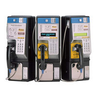
User Manuals: Protel EL1230 CARTE Display Payphone
Manuals and User Guides for Protel EL1230 CARTE Display Payphone. We have
1
Protel EL1230 CARTE Display Payphone manual available for free PDF download: User Manual
Protel EL1230 CARTE Display User Manual (64 pages)
Smart Payphone
Brand:
Protel
| Category:
Telephone
| Size: 1 MB
Table of Contents
Table of Contents
3
Warranty
7
Repair
7
Safety Information
8
Quality Assurance and Reliability
8
Environmental Requirements
8
Nickel-Cadmium (Ni-CD) Battery
8
Introduction
11
Introducing the Elite Series
11
General Description
12
Elite Series Product Line
12
El1000
12
El1200
12
EL1230 Standard Display
12
EL1230 CARTE Display
12
EL1230 VF Display
13
EXC Models
13
El1260
13
Components
13
Elite Payphone Housing
13
Construction of the Elite Payphone
13
Internal Parts of the Elite
14
Lower Housing Components
15
Coin Box W/Lid
16
Vault Door
16
Vault Door Lock
16
Coin Box Alarm Switch
16
Terminal Block
16
Flash Electronic Chassis
16
Coin Scanners
16
Electronic Coin Scanner - ECS IIB
16
Medallist Coin Scanner
17
Electronic Coin Scanner - ECS V
17
Dual Solenoid Relay/Hopper and Coin Return Chute Assembly
17
Upper Housing Components
17
Locking Bars
17
Hookswitch Assembly
17
Upper Housing Lock
17
Coin Entrance
18
Coin Release Push Button
18
Handset
18
Hookswitch Plate
18
Top Piece
19
Main Bezel
19
Dial Key Components
19
Upper Housing Interconnect Cable
19
Information Card
19
Hookswitch Cradle
19
Cast Aluminum Backing Plate
20
Function Key Components
20
Redial Button
20
Up/Down Volume Control
20
New Call Button
20
Multi-Function Buttons
21
Language Select Button
21
Change Card Button
21
Speed Dial Buttons
21
Displays
21
Card Reader (EL1200, 1230 & 1260 Only)
22
Display Controller Board
22
Mounting the Payphone
23
Mounting Location
23
Leveling the Mounting Surface
23
Mounting the Backboard
24
Separating the Upper and Lower Housings
24
Removing the Coin Scanner
25
Removing the Chassis Assembly
25
Removing the Coin Box
25
Installing the Security Studs
26
Securing the Payphone to the Mounting Surface
26
Reinstalling the Coin Box
27
Reinstalling the Chassis Assembly
27
Reinstalling the Coin Scanner
27
Connecting the Line Wire to the Terminal Block
28
Connecting the External DC Power (VFD Models Only)
28
Connecting the Upper and Lower Housings Together
29
Appendix A - FLASH Chassis
30
FLASH Chassis Exploded View
31
Appendix B - EL1000 Initialization and Programming
32
Introduction
32
Basic Key Terms
32
Initialization Procedure Basic Steps
32
Initialization and Local Programming for the EL1000
32
Entering the Programming Mode
33
Programming Rules
33
EL1000 Programming Chart
34
Programming Steps Outlined
35
Features Programming
35
Default Programming
38
Resetting the Chassis to Error #7
39
Program the Real Time Clock
39
Diagnostics Codes
40
Call the Management System (Pronet)
40
Appendix C - EL1200, 1230 or 1260 Initialization and Programming
41
Introduction
41
Basic Key Terms
41
Initialization Procedure Basic Steps
41
Initialization and Local Programming for the EL1200, 1230 or 1260 Payphones
41
Entering the Programming Mode
41
Selection #1 - Programming
42
Selection #2 - Call Management System
45
Selection # 3 - Diagnostics
45
Selection #4 - Utilities
45
Payphone Reporting Modes
47
Coin Box Collect
47
Console Programming Chart
48
Appendix D - Programming of Messages for a Standard, CARTE and VF Displays
49
Appendix E - Operational Test Procedure
50
Operational Tests
50
Appendix F - Error Messages
51
Appendix G - Spare Parts List
52
Spare Parts List (Cont'D.)
53
Appendix H - Return Procedures for Parts in And/Or out of Warranty
54
CRN - Customer Return Number - External Procedure
54
Part I- Requesting the Return for Repair of Parts or Equipment
54
Part II - Receipt of Material at Protel
55
Part III - Shipping
55
Appendix I - Information Card Removal, Installation, and Specifications
56
Removal of the Information Card
56
Installation of the Information Card
57
EL1000 Information Card Dimensions
57
Multi-Function Buttons and Display Dimensions
58
Multi-Function Buttons Label Dimensions
58
Appendix J - Handset Replacement and Jumper Settings
59
Replacing the Handset
59
Handset Jumper Settings
60
Handset Jumpers Inside the Upper Housing
60
Handset Jumper on Chassis Assembly
60
Advertisement
Advertisement
Related Products
Protel EL1230 Standard Display
Protel EL1230 VF Display
Protel Elite Series
Protel EL1000
Protel EL1200
Protel Categories
Microphone
Telephone
Card Reader
Timer
More Protel Manuals
Login
Sign In
OR
Sign in with Facebook
Sign in with Google
Upload manual
Upload from disk
Upload from URL