Sign In
Upload
Manuals
Brands
ProSoft Manuals
Conference System
CompactLogix MVI69L-MBS
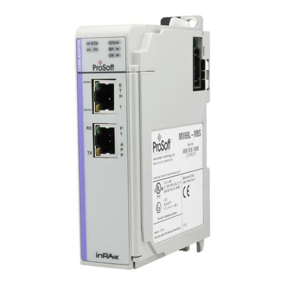
ProSoft CompactLogix MVI69L-MBS Manuals
Manuals and User Guides for ProSoft CompactLogix MVI69L-MBS. We have
1
ProSoft CompactLogix MVI69L-MBS manual available for free PDF download: User Manual
ProSoft CompactLogix MVI69L-MBS User Manual (130 pages)
Modbus Serial Lite Communication Module
Brand:
ProSoft
| Category:
Conference System
| Size: 4 MB
Table of Contents
Your Feedback Please
2
How to Contact Us
2
Content Disclaimer
2
Important Safety Information
3
Table of Contents
4
1 Start here
7
System Requirements
7
Deployment Checklist
8
Package Contents
9
Setting Jumpers
10
Installing the Module in the Rack
11
2 Adding the Module to Rslogix
15
Creating the Module in an Rslogix 5000 Project
15
Creating a Module in the Project Using an Add-On Profile
16
Creating a Module in the Project Using a Generic 1769 Module Profile
20
Installing Prosoft Configuration Builder
22
Generating the AOI (.L5X File) in Prosoft Configuration Builder
23
Setting up the Project in PCB
23
Creating and Exporting the .L5X File
25
Creating a New Rslogix 5000 Project
27
Importing the Add-On Instruction
28
Adding Multiple Modules in the Rack (Optional)
32
Adding an Additional Module in PCB
32
Adding Another Module in Rslogix 5000
34
3 Configuring the MVI69L-MBS Using PCB
41
Basic PCB Functions
41
Creating a New PCB Project and Exporting an .L5X File
41
Renaming PCB Objects
41
Editing Configuraiton Parameters
41
Printing a Configuration File
44
Module Configuration Parameters
44
Module Parameters
44
MBS Port 1 Parameters
45
Modbus Port 1 Commands
49
Ethernet 1
51
Downloading the Configuration File to the Processor
52
Uploading the Configuration File from the Processor
54
4 MVI69L-MBS Backplane Data Exchange
57
General Concepts of the MVI69L-MBS Data Transfer
57
Backplane Data Transfer
57
Normal Data Transfer
58
Write Block: Request from the Processor to the Module
58
Read Block: Response from the Module to the Processor
59
Read and Write Block Transfer Sequences
59
Data Flow between the Module and Processor
60
Slave Mode
60
Master Mode
62
5 Using Controller Tags
64
Controller Tags
64
MVI69L-MBS Controller Tags
65
User-Defined Data Types (Udts)
65
MVI69L-MBS User-Defined Data Types
66
MBS Controller Tag Overview
67
Mbs.config
67
Mbs.data
67
Mbs.control
68
Mbs.status
71
Mbs.util
72
6 Diagnostics and Troubleshooting
73
Ethernet LED Indicators
73
LED Status Indicators
74
Clearing a Fault Condition
74
Troubleshooting
75
Connecting the PC to the Module's Ethernet Port
76
Setting up a Temporary IP Address
77
Using the Diagnostics Menu in PCB
79
Diagnostics Menu
81
Monitoring General Information
81
Monitoring Network Configuration Information
82
Monitoring Backplane Information
82
Port 1 Module Information
83
Communication Error Codes
84
Monitoring Data Values in the Module's Database
84
Standard MODBUS Protocol Exception Code Errors
84
Module Communication Error Codes
84
Command List Entry Errors
85
Connecting to the MVI69L-MBS Webpage
85
Connecting to the Module's Web Page
85
7 Reference
87
Product Specifications
87
MVI69L General Specs
87
Hardware Specifications
88
General Specifications - Modbus Master/Slave
88
About the Modbus Protocol
89
Modbus Master
89
Modbus Slave
89
Function Codes Supported by the Module
90
Read Coil Status (Function Code 01)
90
Read Input Status (Function Code 02)
91
Read Holding Registers (Function Code 03)
93
Read Input Registers (Function Code 04)
94
Force Single Coil (Function Code 05)
95
Preset Single Register (Function Code 06)
96
Diagnostics (Function Code 08)
97
Force Multiple Coils (Function Code 15)
98
Preset Multiple Registers (Function Code 16)
100
Floating-Point Support
101
ENRON Floating Point Support
101
Configuring the Floating Point Data Transfer
102
Function Blocks
106
Event Command Blocks (1000 to 1255)
107
Slave Polling Disable Block (3000)
108
Slave Polling Enable Blocks (3001)
108
Slave Polling Status Block (3002 to 3006)
109
Command Control Blocks (5001 to 5006)
110
Add Event with Data Block (8000)
111
Get Event with Data Status Block (8100)
112
Get Configuration File Information Block (9000 or -9000)
112
Get Configuration File Block (9001 or -9001)
113
Get General Module Status Data Block (9250)
114
Set Port and Command Active Bits Block (9500)
115
Get Port and Command Active Bits Block (9501)
116
Pass-Through Formatted Block for Functions 6 and 16 with Word Data Block (9956)
116
Pass-Through Formatted Block for Functions 6 and 16 with Float Data Block (9957)
117
Pass-Through Formatted Block for Function 5 (9958)
118
Pass-Through Formatted Block for Function 15 (9959)
119
Pass-Through Formatted Block for Function 23 (9961)
120
Pass-Through Block for Function 99 (9970)
120
Set Module Time Using Received Time Block (9972)
121
Pass Module Time to Processor Block (9973)
122
Reset Status Block (9997)
122
Warm-Boot Control Block (9998)
123
Cold-Boot Control Block (9999)
123
Ethernet Port Connection
124
Ethernet Cable Specifications
124
Modbus Application Port Connection
125
Wiring
125
Wiring
128
DB9 to RJ45 Adaptor (Cable 14)
129
8 Support, Service & Warranty
130
Contacting Technical Support
130
Warranty Information
130
Advertisement
Advertisement
Related Products
ProSoft inRAx MVI71-GSC
ProSoft MVI69E-MBS
ProSoft MVI69E-MBTCP
ProSoft MVI69E-AFC
ProSoft MVI56E-AFC
ProSoft MVI56E-MCMR
ProSoft inRAx MVI56-MNETCR
ProSoft MVI56E-GEC
ProSoft inRAx MVI46-BSAPS
ProSoft MVI71-HART
ProSoft Categories
Control Unit
Gateway
Network Hardware
Recording Equipment
Server
More ProSoft Manuals
Login
Sign In
OR
Sign in with Facebook
Sign in with Google
Upload manual
Upload from disk
Upload from URL