
Subscribe to Our Youtube Channel
Related Manuals for ProSoft CompactLogix MVI69L-MBS

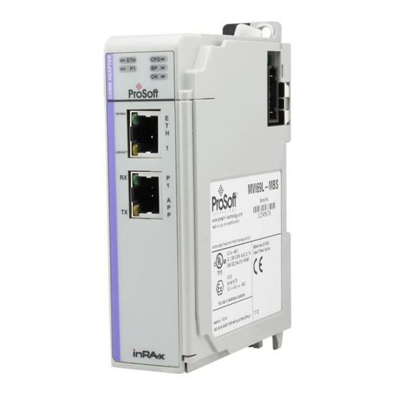
Summary of Contents for ProSoft CompactLogix MVI69L-MBS
- Page 1 MVI69L-MBS CompactLogix™ Platform Modbus Serial Lite Communication Module May 21, 2020 USER MANUAL...
-
Page 2: Your Feedback Please
Neither ProSoft Technology nor any of its affiliates or subsidiaries shall be responsible or liable for misuse of the information contained herein. Information in this document including illustrations, specifications and dimensions may contain technical inaccuracies or typographical errors. -
Page 3: Important Safety Information
Before operating the reset switch, be sure the area is known to be non-hazardous. If the equipment is used in a manner not specified by the manufacturer, the protection provided by the equipment may be impaired. Agency Approvals & Certifications Please visit our website: www.prosoft-technology.com ProSoft Technology, Inc. Page 3 of 130... -
Page 4: Table Of Contents
Creating a Module in the Project Using a Generic 1769 Module Profile ....20 Installing ProSoft Configuration Builder ..............22 Generating the AOI (.L5X File) in ProSoft Configuration Builder ......23 2.3.1 Setting Up the Project in PCB ................23 2.3.2... - Page 5 Function Codes Supported by the Module ............. 90 7.2.4 Read Coil Status (Function Code 01) ..............90 7.2.5 Read Input Status (Function Code 02) ..............91 7.2.6 Read Holding Registers (Function Code 03) ............93 ProSoft Technology, Inc. Page 5 of 130...
- Page 6 RS-232 Wiring...................... 125 7.6.2 RS-422 Wiring...................... 128 7.6.3 RS-485 Wiring...................... 128 7.6.4 DB9 to RJ45 Adaptor (Cable 14) ................. 129 Support, Service & Warranty Contacting Technical Support ................130 Warranty Information ................... 130 Page 6 of 130 ProSoft Technology, Inc.
-
Page 7: Start Here
® Rockwell Automation RSLinx communication software version 2.51 or higher ProSoft Configuration Builder (PCB) (included) ProSoft Discovery Service (PDS) (included in PCB) ® Pentium II 450 MHz minimum. Pentium III 733 MHz (or better) recommended ProSoft Technology, Inc. -
Page 8: Deployment Checklist
256-color VGA graphics adapter, 800 x 600 minimum resolution (True Color 1024 x 768 recommended) Note: The Hardware and Operating System requirements in this list are the minimum recommended to install and run software provided by ProSoft Technology . Other third party ®... -
Page 9: Package Contents
DB9 female to 9-pin screw terminal. Used Adapter for RS422 or RS485 connections to Port 1 of the module If any of these components are missing, please contact ProSoft Technology Technical Support for replacement parts. ProSoft Technology, Inc. Page 9 of 130... -
Page 10: Setting Jumpers
Setup pins are not connected, and the module’s firmware cannot be overwritten. The module is shipped with the Setup jumper OFF. If an update of the firmware is needed, apply the Setup jumper to both pins. Page 10 of 130 ProSoft Technology, Inc. -
Page 11: Installing The Module In The Rack
CompactLogix modules. Warning: This module is not hot-swappable! Always remove power from the rack before inserting or removing this module, or damage may result to the module, the processor, or other connected devices. ProSoft Technology, Inc. Page 11 of 130... - Page 12 Move the module back along the tongue-and-groove slots until the bus connectors on the MVI69 module and the adjacent module line up with each other. Page 12 of 130 ProSoft Technology, Inc.
- Page 13 Push the module’s bus lever back slightly to clear the positioning tab and move it firmly to the left until it clicks. Ensure that it is locked firmly in place. Close all DIN-rail latches. ProSoft Technology, Inc. Page 13 of 130...
- Page 14 Start Here MVI69L-MBS ♦ Platform User Manual Modbus Serial Lite Communication Module Press the DIN-rail mounting area of the controller against the DIN-rail. The latches momentarily open and lock into place. Page 14 of 130 ProSoft Technology, Inc.
-
Page 15: Adding The Module To Rslogix
Create a new project in RSLogix 5000. Add the module to the RSLogix 5000 project. There are two ways to do this: You can use the Add-On Profile from ProSoft Technology. This is the preferred way, but requires RSLogix version 15 or later. -
Page 16: Creating A Module In The Project Using An Add-On Profile
Installing an Add-On Profile Download the AOP file (MVI69x_RevX.X_AOP.zip) from the product webpage (found at www.prosoft-technology.com) and extract the files from the zip archive. Make sure you have shut down RSLogix 5000 and RSLinx before you install the Add-On Profile (AOP). - Page 17 PC. Using an Add-On Profile In RSLogix 5000, expand the I/O C folder in the Project tree. ONFIGURATION Right-click the appropriate communications bus, and then click N ODULE ProSoft Technology, Inc. Page 17 of 130...
- Page 18 This opens the Select Module Type dialog box. In the Module Type Vendor Filters area, uncheck all boxes except the P box. A list ECHNOLOGY of ProSoft Technology modules appears in the dialog box. Select the MVI69L-MBS in the list and click C REATE Page 18 of 130...
- Page 19 OK. Note: This module uses a block transfer size of 240 only. Therefore, it uses an I/O T ABLE 242/241 words. The MVI69L-MBS is now visible in the I/O Configuration tree. ProSoft Technology, Inc. Page 19 of 130...
-
Page 20: Creating A Module In The Project Using A Generic 1769 Module Profile
Modbus Serial Lite Communication Module 2.1.2 Creating a Module in the Project Using a Generic 1769 Module Profile This procedure is not required if you installed the ProSoft Technology Add-On Profile for this module. Expand the I/O C folder in the Project tree. Right-click the... - Page 21 User Manual Set the Module Properties values as follows: Value Parameter Enter a module identification string. Example: MVI69L_MBS Name Enter a description for the module. Example: ProSoft Description communication module for Serial Modbus communications. Select D -INT Comm Format Enter the slot number in the rack where the MV69E-MBS Slot module is installed.
-
Page 22: Installing Prosoft Configuration Builder
Installing ProSoft Configuration Builder Use the ProSoft Configuration Builder (PCB) software to configure the module. You can find the latest version of the ProSoft Configuration Builder (PCB) on our web site: www.prosoft-technology.com. The installation filename contains the PCB version number. For example, PCB_4.3.4.5.0238. -
Page 23: Generating The Aoi (.L5X File) In Prosoft Configuration Builder
Generating the AOI (.L5X File) in ProSoft Configuration Builder The following sections describe the steps required to set up a new configuration project in ProSoft Configuration Builder (PCB), and to export the .L5X file for the project. 2.3.1 Setting Up the Project in PCB To begin, start P (PCB). - Page 24 In the Product Line Filter area of the dialog box, click MVI69. In the Select Module Type dropdown list, click MVI69L-MBS, and then click OK to save your settings and return to the ProSoft Configuration Builder window. The MVI69L-MBS icon is now visible in the tree view.
-
Page 25: Creating And Exporting The .L5X File
Edit the Slot Number indicating where the module is placed in the 1769 bus. Click OK to close the Edit – Module dialog box. The .L5X file is now ready to export to the PC/Laptop. ProSoft Technology, Inc. Page 25 of 130... - Page 26 Modbus Serial Lite Communication Module Right-click the MVI69L-MBS icon in the project tree and then click E XPORT AOI F Save the .L5X file to the PC/Laptop in an easily found location, such as Windows Desktop. Page 26 of 130 ProSoft Technology, Inc.
-
Page 27: Creating A New Rslogix 5000 Project
Click the F menu and then choose N Select your CompactLogix controller model. Select R 16 or newer. EVISION Enter a name for your controller, such as My_Controller. Select your CompactLogix chassis type. ProSoft Technology, Inc. Page 27 of 130... -
Page 28: Importing The Add-On Instruction
(JSR) in the MainRoutine to jump to the routine containing the Add-On Instruction. Right-click an empty rung in the routine and choose I MPORT UNGS Page 28 of 130 ProSoft Technology, Inc. - Page 29 Modbus Serial Lite Communication Module User Manual Select the .L5X file that you exported from PCB. This opens the Import Configuration dialog box. Click T under to display the controller tags in the Add-On Instruction. OUTINE ProSoft Technology, Inc. Page 29 of 130...
- Page 30 INAL column to Local:3:I. Do the same for Local:1:O. Note: If your module is located in Slot 1 of the local rack, this step is not required. Click OK to confirm the import. Page 30 of 130 ProSoft Technology, Inc.
- Page 31 When the import is complete, the new Add-On Instruction rung is present. The procedure also imports new user-defined data types, data objects and the Add-On instruction to be used in the project with the MVI69L-MBS. ProSoft Technology, Inc. Page 31 of 130...
-
Page 32: Adding Multiple Modules In The Rack (Optional)
Important: This procedure is for multiple MVI69L-MBSs running in the same CompactLogix rack You can add additional modules of the same type to the rack. Add a new MVI69L-MBS to the ProSoft Configuration Builder (PCB) project. Export the module configuration as an L5X file. - Page 33 Configure the module parameters. See Module Configuration Parameters (page 44) and then export the AOI .L5X file for the new module (right-click the module and choose E AOI F . See Creating and Exporting the .L5X XPORT File. ProSoft Technology, Inc. Page 33 of 130...
-
Page 34: Adding Another Module In Rslogix 5000
You must be using RSLogix version 15 or later to to use an AOP. If using an AOP is not an option, select G 1769 M and click ENERIC ODULE REATE Page 34 of 130 ProSoft Technology, Inc. - Page 35 Click OK. The new module is now visible. You must also import the Add-On Instruction (AOI) for the new module. In the Controller Organizer pane, double-click M to open the ladder for OUTINE the routine. ProSoft Technology, Inc. Page 35 of 130...
- Page 36 Adding the Module to RSLogix MVI69L-MBS ♦ Platform User Manual Modbus Serial Lite Communication Module … Right-click an empty rung in the routine, and then choose I MPORT UNGS Page 36 of 130 ProSoft Technology, Inc.
- Page 37 Select the .L5X file you created and exported for the new module, and click . Recall that the new .L5X file has a unique filename that is specific to MPORT the new module. ProSoft Technology, Inc. Page 37 of 130...
- Page 38 This opens the I dialog box. Click T to show the MPORT ONFIGURATION controller tags in the AOI. You must edit the F column of the tags INAL for the second module to make them unique. Page 38 of 130 ProSoft Technology, Inc.
- Page 39 2, change the F to Local:2:I and Local:2:O. Also, you INAL can append a ‘_2’ at the end of the F of ‘AOI69_MBS’ and ‘MBS’ INAL arrays as shown below. ProSoft Technology, Inc. Page 39 of 130...
- Page 40 Adding the Module to RSLogix MVI69L-MBS ♦ Platform User Manual Modbus Serial Lite Communication Module 11 Click OK. The setup procedure is now complete. Save the project. It is ready to download to the CompactLogix processor. Page 40 of 130 ProSoft Technology, Inc.
-
Page 41: Configuring The Mvi69L-Mbs Using Pcb
Uploading the Configuration File from the Processor ......54 ProSoft Configuration Builder (PCB) provides a quick and easy way to manage module configuration files customized to meet your application needs. You build and edit the module’s configuration in ProSoft Configuration Builder. - Page 42 Note: Depending on the parameter, you must enter text, or a valid number, or select from a list of options. Click OK to save your changes. Double-click any icon to open an Edit dialog box with a table. Use this dialog box to build and edit Modbus Master commands. Page 42 of 130 ProSoft Technology, Inc.
- Page 43 Configuring the MVI69L-MBS Using PCB Modbus Serial Lite Communication Module User Manual To add a row to the table, click A To edit the row, click E . This opens an Edit dialog box. ProSoft Technology, Inc. Page 43 of 130...
-
Page 44: Printing A Configuration File
240 words of read data (user input data), fixed at module memory 0 to 239. The module uses 240 words of write data (user output data), fixed at module memory 240 to 479. In the ProSoft Configuration Builder (PCB) tree view, double-click the M ODULE icon. -
Page 45: Mbs Port 1 Parameters
MVI69L-MBS ♦ Platform Configuring the MVI69L-MBS Using PCB Modbus Serial Lite Communication Module User Manual 3.2.2 MBS Port 1 Parameters In the ProSoft Configuration Builder tree view, double-click the M ODBUS icon. Configuration Parameters Common to Master and Slave Value... - Page 46 This parameter is used only if the Float Flag is Float Offset enabled. For example, if you set the Float Offset value to 100 and the float start parameter to 200, data requests for register 200 use the internal Modbus register 100. Page 46 of 130 ProSoft Technology, Inc.
- Page 47 230, the command errors are copied to the database as follows: 230: error code for command 0 231: error code for command 1 … An error code of 0 means that the command was successfully sent (no error). ProSoft Technology, Inc. Page 47 of 130...
- Page 48 For example, if you set the value to 250, a request for address 0 corresponds to the register 250 in the database. Note: In Pass-Through mode, this range is limited to 0 to 240. Page 48 of 130 ProSoft Technology, Inc.
-
Page 49: Modbus Port 1 Commands
Modbus Serial Lite Communication Module User Manual 3.2.3 Modbus Port 1 Commands This section defines the master command list specifications for a Master port. In the ProSoft Configuration Builder tree view, double-click the M ODBUS icon. OMMANDS In order to interface the MVI69L-MBS with Modbus slave devices, you must create a command list. - Page 50 1 to 247. If set to zero, the command is a broadcast message on the network. The Modbus protocol permits broadcast commands for write operations. Do not use this node address for read operations. Page 50 of 130 ProSoft Technology, Inc.
-
Page 51: Ethernet 1
32-character text field. Comment 3.2.4 Ethernet 1 This section defines the permanent IP address, Subnet Mask, and Gateway of the module. In the ProSoft Configuration Builder tree view, double-click the E 1 icon. THERNET Description Parameter Unique IP address assigned to the module... -
Page 52: Downloading The Configuration File To The Processor
MVI69L-MBS ♦ Platform User Manual Modbus Serial Lite Communication Module Downloading the Configuration File to the Processor In the ProSoft Configuration Builder tree view, right-click the module icon and choose D OWNLOAD FROM EVICE In the Download Configuration File dialog box, click RSW Page 52 of 130 ProSoft Technology, Inc. - Page 53 Browse to, and then highlight the CompactLogix processor and click OK. Notice the CIPConnect path has been updated in the Download Configuration File dialog box. Click T to verify the path is active and can ONNECTION successfully connect to the processor. ProSoft Technology, Inc. Page 53 of 130...
-
Page 54: Uploading The Configuration File From The Processor
After rebooting, the ladder logic sends the configuration data from the processor to the module. When that is complete, the module starts Modbus communications. Uploading the Configuration File from the Processor In the ProSoft Configuration Builder tree view, right-click the MVI69L-MBS icon and choose U PLOAD FROM EVICE TO Page 54 of 130 ProSoft Technology, Inc. - Page 55 In the Upload Configuration File dialog box, the CIPConnect path should already be constructed if you have previously downloaded the configuration file from the same PC. If not, click RSW , browse to, and then select the CompactLogix Processor, and click OK. ProSoft Technology, Inc. Page 55 of 130...
- Page 56 ONNECTION connect to the processor. When ready, click U . When upload is complete, click C PLOAD LOSE ProSoft Configuration Builder now displays the uploaded configuration file. Page 56 of 130 ProSoft Technology, Inc.
-
Page 57: Mvi69L-Mbs Backplane Data Exchange
The processor inserts data to the module's output image to transfer to the module. The module's program extracts the data and places it in the module's internal database. The output image for the module is 241 words. ProSoft Technology, Inc. Page 57 of 130... -
Page 58: Normal Data Transfer
Description Length (words) Offset Write Block ID Write Data 1 to 240 The Write Block ID is an index value that determines the location in the module’s database where the data is placed. Page 58 of 130 ProSoft Technology, Inc. -
Page 59: Read Block: Response From The Module To The Processor
The backplane parameters are configured as follows: Database address 0 to 239 is continuously transferred from the module to the processor. Database address 240 to 479 is continuously transferred from the processor to the module. ProSoft Technology, Inc. Page 59 of 130... -
Page 60: Data Flow Between The Module And Processor
In Slave Pass-Through mode, write commands from the Master are handled differently than they are in Normal mode. In Slave Pass-Through mode, all write requests are passed directly to the processor and data is not written directly into the module’s database. Page 60 of 130 ProSoft Technology, Inc. - Page 61 This gives the ladder logic the opportunity to also change the values stored in these addresses, if need be, before they are written to the database. Note: The ReadData array is not used in Pass-Through mode. Same as normal mode. Same as normal mode. ProSoft Technology, Inc. Page 61 of 130...
-
Page 62: Master Mode
Master driver for processing. Data received from a slave in response to a read command is stored in the module’s internal database. Status is returned to the processor for each command in the Master Command List. Page 62 of 130 ProSoft Technology, Inc. - Page 63 For a port to function in Master Mode, its Master Command List must be defined in Prosoft Configuration Builder; refer to Modbus Port 1 Commands (page 49). This list contains up to 30 individual entries, with each entry containing the information required to construct a valid command.
-
Page 64: Using Controller Tags
The MVI69L-MBS Add-On Instruction is extensively commented to provide information on the purpose and function of each user-defined data type and controller tag. For most applications, the Add-On Instruction works without needing any modification. Page 64 of 130 ProSoft Technology, Inc. -
Page 65: Mvi69L-Mbs Controller Tags
User-Defined subfolder, located in the Data Types folder in the Controller Organizer pane of the main RSLogix window. Like the controller tags, the UDTs are organized in a multiple-level tree structure. ProSoft Technology, Inc. Page 65 of 130... -
Page 66: Mvi69L-Mbs User-Defined Data Types
ReadData and WriteData. Both of these are 240-element integer arrays. Notice that these UDTs are the data types used to declare the MBS.DATA.ReadData and MBS.DATA.WriteData controller tag arrays. The UDTs are commented in the D column. ESCRIPTION Page 66 of 130 ProSoft Technology, Inc. -
Page 67: Mbs Controller Tag Overview
Generic tags used for internal ladder processing (DO NOT MODIFY) MBS.UTIL 5.3.1 MBS.CONFIG When ProSoft Configuration Builder (PCB) downloads the configuration file from the PC to the processor, the processor stores the configuration file data in the MBS.CONFIG.FileData array. Its CRC is also included in this array. -
Page 68: Mbs.control
Swap code 0 = no swap, 1 = word swap, 2 = words & SwapCode byte swap, 3 = byte swap Modbus function code (1,2,3,4,5,6,15, or 16) ModbusFunctionCode 0 to 9999 Modbus address of the target slave database DeviceDBAddress Event status returned by the module EventCmdStatusReturned Page 68 of 130 ProSoft Technology, Inc. - Page 69 ID x (0-based). 1 = Disable slave 0 or 1 Triggers request to read slave status Port1.GetSlavesStatus 0 = Disable, 1 = Enabled Data array with status Port1.SlavesStatus[x] ProSoft Technology, Inc. Page 69 of 130...
- Page 70 0 = Disable, 1 = Enable MBS.CONTROL.WarmBoot This tag allows the processor to Warmboot the module (driver reboot). Description Tag Name Range 0 or 1 Triggers a warm boot the module WarmBoot 0 = Disable, 1 = Enable Page 70 of 130 ProSoft Technology, Inc.
-
Page 71: Mbs.status
For a slave port, this field contains the value of the last error Port1PreviousErr code returned. For a master port, this field contains the index of the command with an error. ProSoft Technology, Inc. Page 71 of 130... -
Page 72: Mbs.util
Event Command with Data is completed Timer used to clear both cold and warm boot requests BootTimer Holds variables used for processing pass-through messages PassThru[ ] Array Page 72 of 130 ProSoft Technology, Inc. -
Page 73: Diagnostics And Troubleshooting
You can view status data contained in the module through the Ethernet port, using the troubleshooting and diagnostic capabilities of ProSoft Configuration Builder (PCB). You can transfer status data values from the module to processor memory and can monitor them in the processor manually or by customer-created logic. -
Page 74: Led Status Indicators
Verify correct configuration data is being transferred to the module from the CompactLogix controller. If the module's OK LED does not turn GREEN, verify that the module is inserted completely into the rack. If this does not cure the problem, contact ProSoft Technology Technical Support. Page 74 of 130... -
Page 75: Troubleshooting
User Manual 6.2.2 Troubleshooting Use the following troubleshooting steps if you encounter problems when the module is powered up. If these steps do not resolve your problem, please contact ProSoft Technology Technical Support. Processor Errors Steps to take Problem description... -
Page 76: Connecting The Pc To The Module's Ethernet Port
ETH1 Port, and the other end to an Ethernet hub or switch accessible from the same network as the PC. Or, connect directly from the Ethernet Port on the PC to the ETH 1 Port on the module. Page 76 of 130 ProSoft Technology, Inc. -
Page 77: Setting Up A Temporary Ip Address
6.3.1 Setting Up a Temporary IP Address Important: ProSoft Configuration Builder (PCB) locates MVI69L-MBSs through UDP broadcast messages. These messages may be blocked by routers or layer 3 switches. In that case, ProSoft Discovery Service is unable to locate the modules. - Page 78 Important: The temporary IP address is only valid until the next time the module is initialized. For information on how to set the module’s permanent IP address, see Ethernet 1 (page 51). Close the ProSoft Discovery Service window. Enter the temporary IP address in the E...
-
Page 79: Using The Diagnostics Menu In Pcb
ProSoft Configuration Builder (PCB) provides diagnostic menus for debugging and troubleshooting. To connect to the module’s Configuration/Debug Ethernet port In the tree view in ProSoft Configuration Builder, right-click the MVI69L-MBS and then choose D . For instructions on opening and using a... - Page 80 Click T ONNECTION verify that the module is accessible with the current settings. If the T is successful, click C . The Diagnostics ONNECTION ONNECT window is now visible. Page 80 of 130 ProSoft Technology, Inc.
-
Page 81: Diagnostics Menu
Ethernet configuration port. The menu is arranged as a tree structure. 6.4.2 Monitoring General Information In the Diagnostics window in ProSoft Configuration Builder, click MODULE and then click V to view module version information. ERSION ProSoft Technology, Inc. -
Page 82: Monitoring Network Configuration Information
MVI69L-MBS ♦ Platform User Manual Modbus Serial Lite Communication Module 6.4.3 Monitoring Network Configuration Information In the Diagnostics window in Prosoft Configuration Builder, click NETWORK and then click C to view the Ethernet network configuration information. ONFIG 6.4.4 Monitoring Backplane Information In the Diagnostics window in ProSoft Configuration Builder, click BACKPLANE to view the backplane information. -
Page 83: Port 1 Module Information
Slave Status List (Status of each slave on the network, used when port is configured as a Modbus master) Master Command Status (Status code for each master command, used when port is configured as a Modbus master) ProSoft Technology, Inc. Page 83 of 130... -
Page 84: Communication Error Codes
MVI69L-MBS ♦ Platform User Manual Modbus Serial Lite Communication Module 6.4.6 Monitoring Data Values in the Module’s Database In the Diagnostics window in ProSoft Configuration Builder, click DATABASE to view the contents of the MVI69L-MBS’s internal and then click D ECIMAL database. -
Page 85: Command List Entry Errors
PCB. In the PCB Diagnostics window, click the S button. ONNECTION In the Connection Setup dialog box, click B ) to start ProSoft ROWSE EVICE Discovery Service. ’ Right-click the module icon and choose V... - Page 86 Diagnostics and Troubleshooting MVI69L-MBS ♦ Platform User Manual Modbus Serial Lite Communication Module Page 86 of 130 ProSoft Technology, Inc.
-
Page 87: Reference
Sample Add-On Instruction file included. Configuration data obtained from and stored in the processor. Supports CompactLogix processors with 1769 I/O bus capability and at least 800 mA of 5 VDC backplane current available. ProSoft Technology, Inc. Page 87 of 130... -
Page 88: Hardware Specifications
17: Report Slave ID (Slave Only) 5: Force (Write) Single Coil 22: Mask Write Holding 6: Preset (Write) Single Register (Slave Only) Holding Register 23: Read/Write Holding 8: Diagnostics (Slave Only, Registers (Slave Only) Responds to Subfunction 00) Page 88 of 130 ProSoft Technology, Inc. -
Page 89: About The Modbus Protocol
Master port, or from the CompactLogix processor. 1 to 247 (software selectable) Node address Error codes, counters and port status available per configured Status Data slave port ProSoft Technology, Inc. Page 89 of 130... -
Page 90: Function Codes Supported By The Module
The following table is a sample read output status request to read coils 0020 to 0056 (37 coils) from slave device number 11. Note: This is the structure of the message being sent out to the Modbus network. The byte values below are in hexadecimal display Page 90 of 130 ProSoft Technology, Inc. -
Page 91: Read Input Status (Function Code 02)
The inputs are numbered form zero; (input 10001 = zero, input 10002 = one, input 10003 = two, and so on, for a 584). ProSoft Technology, Inc. Page 91 of 130... - Page 92 35 HEX = 0011 0101 (binary) contains the status of only 6 inputs (10213 to 102180) instead of 8 inputs. The two left-most bits are provided as zeros to fill the 8-bit format. Page 92 of 130 ProSoft Technology, Inc.
-
Page 93: Read Holding Registers (Function Code 03)
In the example below, the registers 40108 to 40110 have the decimal contents 555, 0, and 100 respectively. Function Byte High High High Error Check Node Code Count Data Data Data Data Data Data Field Address (2 bytes) ProSoft Technology, Inc. Page 93 of 130... -
Page 94: Read Input Registers (Function Code 04)
In the example below the register 30009 contains the decimal value 0. Function Byte Count Data Input Data Input Error Check Node Code Register High Register Low Field Address (2 bytes) Page 94 of 130 ProSoft Technology, Inc. -
Page 95: Force Single Coil (Function Code 05)
Address The forcing of a coil via Modbus function 5 happens regardless of whether the addressed coil is disabled or not (In ProSoft products, the coil is only affected if you implement the necessary ladder logic). Note: The Modbus protocol does not include standard functions for testing or changing the DISABLE state of discrete inputs or outputs. -
Page 96: Preset Single Register (Function Code 06)
The response to a preset single register request is to re-transmit the query message after the register has been altered. Function Data Register Data Register Preset Data Preset Data Error Check Node Code High Register High Register Low Field (2 bytes) Address Page 96 of 130 ProSoft Technology, Inc. -
Page 97: Diagnostics (Function Code 08)
(A5 37 hex). Response Request (Hex) Field Name (Hex) Field Name Function Function Sub-function Hi Sub-function Hi Sub-function Lo Sub-function Lo Data Hi Data Hi Data Lo Data Lo ProSoft Technology, Inc. Page 97 of 130... -
Page 98: Force Multiple Coils (Function Code 15)
(1= ON, 0= OFF). The use of slave address 0 (Broadcast Mode) forces all attached slaves to modify the desired coils. Note: Functions 5, 6, 15, and 16 are the only messages (other than Loopback Diagnostic Test) that are recognized as valid for broadcast. Page 98 of 130 ProSoft Technology, Inc. - Page 99 Coils that are not programmed in the controller logic program are not automatically cleared upon power up. Thus, if such a coil is set ON by function code 15 and (even months later) an output is connected to that coil, the output is hot. ProSoft Technology, Inc. Page 99 of 130...
-
Page 100: Preset Multiple Registers (Function Code 16)
Func Data Start Data Start Number Number Error Check Node Code Address Address of Points of Points Field (2 bytes) Address High High Page 100 of 130 ProSoft Technology, Inc. -
Page 101: Floating-Point Support
7000 are presumed to contain floating- point values. The significance to this is that the count descriptor for a data transfer now denotes the number of floating-point values to transfer, instead of the number of words. ProSoft Technology, Inc. Page 101 of 130... -
Page 102: Configuring The Floating Point Data Transfer
(example 47101 and 47102 represent TEMP Pump #1), then you do not need to set the Float Flag, or Float Start for the module for Modbus FC 6 or 16 commands being written to the slave. The next few pages show three specific examples: Page 102 of 130 ProSoft Technology, Inc. - Page 103 Addr in Dev - Tells the master where in the slave's database to locate the data. In the above example, the master's Modbus command to transmit inside the Modbus packet is as follows. ProSoft Technology, Inc. Page 103 of 130...
- Page 104 In the above example, the master's Modbus command to transmit inside the Modbus packet is as follows. Data Slave Function Address in Byte Address Code Device Count Count 7100 85.37 BD 71 42 AA 1B BC 00 02 Page 104 of 130 ProSoft Technology, Inc.
- Page 105 Slave Address Function Code Address in Device Reg Count 6100 00 02 17 D4 In the above example the (Enron/Daniel supporting) slave's Modbus command to transmit inside the Modbus packet is as follows. ProSoft Technology, Inc. Page 105 of 130...
-
Page 106: Function Blocks
Pass-through formatted block for function 23 9961 Pass-through block for function 99 9970 Set module time using received time 9972 Pass module time to processor 9973 Reset status block 9997 Warm-boot control block 9998 Cold-boot control block 9999 Page 106 of 130 ProSoft Technology, Inc. -
Page 107: Event Command Blocks (1000 To 1255)
Result of the event request. 1 = the command was placed in the command queue; 0 = no room was found in the command queue. Number of commands in the command queue for the specified port. Spare 4 to 239 ProSoft Technology, Inc. Page 107 of 130... -
Page 108: Slave Polling Disable Block (3000)
Write Block ID: To be used by the processor in its next Write block. Number of slaves processed in the last request. This number should match the value passed in Word 1of the request block. Spare 3 to 299 Page 108 of 130 ProSoft Technology, Inc. -
Page 109: Slave Polling Status Block (3002 To 3006)
Number of slaves in this block Slave polling status data 4 to 61 Spare 62 to 239 Slave Status values Description Value Exceeded retry count and in error delay count mode Block 3000 or 3100 ProSoft Technology, Inc. Page 109 of 130... -
Page 110: Command Control Blocks (5001 To 5006)
Write Block ID: To be used by the processor in its next Write block. Number of commands in the block placed in the command queue. Number of commands in the command queue for the specified port. Spare 4 to 239 Page 110 of 130 ProSoft Technology, Inc. -
Page 111: Add Event With Data Block (8000)
-2 = Port is not a master port -3 = Port is not active (enabled) -4 = Port busy with previous event command -5 = Invalid Modbus command -6 = Invalid point count for command Spare 3 to 239 ProSoft Technology, Inc. Page 111 of 130... -
Page 112: Get Event With Data Status Block (8100)
Block 9000 or -9000: Request from Module to Processor Description Offset Read Block ID: 9000 or -9000 request for configuration file information from processor Write Block ID: 9000 or -9000 to be used by the processor in its next Write block. Page 112 of 130 ProSoft Technology, Inc. -
Page 113: Get Configuration File Block (9001 Or -9001)
Data length: Same as registers 4-5 of the previous request block 3 to 4 Contents of configuration file. If the size of the configuration file exceeds the block 5 to 239 transfer size, this information is transferred in multiple blocks. ProSoft Technology, Inc. Page 113 of 130... -
Page 114: Get General Module Status Data Block (9250)
Event Command Block Count: Total number of Event Command blocks received from the processor. Command Control Block Count: Total number of Command Control blocks received from the processor. Error Block Count: Total number of block errors recognized by the module. Page 114 of 130 ProSoft Technology, Inc. -
Page 115: Set Port And Command Active Bits Block (9500)
Block 9500: Response from Module to Processor Description Offset Read Block ID: 9500 requested by processor. Write Block ID: To be used by the processor in its next Write block. Spare 2 to 239 ProSoft Technology, Inc. Page 115 of 130... -
Page 116: Get Port And Command Active Bits Block (9501)
Function Code received in the incoming command. The MBS Add-On Instruction handles the receipt of all Modbus write functions and to respond as expected to commands issued by the remote Modbus Master device. Page 116 of 130 ProSoft Technology, Inc. -
Page 117: Pass-Through Formatted Block For Functions 6 And 16 With Float Data Block (9957)
The ladder logic is responsible for parsing and copying the received message and performing the proper control operation as expected by the Master device. The processor must then respond to the Pass-Through block with a write block with the following format. ProSoft Technology, Inc. Page 117 of 130... -
Page 118: Pass-Through Formatted Block For Function 5 (9958)
Block 9958: Response from Processor to Module Description Offset Write Block ID: 9958 Spare 1 to 239 This informs the module that the command has been processed and can be cleared from the Pass-Through queue. Page 118 of 130 ProSoft Technology, Inc. -
Page 119: Pass-Through Formatted Block For Function 15 (9959)
Block 9959: Response from Processor to Module Description Offset Write Block ID: 9959 Spare 1 to 239 This informs the module that the command has been processed and can be cleared from the Pass-Through queue. ProSoft Technology, Inc. Page 119 of 130... -
Page 120: Pass-Through Formatted Block For Function 23 (9961)
The ladder logic is responsible for parsing and copying the received message and performing the proper control operation as expected by the Master device. The processor must then respond to the Pass-Through control block with an output image write block with the following format. Page 120 of 130 ProSoft Technology, Inc. -
Page 121: Set Module Time Using Received Time Block (9972)
Block 9972: Response from Module to Processor Description Offset Read Block ID: 9972 Write Block ID: To be used by the processor in its next Write block. Return code 0=OK, -1=error Spare 3 to 239 ProSoft Technology, Inc. Page 121 of 130... -
Page 122: Pass Module Time To Processor Block (9973)
This block resets the module and port 1 status. Block 9997: Request from Processor to Module Description Offset Write Block ID: 9997 Reset Module status (0=no, else yes) Reset Port 1 status (0=no, else yes) Spare 4 to 239 Page 122 of 130 ProSoft Technology, Inc. -
Page 123: Warm-Boot Control Block (9998)
The firmware reloads the configuration file from the processor to the module and resets all MBS memory, error and status data. Block 9999: Request from Processor to Module Description Offset Write Block ID: 9999 Spare 1 to 239 ProSoft Technology, Inc. Page 123 of 130... -
Page 124: Ethernet Port Connection
RJ-45 PIN 3 Tx+ 1 Tx+ 1 Rx+ 1 Rx+ 6 Tx- 2 Tx- 2 Rx- 2 Rx- 1 Rx+ 3 Rx+ 3 Tx+ 3 Tx+ 2 Rx- 6 Rx- 6 Tx- 6 Tx- Page 124 of 130 ProSoft Technology, Inc. -
Page 125: Modbus Application Port Connection
When the RS-232 interface is selected, the use of hardware handshaking (control and monitoring of modem signal lines) is user definable. If no hardware handshaking is used, here are the cable pin-outs to connect to the port. ProSoft Technology, Inc. Page 125 of 130... - Page 126 The "Use CTS Line" parameter for the port configuration should be set to 'Y' for most modem applications. RS-232: Null Modem Connection (Hardware Handshaking) This type of connection is used when the device connected to the module requires hardware handshaking (control and monitoring of modem signal lines). Page 126 of 130 ProSoft Technology, Inc.
- Page 127 (CTS) on the connector. If the port is configured with the Use CTS Line set to Y, then a jumper is required between the RTS and the CTS lines on the port connection. ProSoft Technology, Inc. Page 127 of 130...
-
Page 128: Wiring
RS-485 and RS-422 Tip If communication in the RS-422 or RS-485 mode does not work at first, despite all attempts, try switching termination polarities. Some manufacturers interpret + and -, or A and B, polarities differently. Page 128 of 130 ProSoft Technology, Inc. -
Page 129: Db9 To Rj45 Adaptor (Cable 14)
MVI69L-MBS ♦ Platform Reference Modbus Serial Lite Communication Module User Manual 7.6.4 DB9 to RJ45 Adaptor (Cable 14) ProSoft Technology, Inc. Page 129 of 130... -
Page 130: Support, Service & Warranty
Configuration/Debug status information LED patterns Details about the interfaced serial, Ethernet or Fieldbus devices Note: For technical support calls within the United States, ProSoft’s 24/7 after-hours phone support is available for urgent plant-down issues. Europe / Middle East / Africa Regional Office North America (Corporate Location) Phone: +1.661.716.5100...
Need help?
Do you have a question about the CompactLogix MVI69L-MBS and is the answer not in the manual?
Questions and answers