Sign In
Upload
Manuals
Brands
Precision Digital Corporation Manuals
Measuring Instruments
PROVU PD6363
Precision Digital Corporation PROVU PD6363 Manuals
Manuals and User Guides for Precision Digital Corporation PROVU PD6363. We have
1
Precision Digital Corporation PROVU PD6363 manual available for free PDF download: Instruction Manual
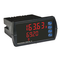
Precision Digital Corporation PROVU PD6363 Instruction Manual (56 pages)
Dual Pulse Input Rate/Totalizer
Brand:
Precision Digital Corporation
| Category:
Measuring Instruments
| Size: 4 MB
Table of Contents
Table of Contents
3
Introduction
6
Ordering Information
6
Specifications
9
General
9
Dual Pulse Inputs
10
Dual Rate/Totalizer
11
Relays
11
Isolated 4-20 Ma Transmitter Output
12
USB Connection
12
On-Board Digital Input (F4)
12
Modbus ® RTU Serial Communications
12
Meterview Pro
12
Compliance Information
13
Safety
13
Electromagnetic Compatibility
13
Safety Information
13
Installation
13
Unpacking
13
Figure 1. 1/8 DIN Panel Cutout Dimensions
14
Figure 2. Panel Mounting Details
14
Figure 3. Meter Dimensions - Side View
14
Figure 4. Meter Dimensions - Top View
14
Panel Mounting Instructions
14
Mounting Dimensions
14
Installation Overview
15
Meterview Pro Software
15
Meterview Pro Installation
15
Figure 11. PD6363-##7 Connectors Label
16
Figure 10. PD6363-##5 Connectors Label
16
Figure 9. PD6363-##4 Connectors Label
16
Figure 8. PD6363-##3 Connectors Label
16
Figure 7. PD6363-##2 Connectors Label
16
Figure 6. PD6363-##0 Connectors Label
16
Figure 5. Transmitter Supply Voltage Selection
16
Power Connections
17
Signal Connections
17
Flowmeter Supply Voltage Selection (P+, P-)
16
Connections
16
Connectors Labeling
16
Figure 18. Switch Input Connections
17
Figure 17. PNP Sensor Powered by Internal Supply
17
Figure 16. NPN Open Collector Input
17
Figure 15. Self-Powered Magnetic Pickup Coil Flowmeter
17
Figure 14. Flowmeters Powered by External Supply
17
Figure 13. Flowmeters Powered by Internal Power Supply
17
Figure 12. Power Connections
17
Modbus RTU Serial Communications
18
Relay Connections
18
Switching Inductive Loads
18
Configure Input Type and Level Switches
17
Figure 21. Low Voltage DC Loads Protection
18
Figure 19. Relay Connections
18
Figure 20. AC and DC Loads Protection
18
Figure 22. F4 Digital Input Connections
19
Figure 24. Analog Output Supply Powering Other Devices
19
Figure 23. 4-20 Ma Output Connections
19
External Relay, Analog Output, & Digital I/O Connections
20
Interlock Relay Feature
20
Remote Operation of Meter
20
4-20 Ma Output Connections
19
Analog Output Transmitter Power Supply
19
F4 Digital Input Connections
19
Figure 25. Expansion Module & DIN Rail Mounting Kit
20
Figure 26. External Relays Module Connections
20
Figure 27. Digital I/O Module Connections
20
Figure 28. Dual 4-20 Ma Output Module Connections
20
Figure 29. Meter to Control Station Connections
20
Figure 30. Interlock Connections
20
Setup and Programming
21
Front Panel Buttons and Status LED Indicators
21
Display Functions & Messages
22
Main Menu
25
Setting Numeric Values
25
Setting up the Meter (Setup)
26
Figure 31. Dual Input Mode (Ud AB)
27
Figure 32. Dual Input Mode (Ud AI)
27
Setting the Input Signal (Input)
27
Setting the Totalizer Features (Total)
27
Setting the Dual-Input Mode (Nmode)
27
Figure 34. Dual Input Mode (Quad 1)
28
Figure 33. Dual Input Mode (Ud BI)
28
Figure 36. Dual Input Mode (Quad 4)
28
Figure 35. Dual Input Mode (Quad 2)
28
Setting the Decimal Point (Dec Pt)
29
Setting the Rate, Total, & Grand Total Units/Tags (Units)
29
Programming the Rate/Totalizer (Prog)
30
Input Calibration Method (Incal)
30
K-Factor Calibration (Fact-A, Fact-B)
30
Scaling the Meter Without a Signal Source (SCAL-A, SCAL-B)
30
Scaling the Meter for Channel a (Scal-A)
31
Error Message (Error)
31
Calibrating the Meter with External Source (CAL-A, CAL-B)
32
Total & Grand Total Setup (Tsetup)
32
Total & Grand Total Reset (Treset)
32
Display Intensity (D-Inty)
33
Setting the Display Parameters & Intensity (Dsplay)
33
Setting the Relay Operation (Relay)
34
Setting the Relay Assignment (Assign)
34
Setting the Relay Action (Act)
34
Programming Set and Reset Points
35
Setting Fail-Safe Operation
35
Programming Time Delay
35
Relay Action for Loss of 4-20 Ma Input (Loop Break)
35
Relay and Alarm Operation Diagrams
35
High Alarm Operation (Set > Reset)
35
Low Alarm Operation (Set < Reset)
36
High Alarm with Fail-Safe Operation (Set > Reset)
36
Low Alarm with Fail-Safe Operation (Set < Reset)
36
Time Delay Operation
36
Pump Alternation Control Operation
37
Relay Sampling Operation
37
Relay Operation Details
38
Overview
38
Relays Auto Initialization
38
Fail-Safe Operation
38
Front Panel Leds
38
Latching and Non-Latching Relay Operation
38
Non-Latching Relay (Auto)
39
Non-Latching Relay with Manual Reset (A-Nman)
39
Latching Relay (Latch)
39
Latching Relay with Clear (Lt-Clr)
39
Acknowledging Relays
39
Setting up the Interlock Relay (Force On) Feature
40
Scaling the 4-20 Ma Analog Output (Aout)
40
Reset Menu (Reset)
40
Manual Control Menu (Contrl)
40
Setting up the Password (Pass)
41
Protecting or Locking the Meter Functions
41
Total Reset Password & Non-Resettable Total
41
Making Changes to a Password Protected Meter
41
Disabling Password Protection
41
Advanced Features Menu
42
Advanced Features Menu & Display Messages
42
Gate Function (Gate)
43
Contact De-Bounce Filter (Filter)
44
Rounding Feature (Round)
44
Modbus RTU Serial Communications (Serial)
44
Select Menu (Select)
45
Input Signal Conditioning (Functn)
45
Multi-Point Linearization (Linear)
45
Math Function (Nmath)
46
Math Constants (Const)
46
Low-Flow Cutoff (Cutoff)
46
Totalizer Count Up/Down (Count)
47
Analog Output Programming (Aoutpr)
47
Programmable Function Keys User Menu (User)
48
Meter Operation
50
Front Panel Buttons Operation
50
Function Keys Operation
50
F4 Operation
50
Maximum/Minimum Readings
50
Troubleshooting
51
Diagnostics Menu (Diag)
51
Testing the Display Leds
51
Determining Software Version
51
Reset Meter to Factory Defaults
51
Factory Defaults & User Settings
52
Troubleshooting Tips
54
EU Declaration of Conformity
55
Advertisement
Advertisement
Related Products
Precision Digital Corporation PROVU Series
Precision Digital Corporation ProtEx Pro PD6800
Precision Digital Corporation ProtEx Max Series
Precision Digital Corporation ProtEX MAX ProtEX MAX PD8-6060-7H7
Precision Digital Corporation ProtEX MAX PD8-6060-7H0
Precision Digital Corporation ProtEX MAX PD8-6060-6H7
Precision Digital Corporation ProtEX MAX PD8-6060-6H0
Precision Digital Corporation PD6400-6R7
Precision Digital Corporation ProtEX-MAX PD8-6060
Precision Digital Corporation PD6603
Precision Digital Corporation Categories
Measuring Instruments
Controller
Cash Counter
Scanner
Racks & Stands
More Precision Digital Corporation Manuals
Login
Sign In
OR
Sign in with Facebook
Sign in with Google
Upload manual
Upload from disk
Upload from URL