Precision Digital Corporation PD8-6310-6H7-WM Manuals
Manuals and User Guides for Precision Digital Corporation PD8-6310-6H7-WM. We have 2 Precision Digital Corporation PD8-6310-6H7-WM manuals available for free PDF download: Instruction Manual
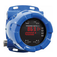
Precision Digital Corporation PD8-6310-6H7-WM Instruction Manual (66 pages)
Explosion-Proof NTEP Certified Batch Controller
Brand: Precision Digital Corporation
|
Category: Controller
|
Size: 3 MB
Table of Contents
Advertisement
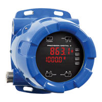
Precision Digital Corporation PD8-6310-6H7-WM Instruction Manual (66 pages)
Explosion-Proof NTEP Certified Batch Controller
Brand: Precision Digital Corporation
|
Category: Controller
|
Size: 2 MB
Table of Contents
Advertisement
Related Products
- Precision Digital Corporation PD8-6310-6H7
- Precision Digital Corporation ProtEX-MAX PD8-6310-6H2-WM
- Precision Digital Corporation ProtEX-MAX PD8-6310-6H4-WM
- Precision Digital Corporation ProtEX-MAX PD8-6310-6H5-WM
- Precision Digital Corporation ProtEX-MAX PD8-6310
- Precision Digital Corporation PD8-6310-7H7
- Precision Digital Corporation ProtEX-MAX PD8-6310-WM
- Precision Digital Corporation ProtEX-MAX PD8-6310-7H2-WM
- Precision Digital Corporation ProtEX-MAX PD8-6310-7H4-WM
- Precision Digital Corporation ProtEX-MAX PD8-6310-7H5-WM