Sign In
Upload
Manuals
Brands
Precision Digital Corporation Manuals
Measuring Instruments
PD8-6262
Precision Digital Corporation PD8-6262 Manuals
Manuals and User Guides for Precision Digital Corporation PD8-6262. We have
2
Precision Digital Corporation PD8-6262 manuals available for free PDF download: Instruction Manual
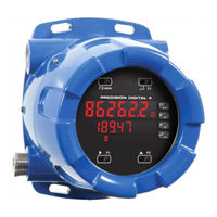
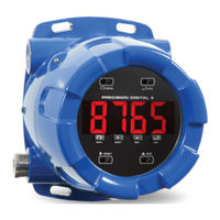
Precision Digital Corporation PD8-6262 Instruction Manual (70 pages)
Explosion-Proof Dual Analog Input Rate/Totalizer
Brand:
Precision Digital Corporation
| Category:
Measuring Instruments
| Size: 6 MB
Table of Contents
Table of Contents
4
Introduction
7
Ordering Information
7
Key Features
9
Specifications
13
General
13
Dual Process Inputs
14
Dual Rate/Totalizer
15
Relays
16
USB Connection
16
Isolated 4-20 Ma Transmitter Output Option
16
RS-485 Serial Communications
16
Modbus ® RTU Serial Communications
16
Digital Input (F4)
17
Digital Inputs & Outputs
17
Meterview Pro Software
17
Compliance Information
17
Electromagnetic Compatibility
17
Product Ratings and Approvals
18
EU Declaration of Conformity
19
Safety Information
19
Installation
19
Unpacking
19
Mounting
20
Figure 1. Enclosure Dimensions - Front View
20
Figure 2. Enclosure Dimensions - Side Cross Section View
20
Installation Overview
22
Meterview Pro Software
22
Transmitter Supply Voltage Selection (P+, P-)
23
Connections
23
Required & Factory Wired Connection
23
Figure 3. Transmitter Supply Voltage Selection
23
Figure 4. Integrated PRO V U Required Connections
23
PRO VU U Electronics Module Layout
24
USB Connection
24
Figure 5. PRO V U Electronics Module Layout
24
Figure 6. USB Connection
24
Power Connections
25
Signal Connections
25
Figure 7. Power Connections
25
Figure 8. 2-Wire Transmitters Powered by Internal Supply
25
Figure 9. 3-Wire Transmitters Powered by Internal Supply
25
Figure 10. Transmitter Powered by External Supply
25
Figure 11. Self-Powered Transmitters
25
Figure 12. 2-Wire Voltage Input Connection
25
Figure 13. 3-Wire Voltage Input Connection
25
RS-485 Connections
26
RS-485 Multi-Drop Connection
26
Figure 14. RS-485 Diagnostic Leds
26
Figure 15. Three-Wire RS-485 Connection
26
Digital I/O Connections
27
F4 Digital Input Connections
27
Remote Programming
27
4-20 Ma Output Connections
27
Analog Output Transmitter Power Supply
27
Figure 16. Digital Input and Output Connections
27
Figure 17. F4 Digital Input Connections
27
Figure 18. 4-20 Ma Output Connections
27
Figure 19. Analog Output Supply Powering Other Devices
27
Relay Connections
28
Interlock Relay Feature
28
Switching Inductive Loads
28
Figure 20. Relay Connections
28
Figure 21. Interlock Connections
28
Figure 22. AC and DC Loads Protection
28
Figure 23. Low Voltage DC Loads Protection
28
Setup and Programming
29
Overview
29
LED Status Indicators
29
Programming Buttons
30
Safetouch Buttons
30
Display Functions & Messages
31
Main Menu
34
Setting Numeric Values
34
Setting up the Totalizer (Setup)
35
Setting the Input Signal (Input)
36
Setting the Totalizer Features (Total)
36
Setting the Rate, Total, & Grand Total Units/Tags (Units)
36
Setting the Decimal Point (Dec Pt)
37
Programming the Rate/Totalizer (Prog)
37
Setting the Display Parameters & Intensity (Dsplay)
40
Display Intensity (D-Inty)
40
Setting the Relay Operation (Relay)
41
Relay and Alarm Operation Diagrams
43
High Alarm Operation (Set > Reset)
43
Low Alarm Operation (Set < Reset)
43
High Alarm with Fail-Safe Operation (Set > Reset)
43
Low Alarm with Fail-Safe Operation (Set < Reset)
43
Time Delay Operation
44
Total Relay Sampling Operation
44
Pump Alternation Control Operation
45
Relay Sampling Operation
45
Relay Operation Details
46
Overview
46
Relays Auto Initialization
46
Fail-Safe Operation
46
Front Panel Leds
46
Latching and Non-Latching Relay Operation
46
Non-Latching Relay (Auto)
47
Non-Latching Relay with Manual Reset (A-Nman)
47
Latching Relay (Latch)
47
Latching Relay with Clear (Lt-Clr)
47
Acknowledging Relays
48
Pump Alternation Control Applications (Altern)
48
Setting up the Interlock Relay (Force On) Feature
49
Scaling the 4-20 Ma Analog Output (Aout)
50
Reset Menu (Reset)
50
Manual Control Menu (Contrl)
50
Setting up the Password (Pass)
51
Protecting or Locking the Totalizer Functions
51
Total Reset Password & Non-Resettable Total
51
Making Changes to a Password Protected Totalizer
51
Disabling Password Protection
51
Advanced Features Menu
52
Advanced Features Menu & Display Messages
52
Noise Filter (Filter)
54
Noise Filter Bypass (Bypass)
54
Rounding Feature (Round)
54
Modbus RTU Serial Communications (Serial)
54
Select Menu (Select)
55
Input Signal Conditioning (Functn)
55
Square Root Linearization (Square)
55
Programmable Exponent Linearization (Prog E)
55
Multi-Point Linearization (Linear)
56
Math Function (Nmath)
56
Math Constants (Const)
56
Low-Flow Cutoff (Cutoff)
56
Totalizer Count Up/Down (Count)
57
Analog Output Programming (Aoutpr)
58
Programmable Function Keys User Menu (User)
59
Internal Calibration (ICAL)
61
Totalizer Operation
62
Button Operation
62
Safetouch Buttons
62
Function Keys Operation
63
Digital Inputs Operation
63
Maximum/Minimum Readings
63
Troubleshooting
64
Diagnostics Menu (Diag)
64
Testing the Display Leds
64
Determining Software Version
64
Reset Totalizer to Factory Defaults
64
Factory Defaults & User Settings
65
Troubleshooting Tips
67
Advertisement
Precision Digital Corporation PD8-6262 Instruction Manual (32 pages)
Brand:
Precision Digital Corporation
| Category:
Measuring Instruments
| Size: 0 MB
Table of Contents
Introduction
3
Model Number Descriptions
4
Ordering Configuration Example
4
Table of Contents
5
Specifications
7
Instrument Specifications
7
General
7
Serial Communications
7
Digital Inputs & Outputs
8
External Switch Contacts
8
Product Ratings and Approvals
9
Compliance Information
10
Safety
10
Electromagnetic Compatibility
10
Safety Information
11
Installation
11
Unpacking
12
Pre-Installed Conduit/Stopping Plug
12
Mounting
12
Cover Jam Screw
12
Connections
13
Required & Factory Wired Connections
13
Figure 1: Integrated Vigilante II (PD8-154-6 & PD8-158-6) Required Connections
14
Figure 2: Integrated Vigilante II (PD8-154-7 & PD8-158-7) Required Connections
15
Figure 3: Integrated Trident X2 (PD8-765) Required Connections
16
Figure 4: Integrated PRO V U Required Connections
17
Digital I/O Connections
18
Figure 5: Digital I/O Connections
18
External Switch Contacts
19
Figure 6: External Switch Contacts
20
Serial Communications Connections
21
Figure 7: Protex-MAX Connections to a Serial Converter
21
Figure 8: RS-485 Wiring
22
Figure 9: RS-485 Two-Wire Multi-Drop Wiring
23
Using PRO V U Serial Adapters
24
Operation
25
Overview
25
Safetouch Buttons
25
Digital I/O
26
Serial Communications Overview
26
Figure 10: General Four-Wire Network Connection
27
Figure 11: General Two-Wire Network Connection
27
Troubleshooting
28
Troubleshooting Tips
28
Service
29
Mounting Dimensions
30
Figure 12: Enclosure Dimensions - Front View
30
Figure 13: Enclosure Dimensions - Side Cross Section View
30
Ec Declaration of Conformity
31
Advertisement
Related Products
Precision Digital Corporation ProtEX-MAX PD8-6200-7H0
Precision Digital Corporation ProtEX-MAX PD8-6200-6H7
Precision Digital Corporation ProtEX-MAX PD8-6200-7H7
Precision Digital Corporation ProtEX-MAX PD8-6200-6H3
Precision Digital Corporation ProtEX-MAX PD8-6200-7H3
Precision Digital Corporation ProtEX-MAX PD8-6200-7H4
Precision Digital Corporation ProtEX-MAX PD8-6200-7H5
Precision Digital Corporation ProtEX-MAX PD8-6200-7H2
Precision Digital Corporation ProtEX-MAX PD8-6200-6H5
Precision Digital Corporation ProtEX-MAX PD8-6200-6H4
Precision Digital Corporation Categories
Measuring Instruments
Controller
Cash Counter
Scanner
Racks & Stands
More Precision Digital Corporation Manuals
Login
Sign In
OR
Sign in with Facebook
Sign in with Google
Upload manual
Upload from disk
Upload from URL