Sign In
Upload
Manuals
Brands
PRACTICAL AUTOMATION Manuals
Printer
ITK 38 SERIES
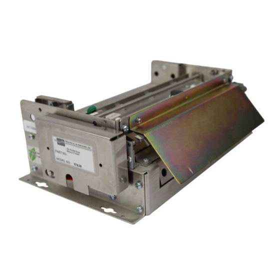
PRACTICAL AUTOMATION ITK 38 SERIES Format Manuals
Manuals and User Guides for PRACTICAL AUTOMATION ITK 38 SERIES Format. We have
1
PRACTICAL AUTOMATION ITK 38 SERIES Format manual available for free PDF download: User Manual
PRACTICAL AUTOMATION ITK 38 SERIES User Manual (79 pages)
Brand:
PRACTICAL AUTOMATION
| Category:
Printer
| Size: 2 MB
Table of Contents
Table of Contents
2
1 How to Contact Us
7
Limited Product Warranty
7
Warranty Terms
7
Warranty Procedure
7
Fcc Notification
8
Regulatory Compliance
8
2 Itk 38 Overview
9
Introduction
9
Product Description
9
Itk 38 Model Number System
10
ITK 38 Power Supply Model Number
10
ITK 38 Printer Model Number Example
11
ITK 38 Separate Component Model Numbers
11
Preparation for Use
12
Unpacking and Inspection
12
Installation Location
12
Power Connection
12
Data I/O Interface Connection
12
Parallel Interface
12
USB Interface
12
Printer Driver Installation
12
Discussion of Printer Drivers
12
Discussion of Driver Names
12
Host Controlled Printer Firmware Update
13
Loading the Printer Driver
13
Printer Utility DLL
13
Printer's Status Information
13
Which Driver to Load
13
Selecting and Configuring the Driver
13
Paper Supply
14
Paper Loading
14
Test Print
14
Operation from the Interface
14
3 Operator Controls and Indicators
15
Switch and Display
15
Panel Leds Indicators
15
Power / Paper
15
Ready
15
Attn. / Error
15
Panel Switches
15
Forcing Reset Initialization
15
Rear I/O Panel
16
4 Panel Switch Operations
17
Switch Modes
17
Offline Operations
17
Offline Switch Operations Table
17
Offline Switch Operations
17
Power-On Operations
17
Power-On Operations Table
17
Printer System Information and Reports
17
System Status Report
18
System Report - for Registration Marked Paper
18
System Report - for Continuous Paper
19
System Information Help Report
20
Diagnostic Menu
21
Change Tof Configurations
21
Eeprom Change Menu
21
R E -Program Flash Memory
21
Hex Dump Diagnostic Mode
21
Printhead Cleaning Diagnostic Mode
21
5 Paper Handling Options & Actions
22
Paper Delivery Output Options
22
Disposing Transport-Presenter
22
Dispose Storage Chamber
22
Loop Storage Chamber
22
Perforated Paper Stock
22
Document Not Taken Status
23
Host Controlled - Document Not Taken Reactions
23
Host Monitoring of Dispose Documents
23
Transport-Presenter Control Parameters and Operating Mode Selection
23
Transport-Presenter Control Parameters for a Document Not Taken
23
Printer Assisted - Document Not Taken Reactions
24
Purge Options - Document Not Taken
25
Transport-Presenter Control Parameters for a Blocked Output Jam
25
Blocked Output
26
Document Not Taken
26
Printer & Host Reactions - Document Not Taken or Blocked Output
26
Cutter with Jam Resistant Output Chamber Option
26
Cutter Only Output Option
26
Tearbar with Jam Resistant Output Chamber Option
26
Minimum Form Length Adjustment
27
Paper Input Delivery Options
28
Formula for Calculating Paper Roll Capacity
28
Paper Roll I.D
28
Internal 6"/8" (152Mm/203Mm) Diameter Paper Roll Holder
28
External 10" Diameter Paper Roll Holder
28
External 10"" Diameter Paper Roll Holder Drawing
28
External Roll Holder Paper Path Recommendations Drawing
29
Externally Located Paper Design Considerations
29
Low Paper Monitoring
29
Low Paper Host Status Information
29
Low Paper Cable Detection
30
Printer Reactions to the Low Paper Conditions
30
6 Paper Information
31
Paper Specifications
31
Paper Width
31
Roll Size
31
Recommended Papers
31
Other Thermal Papers
31
Print Activation Energy
31
Roll Paper Curl Considerations
31
Paper Form Type
31
Paper Supply
31
Paper Pre-Printing Information
32
Cutting Perforated Paper
32
Fan Fold / Perforated Paper
32
Pre-Printed Paper: Bottom Side Restrictions
32
Pre-Printed Paper: Top Side
32
Registration Mark Location: Bottom Side
33
Paper Form Type Recognition
33
Printer Recognition of Paper Form Type
33
Top and Bottom Margins
33
Host PC Recognition of Paper Form Type and Size
33
Paper Form Size Determination
33
Document Length
33
Registration Mark Document Size Measurement
34
Printer Determination of Form Size
34
Autosize Measurement and Save to EEPROM
34
Autosize Measurement of Form Length
34
Continuous Forms
34
Default Form Size
34
Entering a Fixed Form Size into EEPROM Memory
34
Manual Size Data Entry
34
Registration Marked Forms
34
Stored Form Length
34
Reporting Document Length
35
Host Determination of Form Size - Registration Marked Forms
35
7 Printer Programable Configuration Settings
36
Overview
36
I/O PCB Configuration Resistors and Configuration Straps
36
Printer EEPROM Parameter Storage
36
Paper Output Delivery Option Detection
36
Special Customization
36
8 Data and Auxiliary Interfaces
37
Ieee-1284 Parallel Data Interface
37
Parallel Interface Cable
37
Parallel Interface (IEEE-1284) Cable Schematic
37
Parallel Interface Pin-Out Table
37
Parallel Port Signaling
37
Usb Data Interface
37
USB Data Interface Cable
37
Data Interface Cable Quality
37
Auxiliary I/O Connector
37
9 Error Codes
38
Annunciations
38
Sequence Length
38
Weighted Positions
38
Counted
38
Example
38
Error Code Table
39
Error Code Table Notes
39
Error Code Table Information
39
Error Code Computation
39
10 Eeprom Printer Parameter Storage Memory
40
Eeprom Overview
40
Eeprom Change Menu Operation
40
Active and In-Active Menu Line
40
Eeprom Menu #1 Printout
40
Eeprom Menu #1 Parameters
41
Print Intensity
41
Print Energy Table
41
IPS Clamp
41
Power Supply
41
Interface Control
41
Beeper Control
41
Low Paper Actions
41
Purge Spooler on Error
42
Configuration Misc
42
Eeprom Menu #2 Printout
42
Eeprom Menu #2 Parameters
42
Paper Backup
42
Change Stored Size: Form Size 10'S, 1'S, 0.1'S, 0.01'S
42
Stored Size
42
Form Control
42
End of Document Length
43
Autosize
43
Minimum Form Length
43
Status Pointer
43
Blocked Output Jam Error Control
44
Document Not Taken Control
44
Eeprom Menu #3 Printout
44
Eeprom Menu #3 Parameters
44
Parallel Interface
44
Low Paper Cable Detection
45
Eeprom Factory Defaults
45
11 Printer Status Information
46
Itk 38 Printer Status Overview
46
Operator Status
46
Parallel Interface - Compatibility Mode Status
46
Parallel IEEE 1284 Interface Standard
46
Parallel Interface IEEE-1284 Reverse Channel Status
46
Requesting Status Data
46
Reverse Channel Status Data Types
46
Reverse Channel - Detailed Status - Application Program Reading Protocol
47
Reverse Channel Speed
47
Selection of Detailed Status Information
47
Status Data Request
47
Status Group Selection Commands
48
Status Information Data Organization
48
Detailed Status Format (Normal Reverse Channel Status)
48
IEEE 1284 ID String Format (Plug & Play ID String Reverse Channel Status)
48
Status Field Descriptions
49
Status Field Format
49
Status Field Notes
49
Extended Status Group
50
Normal Status Group
50
Short Status Group
50
Short Status Group - Bit Status Format
50
Addressed Status Group
51
Bit Flag Data - Status Field 00
51
Complete Status Group
51
Document Count - Status Field 02
51
Error Code - Status Field 01
51
Printhead Temperature - Status Field 03
51
Capabilities - Status Field 11
52
Firmware Version - Status Field 05
52
Flash Ready Acknowledge Status - Status Field 15
52
Form Length - Status Field 04
52
Plug & Play ID String - Status Field 08
52
Product Electronic Serial Number - Status Field 09
52
Reporting Document Length
52
Field 01 Error Code List
53
12 Operator Re-Programming of Flash Memory Procedure
55
General
55
Requirements
55
Entering the Flash Load Mode
55
Flash Loading Process
55
Warning
55
Flash Loading Completion
55
Flash Loading Time
56
Firmware Data Files
56
13 Host Re-Programming of Flash Memory Procedure
57
Overview
57
Flash Memory Reprogramming Mode Entry
57
Manual Entry
57
Command Entry
57
Flash Read Only Memory Organization
57
Firmware Binary Data Files
57
Flash Memory Reprogramming Actions
58
Command Driven Process for Reprogramming the Flash Memory
58
Command Driven Process Details
60
14 Applications Programmer Information
62
Printer Utility Dll
62
Document
62
Status String Selection
62
Status and Spooler Management
62
Document Re-Present (Eject) and Dispose Commands
62
15 Maintenance
63
Printer Assembly- Maintenance Points
63
Paper Registration Mark Sensor
63
Printhead Alignment & Pressure Cam
63
Printhead Cleaning
63
Printhead Cleaning Diagnostic Mode
64
Printhead Cleaning Sheets
64
Documentation Presenter / Jam Sensors
64
Sensor Access and Alignment Adjustments
64
Document Jam - Requiring Removal of the Head
65
16 Diagnostic
66
General
66
Off-Line Switch Operations
66
Power on Switch
66
Diagnostics
66
Special Functions
66
Burn-In and Cut Tests
66
Hex Dump Mode
66
Data Rate Measurement Test
66
Printhead Cleaning Mode
66
17 Power Information
67
Power Input
67
Power Management
67
Power Supply Requirements
67
Power Supply Additional Requirements
67
18 Appendix
68
Printer Specifications
68
ITK 38 Printer Dimensional Drawings - Cutter with Disposing Transport-Presenter
70
Itk 38 Printer Dimensional Drawings - Optional Output Extension
70
Itk 38 Printer Dimensional Drawings - Cutter with Output Protection Chamber
71
Itk 38 Printer Dimensional Drawings - Cutter Only Output
71
Itk 38 Printer Dimensional Drawings - Tearbar with Output Protection Chamber
72
Itk 38 Printer Dimensional Drawings - Fanfold Paper Tray Model # Atx-Ffphlp
72
ITK 38 Printer Dimensional Drawings - Large (10" Diameter) Paper Roll Holder
73
ITK 38 Printer Dimensional Drawings - Standard (6"/8" Diameter) Paper Roll Holder
73
Itk 38 Printer Dimensional Drawings - 60 Watt Power Supply
74
Itk 38 Printer Dimensional Drawings - 130 Watt Power Supply
75
Connector Pin-Out - 8 Pin Power Connector
75
Connector Pin-Out - 8 Pin Auxiliary Connector
75
Connector Pin-Out 26 Pin Parallel Connector
76
Ieee-1284 Parallel A-B Cable Schematic
77
Test Document (Small)
78
Test Document (Large)
79
Advertisement
Advertisement
Related Products
Practical Automation ITX 3000 series
Practical Automation ITX 2000 series
PRACTICAL AUTOMATION Categories
Printer
More PRACTICAL AUTOMATION Manuals
Login
Sign In
OR
Sign in with Facebook
Sign in with Google
Upload manual
Upload from disk
Upload from URL