Sign In
Upload
Manuals
Brands
PPM Manuals
Test Equipment
Sentinel 3
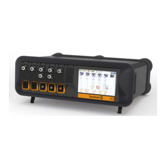
PPM Sentinel 3 Fiber Optic Links Manuals
Manuals and User Guides for PPM Sentinel 3 Fiber Optic Links. We have
1
PPM Sentinel 3 Fiber Optic Links manual available for free PDF download: System & Accessory Handbook
PPM Sentinel 3 System & Accessory Handbook (59 pages)
Brand:
PPM
| Category:
Test Equipment
| Size: 1 MB
Table of Contents
Table of Contents
4
1 Introduction to Fibre Optic Links
10
Initial Inspection
10
Storage
10
Batteries
10
Important Handling Instructions
10
Figure 1: Remote Head and Receiver Module in Transport Case
10
Care of Fibre Optic Interfaces
11
Figure 2: Dirty Fibre Interface Causes Performance Degradation
11
Figure 3: Cleaning Fluid Residue Cross-Contaminates Clean Fibres
11
Figure 4: Clean Interface (I) Mated with Contaminated Interface (II) Results in Permanent Damage (III)
12
2 Quick Installation Guide
13
Module Installation
13
Applying Power
13
Optical Cable Installation
13
Battery Connection
13
Figure 5: Power Button
13
Figure 6: Tx1 Remote Head with Battery Disconnected
13
3 Sentinel 3 System Description
14
Basic System Function
14
Receiver Variants
14
Figure 7: Sentinel 3 Desktop Chassis with Two Rx1, Two Rx2, and One Rx6 Fitted
14
Table 1 Standard and Low-Noise Gain Ranges
14
Setting Gain
15
Standard Gain Range
15
Low Noise Gain Range
15
Figure 8 Transmitter and Receiver Settings for Rx (Left) and Rx+ (Right) Series
15
Sensitivity Versus Compression Modes
16
Thermal Compensation
16
Received Light Level (RLL) Automatic Gain Control (AGC)
16
Figure 9: Sensitivity or Compression Mode Setting
16
Factory Calibration
17
High Impedance Mode
17
Passive Integrator Mode
17
Transmitter Power Modes
17
Chassis
17
Housing
18
Nineteen Inch Rack Chassis
18
Desktop Chassis
18
Figure 10: Nineteen Inch Chassis Dimensions
18
Charger
19
Controller
19
Figure 11: Desktop Chassis Dimensions
19
Figure 12: Rear View of the Interface Panel
19
External Control Interfaces
20
Local Receiver Modules
21
Rx1 Receiver Module
21
Rx2 Receiver Module
21
Figure 13: Rx6 Receiver Module Dimensions
21
Figure 14: Rx6 Receiver Module with Deployed Removal Handle
21
Rx6 Receiver Module
22
Remote Transmit Heads
23
Tx1
23
Figure 15: Single Input Tx1 Remote Transmit Head
23
Figure 16: Tx1 Single Input Remote Transmit Head Dimensions
23
Tx1 Battery Pack
24
Tx8
24
Tx8 Battery Pack
24
Figure 17: Tx8 Eight Input Remote Transmit Head Dimensions
24
Accessories
26
Cable Assemblies
26
Reels
26
Cross-Site Cables
26
Figure 18: Different Cable Reels Available (Dependant on Cable Type and Length)
26
Figure 19: Rx1 Module Cross-Site Cable and Connector
26
Patch Cables
27
Figure 20: Rx2 Module Cross-Site Cable and Connector
27
Figure 21: Rx6 Module Cross-Site Cable and Connector
27
Table 2: Cross-Site Cable Basic Specification
27
Figure 22: Rx1 Module Patch Cable and Connector
28
Figure 23: Rx2 Module Patch Cable and Connector
28
Figure 24: Rx6 Module Patch Cable and Connector
28
Break-Out Boxes
29
Cleaning Kit
29
Figure 25: Rx2 & Rx6 Break-Out Solutions
29
Figure 26: Rx1, Rx2, and Rx6 System Configurations and Break-Out Boxes
29
Table 3: Patch Cable Basic Specification
29
Charge Shoes
30
Figure 27: Residue Free Cleaning Fluid
30
Figure 28: Cleaning Sticks for Rx1, Rx2, & Rx6 Optical Connectors and Cables
30
Figure 29: Dry Fibre Cleaning Tools
30
Battery Charge Display Only
31
Chassis Charging
31
Desk-Top Charging
31
Figure 30: Sentinel 3 Charging Shoe
31
Figure 31: Desktop Charger (Left) and Charge Shoe Status LED States (Right)
31
Inverter Shelf
32
Charge Shelf
32
4 Graphical User Interface
33
Overview Screen
33
Figure 32: Top-Level GUI Display Menu
33
Figure 33: Rx Module Icons (Left: Rx1, Right: Rx2)
33
Figure 34: Tx Head Icons (Left: Tx1, Right: Tx8)
33
Rx Module Screen
34
Tx Head Screen
34
Figure 35: Information Area in Remote Mode
34
Figure 36: Rx Module Screen (Rx6 Connected)
34
Figure 37: Tx Head Screen (Tx8 Connected)
35
Figure 38: Tx Head Screen Popups (Left: Tx Head Power Control, Middle: Input Gain Control, Right: Part Number Etc. View)
35
Warning and Error Messages
36
Alarms
36
Figure 39: Acknowledging the Overdrive Alarm
36
Figure 40: Receiver and Transmitter Warning Message Examples
36
Warnings
37
Charger Screen
37
Settings Screen
37
Figure 41: Charger Screen
37
Figure 42: Settings Screen
38
Figure 43: Settings Screen Access Mode Override
38
Set Static IP Address
38
Updates
39
Update Operating System Image
39
Figure 44: Switching between Dynamic and Static IP Address Assignment
39
Update Application
40
Figure 45 Update Image Button
40
Figure 46 Update Application Button
40
Figure 47 Application and Image Update Screens
40
Shutdown Screen
41
Remote Control Application
41
Figure 48 Shutdown Screen
41
Figure 49 : Sentinel 3 Remote Agent with Manual Commands Disabled (Disconnected)
42
Figure 50: Sentinel 3 Remote Agent with Manual Commands Enabled (Connected to a Sentinel 3 System)
42
Figure 51: Options Menu
43
Figure 52: File Menu
43
Figure 53: Log File Copy Dialog
43
Installation
44
System Requirements
44
5 External Control Interface Command Reference
45
Ethernet Connection
45
Figure 54: Ethernet to GPIB External Adapter
45
Figure 55: USB to GPIB External Adapter
45
Format
46
Figure 56 Suggested Ethernet Connection for Remote Control
46
Remote Commands and Responses
47
Response Times
47
Command Set
48
Measurement Set-Up Commands
48
Table 4: Measurement Set-Up Commands
49
Operational Commands
50
Reporting Commands
50
Table 5: Operational Commands
50
Common Response Strings
51
Table 6: Common Response Strings
52
Legacy Command Comparison
53
Table 7: Legacy Command Comparison
55
6 Software Release Notes (2018-On)
56
7 Maintenance
57
Cables & Connectors
57
Service
57
8 Lithium Battery Transportation
58
Tx1 Battery
58
Tx8 Battery
59
Advertisement
Advertisement
Related Products
PPM Categories
Media Converter
Control Unit
Enclosure
Industrial Electrical
Switch
More PPM Manuals
Login
Sign In
OR
Sign in with Facebook
Sign in with Google
Upload manual
Upload from disk
Upload from URL