Table of Contents
Advertisement
Quick Links
System & Accessory
Document
Summary of Changes
Revision
1.9
Additional features introduced in software release 1.05.000.
Corrections to
1.10
Additional guidance on remote command responses.
New application and image update procedures for software release 1.05.001.
Corrections to GETTXSETTINGS remote command description
1.11
Corrected email and web addresses
Pulse Power & Measurement Ltd, 65 Shrivenham Hundred Business Park, Watchfield, Swindon, Wiltshire SN6 8TY, UK
Sentinel 3
Handbook
Version 1.11
S3x-HB-1-11
CR3991 18/01/19
REPORT
remote command arguments.
Tel +44 (0)1793 784389
Fax +44 (0)1793 784391
Email
sales@ppmtest.com
Web
www.ppmtest.com
Advertisement
Table of Contents

Summary of Contents for PPM Sentinel 3
- Page 1 Sentinel 3 System & Accessory Handbook Version 1.11 S3x-HB-1-11 CR3991 18/01/19 Document Summary of Changes Revision Additional features introduced in software release 1.05.000. Corrections to REPORT remote command arguments. 1.10 Additional guidance on remote command responses. New application and image update procedures for software release 1.05.001.
- Page 2 S3x-HB-1-11 Instrument care and safety information Please read the whole of this section before using your Sentinel 3 product. It contains important safety information and will enable you to get the most from your fibre optic link. Electrical Safety The Sentinel 3 enclosure provides the termination for power inputs and can be fitted with power supplies.
- Page 3 S3x-HB-1-11 For heavy or awkward items, ensure that the correct precautions and safety equipment are implemented to avoid injury and/or damage to equipment. If in doubt, consult your Health & Safety representative.
-
Page 4: Table Of Contents
QUICK INSTALLATION GUIDE ..................... 13 Module installation ....................... 13 Applying power ........................13 Optical cable installation ...................... 13 Battery connection ....................... 13 SENTINEL 3 SYSTEM DESCRIPTION ..................14 Basic system function ......................14 3.1.1 Receiver variants ....................... 14 3.1.2 Setting gain ........................ 15 3.1.2.1 Standard gain range ................... - Page 5 S3x-HB-1-11 3.4.1.1 Tx1 battery pack: ..................24 3.4.2 Tx8 ..........................24 3.4.2.1 Tx8 battery pack: ..................24 Accessories .......................... 26 3.5.1 Cable assemblies....................... 26 3.5.1.1 Reels ......................26 3.5.1.2 Cross-site cables ..................26 3.5.1.3 Patch cables ....................27 3.5.2 Break-out boxes ......................29 3.5.3 Cleaning kit ........................
- Page 6 S3x-HB-1-11 5.4.1 Measurement set-up commands ................48 5.4.2 Operational commands ....................50 5.4.3 Reporting commands ....................50 5.4.4 Common response strings ..................51 Legacy command comparison ..................... 53 SOFTWARE RELEASE NOTES (2018-ON) .................. 56 MAINTENANCE ..........................57 Cables & connectors ......................57 Service ..........................
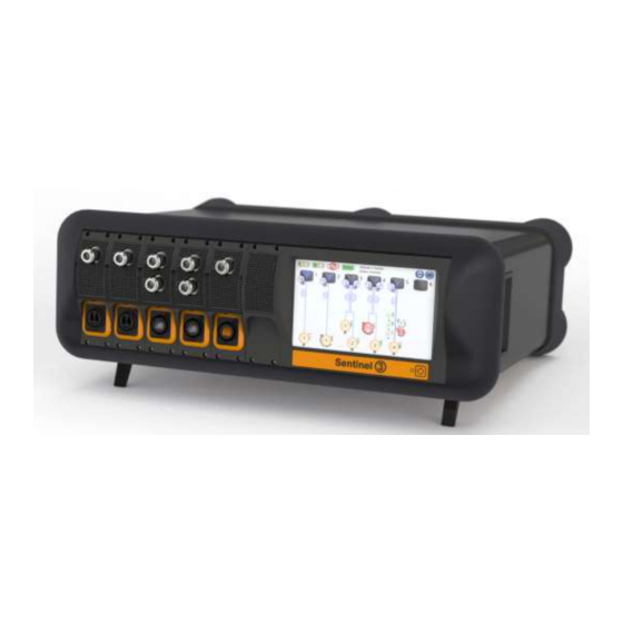
- Page 7 Figure 6: Tx1 remote head with battery disconnected ................13 Figure 7: Sentinel 3 desktop chassis with two Rx1, two Rx2, and one Rx6 fitted ........14 Figure 8 Transmitter and receiver settings for Rx (left) and Rx+ (right) series ........... 15 Figure 9: Sensitivity or compression mode setting ..................
- Page 8 Figure 48 Shutdown screen ........................41 Figure 49 : Sentinel 3 Remote Agent with Manual Commands disabled (disconnected) ......42 Figure 50: Sentinel 3 Remote Agent with Manual Commands enabled (connected to a Sentinel 3 system) ..................................42 Figure 51: Options Menu..........................43 Figure 52: File Menu ...........................
- Page 9 S3x-HB-1-11 Table of tables Table 1 Standard and low-noise gain ranges ..................... 14 Table 2: Cross-site cable basic specification ....................27 Table 3: Patch cable basic specification ..................... 29 Table 4: Measurement set-up commands ....................49 Table 5: Operational commands ......................... 50 Table 6: Common response strings ......................
-
Page 10: Introduction To Fibre Optic Links
1.3 Important handling instructions The Sentinel 3 system is an intricate piece of test equipment so can be seriously damaged if knocked or dropped. Remote heads contain sensitive electro-mechanical components that are susceptible to excessive shock and vibration. -
Page 11: Care Of Fibre Optic Interfaces
It is important to position the alignment key on the cable connector with the matching slot in the module. Single-mode fibre is used for the Sentinel 3 system for its high performance characteristics. As this fibre has a very narrow diameter (9μm) it is far more susceptible to dust contamination than the relatively large area of a multi-mode fibre. -
Page 12: Figure 4: Clean Interface (I) Mated With Contaminated Interface (Ii) Results In Permanent Damage (Iii)
S3x-HB-1-11 Figure 4: Clean interface (i) mated with contaminated interface (ii) results in permanent damage (iii) All fibre optic cable is subject to a minimum bend radius, beyond which physical damage may occur to the cable. -
Page 13: Quick Installation Guide
Turn on the system controller by depressing the button on the front panel until the LED turns green. The Sentinel 3 system will boot up to the top-level menu screen ready for use. Check the installed receiver modules are recognised by the system. -
Page 14: Sentinel 3 System Description
3 Sentinel 3 system description The Sentinel 3 system is designed to be highly configurable to suit different customer applications. In its most basic form a single input remote transmit head (Tx1) is connected via a fibre optic cable to a single input receiver module (Rx1) that is fitted into a chassis. -
Page 15: Setting Gain
3.1.2 Setting gain The gain of the Sentinel 3 system is controlled from the touch screen display by setting a single value.. This user set gain value is interpreted by the system to allow the appropriate RF line-up adjustments to be made;... -
Page 16: Sensitivity Versus Compression Modes
3.1.2.3 Sensitivity versus compression modes As the end-to-end gain is adjusted by the user, various attenuators in the Sentinel 3 system are adjusted to maintain the programmed gain. When the system is set to favour sensitivity, these automatic adjustments are preferentially made in the transmit head to maximise the system’s sensitivity, but this comes at the expense of system’s... -
Page 17: Factory Calibration
3.1.5 Transmitter Power Modes Sentinel 3 transmitters support two power modes, Sleep and On. In the former, only the transmitter’s communication functions are enabled. In this mode, the battery life is increased significantly for periods when the transmitters will be known to be idle. When switched on, the RF and optical functions are fully enabled. -
Page 18: Housing
3.2.1 Housing Two different formats of housing can be supplied to meet varying customer requirements. The Sentinel 3 system can be configured as a desktop solution or as a nineteen inch rack mountable chassis. Power to the chassis is supplied to the rear of the unit via an IEC C13 power cable. An isolating switch is provided at the power ingress point along with a replaceable fuse. -
Page 19: Charger
3.2.3 Controller The Sentinel 3 controller is an integral part of the chassis and cannot be removed. The controller provides a touch screen interface to the Sentinel 3 system’s proprietary Graphical User Interface (GUI). A detailed description of the GUI can be found in section 4.0. -
Page 20: External Control Interfaces
LED is lit green. 3.2.4 External control interfaces Full remote emulation of local commands can be achieved by connecting to the Sentinel 3 system using either the USB or LAN interfaces on the rear of the unit (section 4.7). -
Page 21: Local Receiver Modules
S3x-HB-1-11 3.3 Local receiver modules Three variants of receiver module are supported; Rx1, Rx2, and Rx6. Each receiver module is connected to the remote transmit heads by its own type of fibre optic cable. For convenience, the Rx1 receiver module can be connected to a remote transmit head by means of a standard duplex LC/APC cable. Varying lengths of interconnection cable is supported by the Automatic Gain Control (AGC) function. -
Page 22: Rx6 Receiver Module
S3x-HB-1-11 3.3.3 Rx6 receiver module The six input receiver module (Rx6) allows a chassis to support up to six simultaneous optical channels and up to 36 sequentially selected optical channels. A single point-to-point cross-site cable is supplied with a break-out box (section 3.4) for this configuration. -
Page 23: Remote Transmit Heads
S3x-HB-1-11 3.4 Remote transmit heads Two variants of the remote transmitter are supported by the Sentinel 3 system. The single input head provides the smallest form factor of the two whilst the eight input head allows additional sequentially selectable inputs. -
Page 24: Tx1 Battery Pack
The battery cells are an integral part of the remote head’s design so repair should only be carried out by PPM. Whilst storage of the battery is permissible up to +50°C it is not recommended. Prolonged storage at high temperatures will dramatically shorten battery life. - Page 25 S3x-HB-1-11 The battery cells are an integral part of the remote head’s design so repair should only be carried out by PPM. Whilst storage of the battery is permissible up to +50°C it is not recommended. Prolonged storage at high temperatures will dramatically shorten battery life.
-
Page 26: Accessories
S3x-HB-1-11 3.5 Accessories The ranges of accessories available for the Sentinel 3 system are designed to ensure maximum deployment flexibility. 3.5.1 Cable assemblies To support the various receiver module configurations (Rx1, Rx2, and Rx6) there are three different types of cable, each available in either hardened cross-site or flexible patch cable styles. These cables can be provided on a range of storage solutions. -
Page 27: Patch Cables
S3x-HB-1-11 Figure 20: Rx2 module cross-site cable and connector Figure 21: Rx6 module cross-site cable and connector The optical connection is made by means of a robust cross-site cable with integrated dust shutters. The attached dust cap prevents contamination of the fibre contacts during deployment, and the simple construction means that periodic servicing is quickly and easily achieved. -
Page 28: Figure 22: Rx1 Module Patch Cable And Connector
S3x-HB-1-11 Figure 22: Rx1 module patch cable and connector Figure 23: Rx2 module patch cable and connector Figure 24: Rx6 module patch cable and connector The optical connection is made by means of a small form factor, plastic bodied connector; minimising the conductive material on the outside of the remote head. -
Page 29: Break-Out Boxes
S3x-HB-1-11 Table 3: Patch cable basic specification 3.5.2 Break-out boxes The Rx2 and Rx6 break-out boxes allow a single cross-site cable to break-out to multiple remote heads. These boxes can also be used to concentrate Rx1 outputs into a single cross-site cable. Figure 25: Rx2 &... -
Page 30: Charge Shoes
S3x-HB-1-11 Figure 27: Residue free cleaning fluid The cleaner supplied with the Sentinel 3 kit has no propellant and so doesn’t leave a residue after spraying. Figure 28: Cleaning sticks for Rx1, Rx2, & Rx6 optical connectors and cables To use the cleaning sticks, first moisten the tip with the supplied cleaning fluid and insert the bristled end into the adapter opening, N.B. -
Page 31: Chassis Charging
S3x-HB-1-11 Figure 30: Sentinel 3 charging shoe 3.5.4.1 Chassis charging When the battery and charge shoe are connected to the chassis, the state of charge is displayed on the front panel controller. This is the principle method of charging. In this mode the status LED on the charge shoe continuously cycles through red-amber-green states. -
Page 32: Inverter Shelf
S3x-HB-1-11 3.5.5 Inverter shelf The inverter shelf brings charge ports to the front and optical cables to the back. 3.5.6 Charge shelf The charge shelf allows easy charging when chassis mounted in a nineteen inch rack configuration. -
Page 33: Graphical User Interface
S3x-HB-1-11 4 Graphical User interface The 7” touch panel displays the current system topology and provides the means to control many parameters of the system and attached devices. A USB mouse and keyboard may also be used as input devices. 4.1 Overview Screen The overview screen (shown in Figure 32) shows a top level, “at a glance view”... -
Page 34: Rx Module Screen
The battery icons in the top left of the screen show a summary of the charging status of all the batteries connected to the charging ports at the rear of the Sentinel 3. Pressing on these icons will take you to the charger detail screen (section 0). -
Page 35: Figure 37: Tx Head Screen (Tx8 Connected)
S3x-HB-1-11 During times of inactivity, the Tx head can be put into a low power mode to conserve battery life. Extra information about the Tx head and it’s battery is available by selecting the information icons in the transmitter information column. These are shown in Figure 38. Figure 37: Tx Head Screen (Tx8 connected) The Tx head screen shows a summary of all the Tx head inputs, including a visual representation of the gain, an overdrive warning, and other input parameters. -
Page 36: Warning And Error Messages
Alarms On-screen message Action Transmitter battery not validated The transmitter battery has failed authentication. Only genuine PPM batteries can be used. Transmitter communications failed Communication between receiver and transmitter has failed. Check optical connections. Transmitter over-temperature. The transmitter has detected an over-temperature condition Entering sleep mode and has entered sleep mode. -
Page 37: Warnings
The date and time shown can be modified to match the local time zone. Selecting the log file name presents the user with an option to copy the Sentinel 3 log file to a USB mass storage device. -
Page 38: Set Static Ip Address
(as detailed in sections 4.9 and 5). The local touch screen interface is still operable, but cannot change settings. If the device is in remote mode, a local user can select the access mode, and override the Sentinel 3 back into local mode (as seen in Figure 43). -
Page 39: Updates
The update file is validated prior to confirming the update, this may take up to a minute, and the version should be checked at this stage to be as required. When the update is confirmed, Sentinel 3 will restart. Ensure that the displayed image date is revised as expected. -
Page 40: Update Application
Ensure that power is not interrupted during the update process. To update the Sentinel 3 controller application, click on the S/W field, containing the current application version, and follow the on-screen instructions. The application file, as provided by PPM, must be copied to the root directory of a FAT32 formatted USB HDD. -
Page 41: Shutdown Screen
The Sentinel 3 Remote Agent software application can be used to remotely monitor and configure a Sentinel 3 system over a LAN or USB connection. The application allows users to monitor and change the configuration of a Sentinel 3 system through: 1. -
Page 42: Figure 49 : Sentinel 3 Remote Agent With Manual Commands Disabled (Disconnected)
Sentinel 3 system. More detail about the Sentinel 3 UI is found in the Sentinel 3 Handbook. The remote application cannot change the Sentinel 3 system’s connection settings (such as enabling or disabling USB, and controlling the LAN port). -
Page 43: Figure 51: Options Menu
S3x-HB-1-11 Each line of the script file will be sent to the Sentinel 3 as a command, and any applicable responses will be displayed in the manual command area. Lines beginning with a “#” character will be treated as comments, and ignored by the script processing engine. -
Page 44: System Requirements
Display: Resolution greater than 1280x720 (16:9) or 1024x768(4:3). Operating System: Windows, XP or newer. USB or Ethernet connection to Sentinel 3 system. 4.9.2 Installation Unzip the file S3RemoteAgentInstaller.zip to a suitable location. Run the setup.exe file and follow the on-screen installation instructions. The application S3Agent will be installed on the desktop and C:\Program Files start menus. -
Page 45: External Control Interface Command Reference
DHCP server. Typically this is provided by a LAN router. Alternatively, if no LAN is available, a local router with a DHCP server can be used to connect Sentinel 3 to a remote controller PC. No uplink or internet connection is required. Most low-cost SOHO routers support this functionality. -
Page 46: Format
Once these global values are set, they remain in effect until they are changed via the remote interface or until the Sentinel 3 system is restarted; at which point they become invalid until explicitly set. The full address must be supplied even if it the actual connectivity options make them appear redundant –... -
Page 47: Remote Commands And Responses
S3x-HB-1-11 5.3 Remote Commands and Responses All commands employ the ASCII character set and are case-insensitive. Command strings do not require ) or terminated with other characters (such as ‘\r’, ‘\0’ ‘\n’ termination, but may be null-terminated ( which are ignored. White space de-limits commands, parameters, and address values; commas de-limit parameter lists. -
Page 48: Command Set
S3x-HB-1-11 5.4 Command set This section contains the command set reference tables for remotely controlling the Sentinel 3 system. 5.4.1 Measurement set-up commands Command-specific Command Arguments Description responses Set receiver RX rx Receiver not present current receiver device No receiver selected... -
Page 49: Table 4: Measurement Set-Up Commands
S3x-HB-1-11 Using the address ALL will attempt to apply the parameters to all devices. Table 4: Measurement set-up commands... -
Page 50: Operational Commands
Operational commands Specific Command Arguments Description responses PPM,SCT- *IDN? Sentinel 3 found at queried GPIB address. none 3,V1.0 SELECTIP [rx tx] Enable RF input for specified receiver and none transmitter. Selects the active transmitter. Applicable to the 6- SELECTTX [rx] tx None input Rx6 module only. -
Page 51: Common Response Strings
S3x-HB-1-11 GETTXCHARGE [rx % charged Returns transmitter battery’s state of charge none as integer TXCHARGE [rx tx] Serial GETTXSN [rx tx] none Returns transmitter serial number number as string Stabilising, Returns transmitter stability status GETTXSTABLE [rx, none Stabilised and ready for use Average Returns estimated remaining battery life in minutes... -
Page 52: Table 6: Common Response Strings
S3x-HB-1-11 ERR Invalid input identifier Attempt to address non-existent input ERR Address out of range Address in not valid ERR Unknown command Command is not recognised ERR Unidentified parameter Parameter value is not valid ERR Parameter value out of Parameter is out of range range Table 6: Common response strings... -
Page 53: Legacy Command Comparison
IIsc to Sentinel 3. The first two columns of the table are taken verbatim from the TRx-HB-5 Sentinel / Sentry IIsc handbook. The third column lists the equivalent Sentinel 3 command. These equivalents assume the current device addressing mode is used. - Page 54 S3x-HB-1-11 Turn all Transmitters On ALL TX ON Turns all Transmitters Off ALL TX OFF RX 1 Select Module 1 MOD 1 RX 2 Select Module 2 MOD 2 RX 3 Select Module 3 MOD 3 RX 4 Select Module 4 MOD 4 RX 5 Select Module 5...
-
Page 55: Table 7: Legacy Command Comparison
S3x-HB-1-11 5= 1ms 6= 4ms 7= 16ms 8= 33ms 9= 131ms 10= 262ms 11= 1s 12= 4s 13= 17s 14= 34s 15= 134s Table 7: Legacy command comparison... -
Page 56: Software Release Notes (2018-On)
S3x-HB-1-11 6 Software Release Notes (2018-on) 1.03.004 03/01/18 AGC default mode now on gain change 1M indicator only applies to path 7 AGC bug fixed P1dB &mode A/B indicators enabled 1.04.000 13/03/18 Default gain and high impendance setting removed from Settings screen ... -
Page 57: Maintenance
7.2 Service PPM guarantees its products, and will maintain them for a period from the date of shipment. PPM or its agents will maintain its products in full working order and make all necessary adjustments and parts replacements;... -
Page 58: Lithium Battery Transportation
S3x-HB-1-11 8 Lithium battery transportation The United Nations publications “Recommendations on the Transport of Dangerous Goods Model Regulations” & its counterpart “Recommendations on the Transport of Dangerous Goods Manual of Tests and Criteria” are the internationally recognised authority for the testing, packaging, and shipping of dangerous goods. -
Page 59: Tx8 Battery
S3x-HB-1-11 8.2 Tx8 battery...
Need help?
Do you have a question about the Sentinel 3 and is the answer not in the manual?
Questions and answers