Sign In
Upload
Manuals
Brands
Power-all Manuals
UPS
PS-SP Series
User Manuals: Power-all PS-SP Series Power Supply
Manuals and User Guides for Power-all PS-SP Series Power Supply. We have
1
Power-all PS-SP Series Power Supply manual available for free PDF download: User Manual And Instruction Manual
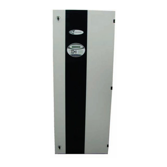
Power-all PS-SP Series User Manual And Instruction Manual (61 pages)
3:3 phase 10 to 60 lVa, 192 Vdc
Brand:
Power-all
| Category:
UPS
| Size: 2 MB
Table of Contents
Gamatronic Electronic Industries Ltd
2
Table of Contents
3
1 Safety Precautions
7
Do's
7
Don'ts
7
2 General Features
8
Figure 1: Schematic Diagram of the Operation of the UPS
8
Major Subsystems
9
Rectifier
9
Batteries
10
Inverter
10
Static Switch
10
Bypass Isolation Transformer (Option)
10
Control System
10
Parallel Operation
9
Advantages of Parallel Operation
9
Control Panel
11
Figure 3: Control Panel on the 40 - 60 Kva Model with Optional Larger Cabinet
11
Figure 2: Control Panel on the 10 Kva to 60 Kva Models
11
Battery Check
12
Communications
12
Ease of Use
12
Event Logs
12
Measurement
12
Power-On Self Tests
12
Real Time
12
Connections
13
Emergency Power-Off (EPO)
13
Service Mode
13
3 Parallel Operation (Option)
14
Centralized Vs. Decentralized Static Switch
14
Decentralized Parallel Mode of Operation
14
Figure 4: Decentralized Parallel Μps - Cable Connections
15
Figure 5: Centralized Parallel Μps - Cable Connections
16
Figure 6: Control Panel on the Standard Cabinet (10Kva to 60Kva Models)
17
Function Buttons on the Standard Cabinet
18
Information Buttons on the Standard Cabinet
18
The Control Panel on the Larger Cabinet
22
4 Control Panel & Indicators
17
The Control Panel on the Standard Cabinet
17
Figure 7: Control Panel on the Larger Cabinet (Optional for 40-60KVA Models)
22
Function Buttons on the Larger Cabinet
23
Information Buttons on the Larger Cabinet
23
Figure 9: Accessing the Log on the Standard Cabinet
27
Figure 8: LOG Messages Structure
27
Figure 10: Accessing the Log on the Large Cabinet
28
Figure 11: Active Current Sharing
32
Figure 12: Voltage Correction
32
LED Indicators
33
The LOG, SET, and HELP Buttons for All Models
27
Table 1: Log Variables
29
System Fault Diagnostics
31
Figure 13: LED Indicators on the Standard Cabinet
33
Figure 14: LED Indicators on the Optional Larger Cabinet
33
Table 2: LED Indicators
34
5 Operating the Μps Series Ups
35
Turning the UPS on
35
Turning the UPS off
36
Activating Maintenance Bypass
37
Deactivating MAINTENANCE BYPASS
38
After Use of the Emergency Power-Off Switch
39
Setting the Real Time Clock
39
6 Communications
40
RS232 Interface
40
Table 3: RS232 Connector Pin Assignment
40
Table 4: LED Indicators on Remote Monitor Panel
42
Connecting the Monitor Box to the UPS
43
The Alarm Interface
41
Remote Monitor Box (Optional)
42
Figure 15: Remote Monitor Box
42
Table 5: Control Buttons on Remote Monitor Panel
43
Table 6: Trouble Shooting and Problem Solving
44
7 Troubleshooting
44
Table 7: PC Board Check Points & Voltage Ranges
46
8 Site Preparation
47
Installation Considerations
47
Electrical Wiring
48
Figure 16: External Circuit Breakers
48
Table 8: External Circuit Breakers - Required Minimum Ratings
49
Table 9: Wiring Requirements
49
Terminal Connections
50
Figure 17: Terminal Connections
50
9 Installation
51
Accessibility
51
Circuit Breakers
51
Figure 18: Circuit Breakers on the 10-20KVA Models
51
Figure 19: Circuit Breakers on the 30-60 Kva Models
52
Figure 20: Connecting the External Battery Cabinet
54
Turning on the UPS for the First Time
55
Installation of Decentralized Parallel Systems
57
Parallel Start-Up
58
Decentralized (2 Upss Only)
58
Installation of Standalone UPS
53
Wiring/Cabling Instructions
53
External Battery Cabinet
54
Table 10: Technical Specifications
60
10 Technical Specifications
60
Advertisement
Advertisement
Related Products
Power-all FRUK19-3000HV-01V
Power-all Categories
UPS
More Power-all Manuals
Login
Sign In
OR
Sign in with Facebook
Sign in with Google
Upload manual
Upload from disk
Upload from URL