Sign In
Upload
Manuals
Brands
Powell Manuals
Controller
FlexTrol Class E2
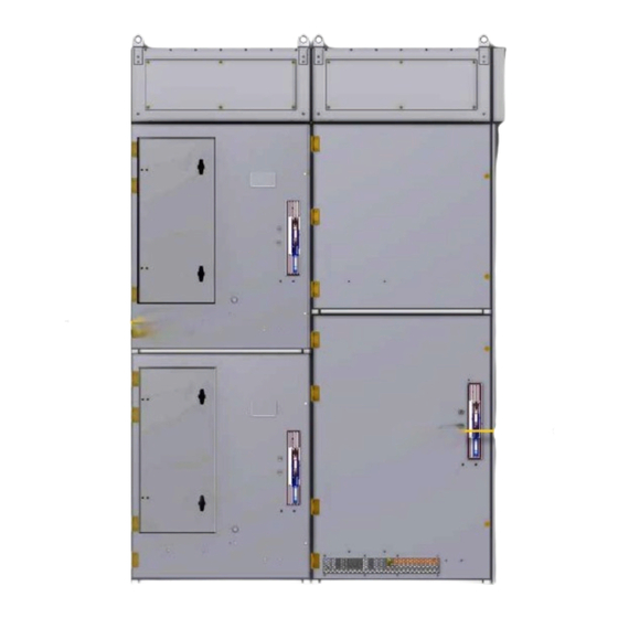
Powell FlexTrol Class E2 Manuals
Manuals and User Guides for Powell FlexTrol Class E2. We have
1
Powell FlexTrol Class E2 manual available for free PDF download: Instruction Bulletin
Powell FlexTrol Class E2 Instruction Bulletin (65 pages)
Medium Voltage Controllers
Brand:
Powell
| Category:
Controller
| Size: 2 MB
Table of Contents
Table of Contents
5
Ch 1 General Information
11
S Cope
12
P Urpose
12
I Nstruction B Ulletins a Vailable E Lectronically
12
Associated B Ulletins
12
Ch 2 Safety
13
S Afe Ork Ondition
13
S Afety G Uidelines
14
G Eneral
14
S Pecific
15
X-R Ays
15
S Afety Abels
16
Ch 3 Equipment Description
17
G Eneral
17
F Lex T Rol ™ C Lass E2 M Edium V Oltage C Ontroller
17
Figure 1 Flextrol™ 400A & 800A
18
Figure 2 Two-High Vertical Section Rear View (400A)
19
Figure 3 High and Low Voltage Compartments
20
Atings
21
Basic I
21
Basic Mpulse Evel
21
D Ielectric T Est
21
M Edium V Oltage C Ontactors
21
Table a Horsepower, Current, and Voltage Ratings
21
Table B Voltage and Interrupting Ratings of Class E2 Medium Voltage Controllers
21
M Anual I Solation Switch
22
Figure 4 Eaton Type SL Medium Voltage Vacuum Contactor 400A
22
Figure 5 Eaton Type SL Medium Voltage Vacuum Contactor 800A
23
M Echanical Nterlocking
24
Figure 6 Isolating Switch Operating Handle
24
Figure 7 Typical Dimensions for Flextrol
25
A Uxiliary Ompartments
26
P Ower F Uses
26
S Tarting Utotransformers or Eactors
27
D Imensions
27
Ch 4 Installation
28
G Eneral
28
R Eceiving
28
S Torage
28
Andling
29
Figure 8 Recommended Method for Lifting an Indoor Lineup
29
Figure 9 Typical Flextrol™ Floor Plans
30
P Ositioning of the E Nclosure
31
R Emoving the M Edium V Oltage V Acuum C Ontactor
31
Removing the Vacuum Contactor from the High Voltage Compartment
31
P Ower Onnections
33
Table C General Guideline for Outgoing Feeder Cables
33
G Rounding
34
Figure 10 Ground Bus Splicing Configuration
35
C Onnections
36
Main B Us Assembly I Nsulation
36
I Ncoming P Ower C Onnections
36
Wrapping Bus Joint
36
Table D Bolt Torque Values for Flextrol
36
Table E Bus Wrapping Components
36
Table F Insulation of Bus Bar
37
Table G Insulation of Single Bus Bar Connection Joint
37
Figure 11 Insulation of Bus Bar
37
Figure 12 Single Bus Bar Connection Joint
37
Table H Insulation of Double Bus Bar Connection Joint
38
Table I Insulation of Tee Connection Joint
38
Applying PVC Boots
39
Cleaning Bus Insulation
39
Figure 15 Dead End Bus Joint Insulation
39
Figure 13 Double Bus Bar Connection Joint
38
Figure 14 Tee Connection Joint
38
Table J Insulation of Dead End Bus Bar Joint
39
Figure 16 Flextrol™ - 400A
40
Figure 17 Flextrol™ - 800A
40
M Otor C Onnections
41
P Ower C Able T Ermination
41
C Ontrol C Ables and C Onnections
42
Figure 18 Low Voltage Compartment
42
Figure 19 Wire Way
42
G Round F Ault C Urrent T
42
I Nsulating P Rimary C Ables
42
M Echanical O Peration C Heck
43
S Urge Rotection
43
S Afety I Nterlocks
44
Isolating Switch Operating Handle
44
Door Interlocks
44
Contactor - Isolating Switch Mechanical Interlock
45
Door Interference
45
Figure 20 Isolation Switch Interlock
45
Ch 5 Operation
46
G Eneral
46
P Reparation of the Ontroller for Peration
46
Cleaning
46
Lubricating
46
Manual Operation
47
Adjustments
47
Pre-Startup Checks
47
Contactor Interlock Pre-Start up Check
47
Est P Ower C Ircuit
48
Figure 21 Mechanical Interlock Verification
48
I -P Ot and M Egger T Est
49
Preparing for the Hi-Pot and Megger Test
49
Performing the Hi-Pot and Megger Test
49
P Re -O Peration T Est
50
S Tart
50
Rocedure
50
Preliminary Checks
50
Setting of Adjustable Protective Devices
51
Medium Voltage Vacuum Contactor Inspection
51
Medium Voltage Vacuum Contactor Testing
51
Isolating Switch Adjustment
51
Power Fuse Inspection
52
Figure 22 Blown Fuse Indicator
52
Table K Eaton Publication References
52
Ch 6 Maintenance
53
Maintenance P Recautions
53
P Reventative Maintenance G Uidelines
53
Ch 7 Recommended Renewal Parts and Replacement Procedures
55
O Rdering I Nstructions
55
R Ecommended R Enewal P Arts
55
Renewal Parts Quantity
55
Eplacement P Rocedures
55
Fuse Removal/Replacement Procedure
56
Auxiliary Contacts Inspection and Replacement
57
R Eplacement P Arts
58
Table L Medium Voltage Vacuum Contactor Eaton 400A SL
58
Table M Medium Voltage Vacuum Contactor Eaton 800A SL
59
Table N R-Rated Clip-On Fuses for 400A Contactor
60
Table O R-Rated Bolt-On Fuses for 800A Contactor
61
Table P E-Rated Clip-On Fuses for 400A Contactor
62
Table Q E-Rated Bolt-On Fuses for 800A Contactor
62
Table R Control Relays
63
Table S Current Transformers
63
Table T Ground Current Transformers
63
Table U Control Power Transformers - SNC
64
Table V Control Power Transformer Primary Fuses
64
Advertisement
Advertisement
Related Products
Powell Ellie Bench
Powell Categories
Indoor Furnishing
Circuit breakers
Industrial Electrical
Switch
Measuring Instruments
More Powell Manuals
Login
Sign In
OR
Sign in with Facebook
Sign in with Google
Upload manual
Upload from disk
Upload from URL