
Summary of Contents for Powell FlexTrol Class E2
- Page 1 DRAFT Powered by Safety ® Instruction Bulletin - 01.4IB.46300 FlexTrol™ Class E2 Medium Voltage Controllers 5kV and 7.2kV - 400A and 800A Motor Control with Eaton Contactors...
- Page 2 FlexTrol™ Class E2 Medium Voltage Controllers with 01.4IB.46300 Eaton Contactor Contact Information Powell Electrical Systems, Inc. powellind.com info@powellind.com Service Division 7232 Airport Blvd Houston, Texas 77061 Tel: 1.800.480.7273 Powered by Safety ®...
- Page 3 01.4IB.46300 Signal Words Qualified Person As stated in ANSI Z535.4-2007, the signal word is For the purposes of this manual, a qualified a word that calls attention to the safety sign and person, as stated in NFPA 70E®, is one who has designates a degree or level of hazard seriousness.
- Page 4 FlexTrol™ Class E2 Medium Voltage Controllers with 01.4IB.46300 Eaton Contactor This page is intentionally left blank. Powered by Safety ®...
-
Page 5: Table Of Contents
01.4IB.46300 Contents Ch 1 General Information ....................1 A. S ................................2 cope B. p ................................2 urpoSe c. I ....................2 nStructIon ulletInS vAIlABle lectronIcAlly D. A ............................2 SSocIAteD ulletInS Ch 2 Safety ........................3 A. S ............................3 onDItIon B. S ...............................4 Afety uIDelIneS c. - Page 6 FlexTrol™ Class E2 Medium Voltage Controllers with 01.4IB.46300 Eaton Contactor Contents l. M ............................31 otor onnectIonS M. p ..........................31 oWer ABle erMInAtIon n. I ..........................32 nSulAtInG rIMAry ABleS o. G ) ..................32 rounD Ault urrent rAnSforMerS hrouGh p.
- Page 7 01.4IB.46300 Contents Ch 7 Recommended Renewal Parts and Replacement Procedures ......45 A. o ............................. 45 rDerInG nStructIonS B. r .......................... 45 ecoMMenDeD eneWAl ArtS 1) Renewal Parts Quantity ...............................45 c. r ..........................45 eplAceMent roceDureS 1) Fuse Removal/Replacement Procedure ...........................46 Auxiliary Contacts Inspection and Replacement ......................47 D.
- Page 8 FlexTrol™ Class E2 Medium Voltage Controllers with 01.4IB.46300 Eaton Contactor Figures Figure 1 FlexTrol™ 400A & 800A ..................8 Figure 2 Two-High Vertical Section Rear View (400A) ..........9 Figure 3 High and Low Voltage Compartments ............10 Figure 4 Eaton Type SL Medium Voltage Vacuum Contactor 400A ......12 Figure 5 Eaton Type SL Medium Voltage Vacuum Contactor 800A ......13 Figure 6...
- Page 9 01.4IB.46300 Tables Table A Horsepower, Current, and Voltage Ratings ............11 Table B Voltage and Interrupting Ratings of Class E2 Medium Voltage Controllers ..11 Table C General Guideline for Outgoing Feeder Cables ..........24 Table D Bolt Torque Values for FlexTrol™ ..................26 Table E Bus Wrapping Components ................26 Table F Insulation of Bus Bar ...................27 Table G Insulation of Single Bus Bar Connection Joint ..........27...
- Page 10 FlexTrol™ Class E2 Medium Voltage Controllers with 01.4IB.46300 Eaton Contactor This page is intentionally left blank. Powered by Safety ®...
-
Page 11: Ch 1 General Information
The information in this instruction bulletin is not intended to explain all details or variations of the Powell equipment, nor to provide for every possible contingency or hazard to be met in connection with installation, testing, operation, and maintenance of the equipment. For additional information and instructions for particular problems, which are not presented sufficiently for the user’s purposes, contact Powell at 1.800.480.7273. -
Page 12: S Cope
Powell equipment. 1. Safety guidelines 2. General descriptions of the operation and For more information visit powellind.com. maintenance of FlexTrol medium voltage To contact the Powell Service Division call controllers 1.800.480.7273, or email 3. Instructions for installation and placing info@powellservice.com. -
Page 13: Ch 2 Safety
01.4IB.46300 Ch 2 Safety N Exception No. 1: An adequately rated permanently mounted test device shall be a. s permitted to be used to verify the absence of onDition voltage of the conductors or circuit parts at The information in Section A is quoted from the work location, provided it meets the all NFPA 70E 2018 - Article 120, 120.5 Establishing an following requirements: (1) It is permanently... -
Page 14: S Afety G Uidelines
FlexTrol™ Class E2 Medium Voltage Controllers with 01.4IB.46300 Eaton Contactor B. s 8. Where the possibility of induced voltages aFety uiDelines or stored electrical energy exists, ground Study this instruction bulletin and all other the phase conductors or circuit parts associated documentation before uncrating before touching them. -
Page 15: S Pecific
DEFORM THE PARTS. DO NOT FORCE CONTACTOR. Before performing work on THE PARTS INTO POSITION. CONTACT a vacuum contactor, remove the vacuum POWELL FOR INSTRUCTIONS. contactor from service and remove it from the Class E2 Medium Voltage Controller. e. x-r 3. -
Page 16: S Afety Abels
FlexTrol™ Class E2 Medium Voltage Controllers with 01.4IB.46300 Eaton Contactor F. s aFety aBels The medium voltage controller has DANGER, WARNING, CAUTION, and instruction labels attached to various locations. All equipment DANGER, WARNING, CAUTION, and instruction labels shall be observed when the medium voltage controller is handled, operated, or maintained. -
Page 17: Ch 3 Equipment Description
For applications other than those indicated, of the equipment. Separate instructions consult Powell. Each controller occupies all covering particular equipment, devices, or or a portion of a steel structure that may also components are not included in this instruction enclose a horizontal bus system to distribute bulletin, but are available upon request. -
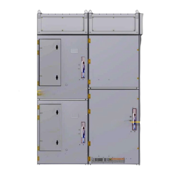
Page 18: Figure 1 Flextrol™ 400A & 800A
FlexTrol™ Class E2 Medium Voltage Controllers with 01.4IB.46300 Eaton Contactor Figure 1 FlexTrol™ 400A & 800A a. 400A Controller b. 800A Controller Powered by Safety ® Equipment Description... -
Page 19: Figure 2 Two-High Vertical Section Rear View (400A)
01.4IB.46300 Starters are available with bolt-in or clip-in Figure 2 Two-High Vertical Section Rear View (400A) main fuses. Contactors may have bolted connections or stab-in connections to the starter cell. The flow of current through a starter with bolted fuses and a stab-in contactor can be described as follows: The line finger assembly mounted at the back of the enclosure serves to connect... -
Page 20: Figure 3 High And Low Voltage Compartments
FlexTrol™ Class E2 Medium Voltage Controllers with 01.4IB.46300 Eaton Contactor Figure 3 High and Low Voltage CAUTION Compartments Control Power may be present in the low voltage compartment. The low voltage compartment shall only be entered with extreme care. a. Surge Arrester b. -
Page 21: Atings
01.4IB.46300 c. r atings Refer to the specific job drawings for the detail ratings applicable to a particular controller. The basic ratings equal or exceed NEMA STD ICS 3, and are summarized in Table A, Horsepower, Current, and Voltage Ratings Table B, Voltage and Interrupting Ratings of Class E2 Medium Voltage Controllers. -
Page 22: M Anual I Solation Switch
FlexTrol™ Class E2 Medium Voltage Controllers with 01.4IB.46300 Eaton Contactor g. M The Eaton Type SL 400A Medium Voltage anual solation witcH vacuum contactor and isolating switch FlexTrol™ follows the NEMA definition and combinations will accommodate the R-Type, contain means for manually isolating the and the E-Type bolt-in fuses as standard and power circuit by operation of a disconnecting clip-mounted hookeye fuses as an option,... -
Page 23: Figure 5 Eaton Type Sl Medium Voltage Vacuum Contactor 800A
01.4IB.46300 Figure 5 Eaton Type SL Medium Voltage CAUTION Vacuum Contactor 800A All power sources must be isolated and locked out before servicing the equipment. For applications where the controller is back fed, the grounding fingers should be removed from the isolation switch. The switch consists of a fixed rear portion and a removable front portion. -
Page 24: M Echanical Nterlocking
FlexTrol™ Class E2 Medium Voltage Controllers with 01.4IB.46300 Eaton Contactor Figure 6 Isolating Switch Operating Handle FlexTrol is manufactured with several built-in interlock provisions and safety features to reduce hazards and provide proper operating sequences: • A mechanical interlock prevents opening the medium voltage door with the switch in the closed position. -
Page 25: Figure 7 Typical Dimensions For Flextrol
01.4IB.46300 Figure 7 Typical Dimensions for FlexTrol™ 107.00 92.00 73.00 46.00 27.00 36.00 36.00 FlexTrol 400A 107.00 92.00 54.00 36.50 36.00 36.00 FlexTrol 800A Note: The drawings in Figure 7 should NOT be used for any construction purposes. For construction information, refer to the specific drawings furnished with the equipment. Powered by Safety ®... -
Page 26: A Uxiliary Ompartments
FlexTrol™ Class E2 Medium Voltage Controllers with 01.4IB.46300 Eaton Contactor i. a An electrical interlock is provided to uxiliary oMpartMents disconnect the control power transformer A variety of enclosure sizes and medium secondary before the isolating switch stabs voltage compartments are furnished in are disconnected from the controller line FlexTrol™... -
Page 27: S Tarting Utotransformers Or Eactors
01.4IB.46300 k. s tarting utotransForMers or eactors Reduced-voltage starters include a reactor or autotransformer designed for starting duty in accordance with NEMA ICS 3. The duty cycle for the medium-duty application is three starts, 30 seconds apart, followed by a one-hour rest. A heavier-duty cycle will cause overheating and possible damage to the reactor or autotransformer. -
Page 28: Ch 4 Installation
Space heaters within the equipment should Note: Any questions regarding equipment be energized, if so equipped. Humidity handling should be referred to Powell. controlling desiccant materials should be utilized when space heaters are not When controllers are received, the purchaser provided or cannot be energized. -
Page 29: Andling
01.4IB.46300 2. Equipment designed for outdoor exposure It is preferable to handle FlexTrol™ with may be stored either in indoor or outdoor overhead cranes, by the lifting means storage locations. The equipment must provided (Figure 8). If bases are furnished, be protected from airborne external the equipment may be moved on an even contaminates if stored outdoors. -
Page 30: Figure 9 Typical Flextrol™ Floor Plans
FlexTrol™ Class E2 Medium Voltage Controllers with 01.4IB.46300 Eaton Contactor Figure 9 Typical FlexTrol™ Floor Plans Mounting Holes Mounting Holes Bottom View SCALE .4 Note: The drawing in Figure 9 should NOT be used for any construction purposes. For construction information, refer to the specific drawings furnished with the equipment. -
Page 31: P Ositioning Of The E Nclosure
01.4IB.46300 e. p F. r ositioning oF tHe nclosure eMoving tHe eDiuM oltage acuuM ontactor To enable proper operation of equipment, CAUTION it is essential to securely fasten the lineups in a true upright position on a smooth, level Do NOT work on a Medium Voltage Controller surface. - Page 32 FlexTrol™ Class E2 Medium Voltage Controllers with 01.4IB.46300 Eaton Contactor ii. OFF Position: When the iv. Disconnect the secondary control switch is in the OFF position circuit plug from the left side of the (Figure 6, d), the isolating switch is in vacuum contactor and stow it so the OPEN position, the high voltage that the cable will not be damaged.
-
Page 33: P Ower Onnections
01.4IB.46300 c. Removing the Vacuum Contactor from ix. If the contactor is being replaced, move the Upper High Voltage Compartment the contactor interlock lever to the new contactor. x. Reverse the procedure to reinstall the CAUTION contactor. xi. Adjust the contactor interlock rod Do NOT work on a Medium Voltage Controller according to the Contactor Interlock vacuum contactor with the control circuit... -
Page 34: G Rounding
FlexTrol™ Class E2 Medium Voltage Controllers with 01.4IB.46300 Eaton Contactor H. g Figure 16 shows the grounding connection rounDing for the 400A controller equipment. Figure 17 Before power connections can be made, the shows the grounding connection for the 800A switchgear vertical sections must be grounded. -
Page 35: Figure 10 Ground Bus Splicing Configuration
01.4IB.46300 2. Join the clean contact surfaces by using the Figure 10 Ground Bus Splicing Configuration hardware provided. The correct length of bolt must be used in each joint to insure that electrical clearances at bolt locations are maintained. As a general rule, when using 1/2"... -
Page 36: C Onnections
FlexTrol™ Class E2 Medium Voltage Controllers with 01.4IB.46300 Eaton Contactor To provide adequate bus joint insulation, use Table D Bolt Torque Values for FlexTrol™ any of the following methods: Bolt Torque Bolt Dimensions Head Ft-Lbs Kg-M • Wrapping bus joints, using tape or heat (inches) shrink material •... -
Page 37: Figure 11 Insulation Of Bus Bar
01.4IB.46300 Figure 11 Insulation of Bus Bar Figure 12 Single Bus Bar Connection Joint .048 (1.2) Approximate Epoxy Insulation Dimension (Tape Tension) Thermoplastic Sleeving 1/2W or Tape Insulation “W” “B” - 1/2 LAP 1 - Layer, 1/2 LAP = 2 Thicknesses “A”... -
Page 38: Figure 13 Double Bus Bar Connection Joint
FlexTrol™ Class E2 Medium Voltage Controllers with 01.4IB.46300 Eaton Contactor Figure 13 Double Bus Bar Connection Joint Figure 14 Tee Connection Joint “C” Epoxy Insulation Thermoplastic Sleeving 4” (101.6) Wide or Tape Insulation PAD HV Tape “C” .50 (12.7) .50 (12.7) “B”... -
Page 39: Applying Pvc Boots
01.4IB.46300 Figure 15 Dead End Bus Joint Insulation Note: The PVC insulation boots are furnished for standard configurations. Pre-Insulation Epoxy Insulation Special configuration conditions may Thermoplastic Sleeving or Tape Insulation require taped joints if PVC boots are Apply RB Putty Sparingly not available. -
Page 40: Figure 16 Flextrol™ - 400A
FlexTrol™ Class E2 Medium Voltage Controllers with 01.4IB.46300 Eaton Contactor Figure 16 FlexTrol™ - 400A Figure 17 FlexTrol™ - 800A a. Isolation Switch and Shutter b. Load Terminals c. Power Fuses d. Ground Connection e. Contactor a. Load Terminals b. Isolation Switch and Shutter c. -
Page 41: M Otor C Onnections
01.4IB.46300 l. M 4. If contact between the cable and an otor onnections adjacent bus cannot be avoided, tape the Motor lead cables may enter or terminate from bus in the immediate vicinity of the cable either the top or the bottom access openings contact point so that the surface creepage of the vertical section. -
Page 42: I Nsulating P Rimary C Ables
FlexTrol™ Class E2 Medium Voltage Controllers with 01.4IB.46300 Eaton Contactor n. i Figure 18 Low Voltage Compartment nsulating riMary aBles All field assembled joints for primary cable terminations should be prepared as outlined under Ch 4 Installation, I. Connections. Upon completion of the cable termination, care must be exercised when taping the exposed termination. -
Page 43: S Urge Rotection
01.4IB.46300 When control conduits enter the unit from Q. s urge rotection below, the conduit should not extend more It is the responsibility of the purchaser to than 1 inch above the floor. The control cables provide suitable surge arresters to protect may be pulled through the conduits before the motor control center from damage due or after the switchgear is installed, whichever... -
Page 44: S Afety I Nterlocks
FlexTrol™ Class E2 Medium Voltage Controllers with 01.4IB.46300 Eaton Contactor in the enclosure immediately above the switch handle. When this contact surface s. s aFety nterlocks of the compartment door depresses the rounded pin, a mechanical catch is released WARNING and allows the isolation switch handle to be moved from one position to another. -
Page 45: Contactor - Isolating Switch Mechanical Interlock
01.4IB.46300 3) Contactor - Isolating Switch Mechanical CAUTION Interlock Defeating the isolating switch interlock allows The isolating switch functions only as a the user to close the isolating switch on to line disconnect and must never close on to stabs. The equipment must be deenergized or interrupt a power load. -
Page 46: Ch 5 Operation
FlexTrol™ Class E2 Medium Voltage Controllers with 01.4IB.46300 Eaton Contactor Ch 5 Operation Inspect the compartment and equipment for loose hardware, wires, and tools that a. g may have been inadvertently left inside the eneral compartment during installation. A test power interlock circuit enables each Clean away dirt and dust, and remove complete unit to be tested without applying packing material which interferes with... -
Page 47: Manual Operation
01.4IB.46300 3) Manual Operation A good vacuum interrupter will withstand a 16kV - 60Hz test or a 23kV -DC test across Operate each device by hand to confirm the normally open contact gap. When that the moving parts operate freely performing DC tests, the voltage should be without binding. -
Page 48: Est P Ower C Ircuit
FlexTrol™ Class E2 Medium Voltage Controllers with 01.4IB.46300 Eaton Contactor Figure 21 Mechanical Interlock Verification d. Verify that the mechanical interlocks between the contactor and handle mechanism are connected and functioning properly. e. The switch drive rod connection (Figure 21, b) and the contactor interlock rod connections (Figure 21, e) -
Page 49: I -P Ot And M Egger T Est
01.4IB.46300 2. For convenience during maintenance c. Install the primary fuses for the when it may be desirable to energize the contactor. contactor or the control circuit only, a d. Remove the required safety grounds. control power test plug is provided. To e. -
Page 50: P Re -O Peration T Est
FlexTrol™ Class E2 Medium Voltage Controllers with 01.4IB.46300 Eaton Contactor Note: If the isolating switch operating Insulation can be tested from phase to phase and from phase to ground. The handle cannot be placed into the ON recommended level for AC Hi-Pot testing is position, deenergize and ground the (2 x V ) volts, where V... -
Page 51: Setting Of Adjustable Protective Devices
01.4IB.46300 • All tools are accounted for. If you 4) Medium Voltage Vacuum Contactor Testing cannot locate a tool, do NOT energize a. Turn the selector switch to the NORMAL the equipment until the tool is found. position. • Settings for protective relays are correct 2) Setting of Adjustable Protective Devices CAUTION Controllers may contain protective devices,... -
Page 52: Power Fuse Inspection
FlexTrol™ Class E2 Medium Voltage Controllers with 01.4IB.46300 Eaton Contactor 6) Power Fuse Inspection Table K Eaton Publication References Storage and Handling 48041 Inspect the condition of all current-limiting Class E2 Medium Voltage Controllers 48041 fuses after every fault current condition. Isolating Switch 400A 48041 Visually inspect the power fuse blown fuse... -
Page 53: Ch 6 Maintenance
If assistance is required for setting up insulators. Voltage failures can result from the proper interval schedule for maintenance, tracking across contaminated insulating contact Powell. surfaces. 2. Check for abrasive material accumulated in the isolating switch mechanism and mechanical interlock bearing and cam surfaces. - Page 54 FlexTrol™ Class E2 Medium Voltage Controllers with 01.4IB.46300 Eaton Contactor 4. Excessive heating can reduce spring tension on the primary connection stabs. Check stab spring tension regularly, especially during excessive heat conditions. 5. Excessive heat can cause the wiring and cable insulation to breakdown.
-
Page 55: Ch 7 Recommended Renewal Parts And Replacement Procedures
The purchaser should determine a. o rDering nstructions which parts and the quantity needed depending on their particular application 1. Order renewal parts from Powell at and the following factors: powellind.com or call 1.800.480.7273. • Amount of time to acquire renewal 2. -
Page 56: Fuse Removal/Replacement Procedure
FlexTrol™ Class E2 Medium Voltage Controllers with 01.4IB.46300 Eaton Contactor iv. Install the two lower flat washers, lock WARNING washers, and nuts. Torque the nuts to 12 ft-lbs. The equipment described in this information v. If the interphase barriers were bulletin contains hazardous voltages and previously removed, ensure they are currents sufficient to cause damage to severe... -
Page 57: Auxiliary Contacts Inspection And Replacement
01.4IB.46300 2) Auxiliary Contacts Inspection and Replacement CAUTION Deenergize the equipment before performing any maintenance work. Failure to do so may result in injury or death to the operating personnel. a. Inspect the auxiliary contacts for wear, scorching or heat damage. Replace any damaged contacts. -
Page 58: R Eplacement P Arts
FlexTrol™ Class E2 Medium Voltage Controllers with 01.4IB.46300 Eaton Contactor D. r eplaceMent arts Table L Medium Voltage Vacuum Contactor Eaton 400A SL Renewal/Replacement Parts Description Part Number 120V Control Three (3) SL Vacuum Bottles 2147A58G02 SL Contactor Control Circuit Board 2147A58G03 SL Contactor Auxiliary Contacts 2NO/2NC 2147A58G04... -
Page 59: Table M Medium Voltage Vacuum Contactor Eaton 800A Sl
01.4IB.46300 Table M Medium Voltage Vacuum Contactor Eaton 800A SL Renewal/Replacement Parts Description Part Number 120V Control Three (3) Vacuum Bottles with Shunt, Support, & Fingers 2147A87G03 Contactor Coils 120VAC (Set of 2) 2147A88G11 240VAC (Set of 2) 2147A88G12 Contactor Tune-Up Kit 2147A99G04 Contactor Miscellaneous Parts Kit 2147A88G15... -
Page 60: Table N R-Rated Clip-On Fuses For 400A Contactor
FlexTrol™ Class E2 Medium Voltage Controllers with 01.4IB.46300 Eaton Contactor Table N R-Rated Clip-On Fuses for 400A Contactor Voltage Rating of 2.4 & 5.5kV “R” Ampere Symmetrical Part Designation Rating Interruption Number 50kA A480R2R-1 50kA A480R3R-1 50kA A480R4R-1 50kA A480R6R-1 50kA A480R9R-1 50kA... -
Page 61: Table O R-Rated Bolt-On Fuses For 800A Contactor
01.4IB.46300 Table O R-Rated Bolt-On Fuses for 800A Contactor Voltage Rating of 2.4 & 5.5kV “R” Ampere Symmetrical Part Designation Rating Interruption Number 50kA A051B1DAR0-2R 50kA A051B1DAR0-3R 50kA A051B1DAR0-4R 50kA A051B1DAR0-6R 50kA A051B1DAR0-9R 50kA A051B1DAR0-12R 50kA A051B2DAR0-18R 50kA A051B1DAR0-19R 50kA A051B2DAR0-24R 50kA A051B2DAR0-32R... -
Page 62: Table P E-Rated Clip-On Fuses For 400A Contactor
FlexTrol™ Class E2 Medium Voltage Controllers with 01.4IB.46300 Eaton Contactor Table P E-Rated Clip-On Fuses for 400A Contactor Voltage Rating of 2.4 & 5.5kV “E” Ampere Symmetrical Part Designation Rating Interruption Number 63kA A055F1D0R0-30E 63kA A055F1D0R0-40E 63kA A055F1D0R0-50E 63kA A055F1D0R0-65E 63kA A055F1D0R0-80E 100E... -
Page 63: Table R Control Relays
01.4IB.46300 Table R Control Relays control Relay - AC Part Number Description 80026-097-01 120VAC, 4-N.O., COIL # TA473V Control Relay - DC Part Number Description 100-C12ZD400 4-N.O., CONTACTS 110VDC Table S Current Transformers Part Number Description 21-101 CT/ITI 100:5A, C10 21-101MR CT/ITI 100:5A, MR 21-151... -
Page 64: Table U Control Power Transformers - Snc
FlexTrol™ Class E2 Medium Voltage Controllers with 01.4IB.46300 Eaton Contactor Table U Control Power Transformers - SNC Part Number Description P21847 1kVA, 2400V-120V P21848 1kVA, 4200V-120V P21850 1kVA, 7200V-120V P21876 1kVA, 2400-120/240V P21877 1kVA, 4200-120/240V P21852 2kVA, 2400V-120V P21853 2kVA, 4200V-120V P21854 2kVA, 7200V-120V Table V Control Power Transformer Primary Fuses... - Page 65 5kV and 7.2kV - 400A and 800A Motor Control With Eaton Contactors March 2019 Powered by Safety ® Powell Electrical Systems, Inc. Tel: 1.800.480.7273 Service Division - Houston powellind.com 7232 Airport Blvd • Houston, TX • 77061 info@powellind.com ©2006 Powell Industries, Inc. • All rights reserved.
Need help?
Do you have a question about the FlexTrol Class E2 and is the answer not in the manual?
Questions and answers