Sign In
Upload
Manuals
Brands
Potter Manuals
Control Panel
PFC-5000 Series
Potter PFC-5000 Series Manuals
Manuals and User Guides for Potter PFC-5000 Series. We have
1
Potter PFC-5000 Series manual available for free PDF download: Installation, Operation And Instruction Manual
Potter PFC-5000 Series Installation, Operation And Instruction Manual (44 pages)
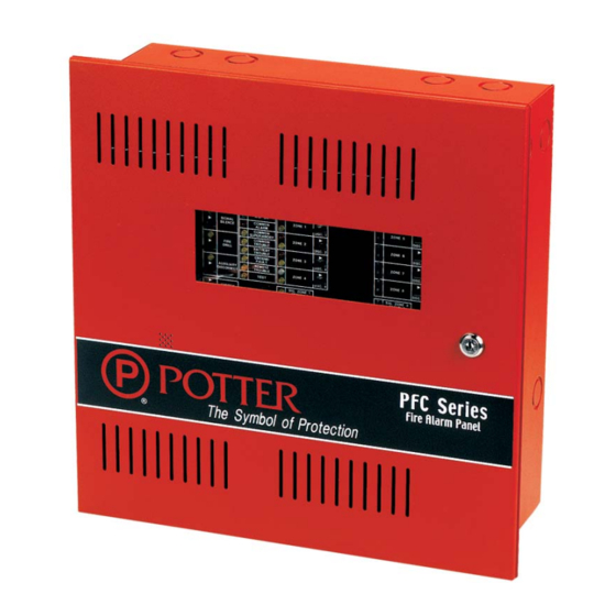
PFC-5000 Series 4 or 8 Zone Fire Alarm Control Panel
Brand:
Potter
| Category:
Control Panel
| Size: 1 MB
Table of Contents
Control Panel
1
Fire Alarm
1
Table of Contents
2
Introduction
5
About this Manual
5
About the PFC-5000
5
Technical Support
5
Document Conventions
6
Circuits and Zones
6
Wiring Styles
6
Circuit Adder Modules
8
Auxiliary Models
8
PFC-5000 Accessories
8
Figure 1: PFC-5002 and PFC-5004 Enclosure Installation and Dimensions
9
Mechanical Installation and Dimensions
9
Figure 2: PFC-5004E Enclosure Installation and Dimensions
10
Figure 3: PFC-5002 and PFC-5004 Module Mounting Locations
11
Modules Mounting Locations
11
Figure 4: PFC-5004E Module Mounting Locations
12
Figure 5: Main Fire Alarm Module
13
Module Settings
13
Main Fire Alarm Module
13
Figure 6: ZA-42 Zone Adder Module
14
Figure 7: ARM-4 or ARM-8 Relay Adder Modle (Zone Operated)
14
Zone Adder Module (Model ZA-42)
14
Relay Modules (Models ARM-4 or ARM-8)
14
Figure 8: UDACT-9100 Dialer Module
15
Figure 9: PR-5100 Polarity Reversal and City Tie Module
15
UDACT / DACT (Model UDACT-9100)
15
Polarity Reversal and City Tie Module (Model: PR-5100)
15
Figure 10: General Field Wiring Considerations
16
Field Wiring
16
General Field Wiring Considerations
16
Figure 11A: Main Fire Alarm Module Terminal Connections
17
Main Fire Alarm Module Terminal Connections
17
Figure 11B: Main Fire Alarm Module Terminal Connections (Cont'D)
18
Figure 12: ZA-42 Zone Adder Module Terminal Connections
19
Figure 12: Zone Adder Module (ZA-42) Terminal Connections
19
Figure 13: Relay Module (ARM-4 or ARM-8) Terminal Connections
20
Figure 14: UDACT-9100 Wiring Diagram
21
UDACT / DACT (UDACT-9100) Terminal Connections
21
Figure 15: PR-510 Polarity Reversal and City Tie Module Terminal Connections
22
Polarity Reversal and City Tie Module (Model:pr-5100) Terminal Connections
22
Figure 16: Power Supply Connections
23
Power Supply Connections
23
Table 1: Wiring Table for Initiating Circuits
24
Table 2: Wiring Table for NAC Circuits
24
Wiring Tables
24
System Checkout
25
Before Turning the Power on
25
Power-Up Procedure
25
Troubleshooting
25
Figure 17: Indicators and Control Location
26
Indicators, Controls, & Operation
26
Indicators
26
Controls
28
Operation
29
Circuit Types
29
Initiating (Detection) Circuit Types
30
Figure 18: Evacuation Codes
31
NAC (Signal) Circuits Types
31
System Confi Guration
32
Main Fire Alarm Board
32
Table 3: Confi Guration DIP Switch Functions on Main Fire Alarm Board
33
ZA-42 Module
34
Table 4: Confi Guration DIP Switch Functions on ZA-42 Module
35
Walk Test Operation
36
Appendix A: Compatible Devices
37
(ULC) Canadian: Two-Wire Smoke Detector Control Panel Compatibility
37
(UL) United States: Two-Wire Smoke Detector Control Panel Compatibility
38
(UL) United States: 4-Wire Smoke Detector Control Panel Compatibility
39
(UL) United States: Signalling Device Control Panel Compatibility
39
Appendix B: Remote Annunciators
40
Appendix C: Module Specifi Cations and Features
41
Appendix C: Module Specifi Cations and Features
43
Appendix D: Power Supply & Battery Calculations
43
Warranty Information
44
Advertisement
Advertisement
Related Products
Potter PFC-5002
Potter PFC-5004
Potter PFC-5004E
Potter PFC-100RC
Potter PFC-6800
Potter PFC-6075
Potter PFC-4064
Potter PFC 2000RC
Potter PFC-3002T
Potter PFC-8500
Potter Categories
Security Sensors
Switch
Control Panel
Security System
Control Unit
More Potter Manuals
Login
Sign In
OR
Sign in with Facebook
Sign in with Google
Upload manual
Upload from disk
Upload from URL