Sign In
Upload
Manuals
Brands
Pneumatech Manuals
Medical Equipment
HTM02-01
Pneumatech HTM02-01 Manuals
Manuals and User Guides for Pneumatech HTM02-01. We have
1
Pneumatech HTM02-01 manual available for free PDF download: Operation And Maintenance Manual
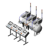
Pneumatech HTM02-01 Operation And Maintenance Manual (93 pages)
Medical Vacuum Plant
Brand:
Pneumatech
| Category:
Medical Equipment
| Size: 30 MB
Table of Contents
Issue Record
4
Introduction
4
AC Input Power Connection
4
WARNINGS, CAUTIONS and NOTES
4
Warnings
4
Cautions
5
Notes
5
Abbreviations Used
5
Scope of this Manual
6
Pneumatech Medical Gas Solutions Service Contact
6
Table of Contents
7
Safety, Storage and Handling
11
Storage
11
Pneumatech Medical Gas Solutions Medical Vacuum Plant Can be Safely Handled and Stored under Normal Working and Environmental Conditions
11
Adverse Environmental Conditions and Harsh Abrasives or Chemicals May Cause Damage to the Unit
11
All Products Are Separately Packaged and Stored under Controlled Conditions
11
Identification
11
Environmental Conditions
11
Figure 1; Identification Label
11
1 Introduction
12
Intended Use
12
Figure 1-1; Medical Vacuum Plant (Modular) - General View
12
2 Technical Specification
13
Table 2-1; Technical Specification
13
3 User Responsibility
14
4 Description of Symbols
14
5 Technical Information
16
Major Components
16
Vacuum Pumps
16
Figure 5-1; Quadruplex Vacuum Plant System Diagram
16
Vacuum Vessel
17
Duplex Filter Assembly
17
6 Installation
18
Environmental Conditions - Installation
18
Component Check
18
7 Commissioning
19
Pre-Test Checks
19
Leak Test
19
Pre-Start-Up Tests
19
Vacuum Pump Testing
20
Commissioning HTM02-01 Medical Vacuum Plant
20
Triplex Pump System
20
Figure 7-1; Pump Control Panel
20
Quadruplex Pump System
21
Pentaplex Pump System
21
Commissioning HTM2022 Medical Vacuum Plant
21
Initial Starting - Vacuum Pumps
21
Proving the Vacuum Pumps
22
Proving the Alarm Circuits
22
Proving the Alarm Interface Indicator Conditions
22
8 Operating Instructions
23
Introduction
23
Pump Controller
23
Interface, Icons and Meny Structure
23
Figure 8-1; Purelogic® Pump Controller
23
Figure 8-2; Purelogic® Pump Controller Icons
24
Table 8-1; Purelogic® Pump Controller
24
Table 8-2; Purelogic® Pump Controller Icons
25
Scrolling through All Screens
26
Figure 8-3; Pump Controller Panel
26
Figure 8-4; Example (Operating Hours)
26
Table 8-3; Purelogic® Pump Controller - Screen Overview
27
Figure 8-5; Purelogic® Pump Controller - Menu Flow
28
Pump Controller Operation
29
Figure 8-6; Pump Controller
29
Table 8-4; Purelogic® Pump Controller - Menu Flow
29
Table 8-5; Pump Controller - Lan/Local Switch
30
Figure 8-7; Example of Running Hours on Display Since Last Service
31
Figure 8-8; Pump Controller - CAN Settings
31
Figure 8-9; Pump Controller - IP Settings
32
Figure 8-10; Pump Controller - Changing the Pressure Unit
33
Figure 8-11; Pump Controller - ARAF
34
Figure 8-12; Pump Controller - Password
35
Central Controller (Purelogic®)
36
Interface, Icons and Menu Structure
36
Figure 8-13; Purelogic® Central Controller
36
Table 8-6; Purelogic® Central Controller
36
Figure 8-14; Central Controller - Main Menu Flowchart (Full Access Situation)
37
Table 8-7; Central Controller - Main Menu Flowchart (Full Access Situation)
37
Table 8-8; Purelogic® Central Controller - Pump
38
Table 8-9; Central Controller - Fault Icons (more Details in Section Plant Fault)
38
Central Controller Operation
39
Figure 8-15; Central Controller - Entering Password
39
Figure 8-16; Central Controller - Testing the Alarms
40
Figure 8-17; Central Controller - CAN Settings
40
Figure 8-18; Central Controller - Setting up the ECO
41
Table 8-10; Central Controller - Other Settings
41
Table 8-11; Central Controller - ECO Slave Settings
43
Figure 8-19; Central Controller - Starting the ECO
44
Figure 8-20; Central Controller - ECO Local
44
Figure 8-21; Central Controller - Isolating a Pump
45
Figure 8-22; Central Controller - Event History
46
Figure 8-23; Central Controller - Information
46
Figure 8-24; Central Controller - Counters
46
Figure 8-25; Central Controller - Inputs and Outputs
47
Figure 8-26; Central Controller - Ethernet
48
Service Menu
49
Figure 8-27; Central Controller - Protections
49
Figure 8-28; Service Menu - Service Icon
49
Figure 8-29; Service Menu - Service Menu Overview
50
Figure 8-30; Service Menu - Service Plan
51
Figure 8-31; Service Menu - Next Service
51
Figure 8-32; Service Menu - History
51
Figure 8-33; Service Menu - Service Maintenance
52
Controller Alarms and Faults
53
Plant Fault
53
Figure 8-34; Controller Alarms and Faults - Plant Fault
53
Figure 8-35; Controller Alarms and Faults - Pumps Commands
54
Table 8-12; Plant Fault
55
Plant Emergency
56
Figure 8-36; Controller Alarms and Faults - Plant Emergency
56
Pressure Fault
57
Medical Vacuum Plant
57
Web Server
58
Figure 8-38; Web Server - USB to LAN Adapter
58
Figure 8-39; Web Server - UTP Cable (CAT 5E)
58
Figure 8-40; Web Server - My Network Places
59
Figure 8-41; Web Server - View Network Connections
59
Figure 8-42; Web Server - Local Area Connection
60
Figure 8-43; Web Server - Properties
60
Figure 8-44; Web Server - Internet Protocol
60
Figure 8-45; Web Server - Internet Explorer
61
Figure 8-46; Web Server - Internet Explorer
62
Figure 8-47; Web Server - Internet Explorer
63
Figure 8-48; Web Server - Proxy Settings
64
Figure 8-49; Web Server - Web Interface
64
Figure 8-50; Web Server - Language Selection
65
Figure 8-51; Web Server - Preferences
65
Figure 8-52; Web Server - Analog Inputs
65
Figure 8-53; Web Server - Counters
66
Figure 8-54; Web Server - Info Status
66
Figure 8-55; Web Server - Digital Inputs
66
Figure 8-56; Web Server - Digital Outputs
66
Figure 8-57; Web Server - Special Protections
67
Figure 8-58; Web Server - Service Plan
67
9 Maintenance
68
Introduction
68
Tools and Equipment
68
Routine Inspection, Checks and Maintenance
68
Cleaning
68
Minimum Requirements
68
Weekly
68
Monthly
68
Six-Monthly
68
Annually
69
Servicing the Bacterial Filters
69
Sterilise the Drain Trap
69
Table 9-1; Inspection and Maintenance Schedule
69
Renew the Filter Element
70
Figure 9-1; Servicing the Bacterial Filters - Drain Tap
70
Figure 9-2; Servicing the Bacterial Filters - Filter Element Renewal
70
Figure 9-3; Central Vacuum Controller - Wiring Diagram
72
Figure 9-4; DOL Vacuum Pump Controller - Wiring Diagram
79
Figure 9-5; YD Vacuum Pump Controller - Wiring Diagram
86
10 Recommended Spares
93
Advertisement
Advertisement
Related Products
Pneumatech HTM2022
Pneumatech Categories
Dryer
Dehumidifier
Security System
Portable Generator
Protection Device
More Pneumatech Manuals
Login
Sign In
OR
Sign in with Facebook
Sign in with Google
Upload manual
Upload from disk
Upload from URL