
Summary of Contents for Pneumatech HTM2022
- Page 1 Medical Vacuum Plant – HTM2022 & HTM02-01 Plant Systems Operation and Maintenance Manual...
- Page 3 Installation, Operation and Maintenance Manual Published by Pneumatech Medical Gas Solutions All possible care has been taken in the preparation of this publication, but Pneumatech Medical Gas Solutions accepts no liability for any inaccuracies that may be found. Pneumatech Medical Gas Solutions reserves the right to make changes without notice both to this publication and to the product which it describes.
-
Page 4: Issue Record
First issue 2015 Introduction This manual contains information needed to install, operate and maintain the Pneumatech Medical Gas Solutions (Pneumatech MGS) vacuum plant. The contents of this manual are intended to be read and used by suitably qualified personnel. AC input power connection Electrical supply requirements vary with different pump models. -
Page 5: Cautions
CAUTION! Use of sub-standard or inappropriate parts and materials may damage the product and invalidate the warranty. Only use genuine Pneumatech Medical Gas Solutions spare parts. CAUTION! Be careful not to over-torque face seal fittings. -
Page 6: Scope Of This Manual
Installation, Operation and Maintenance Manual Scope of this manual This manual describes the Operation Service, Repair and Testing of the Pneumatech MGS Medical Vacuum Plant. Pneumatech Medical Gas Solutions service contact In the event of any queries or problems that cannot be resolved using information in this manual,... -
Page 7: Table Of Contents
Pneumatech Medical Gas Solutions service contact ............iv Safety, Storage and Handling Storage .......................... ix Pneumatech Medical Gas Solutions Medical Vacuum Plant can be safely handled and stored under normal working and environmental conditions........... ix Adverse environmental conditions and harsh abrasives or chemicals may cause damage to the unit. - Page 8 Installation, Operation and Maintenance Manual 7.2 Proving the Alarm Interface Indicator Conditions ........... 20 Operating Instructions 8.1 Introduction ......................21 8.2 Pump controller ..................... 21 8.2.1 Interface, icons and meny structure ................21 8.2.2 Scrolling through all screens ..................24 8.2.3 Pump controller operation ..................
- Page 9 Installation, Operation and Maintenance Manual Figure 8-15; Central controller – entering password ................37 Figure 8-16; Central controller – testing the alarms ................38 Figure 8-17; Central controller – CAN settings ..................38 Figure 8-18; Central controller – setting up the ECO ................39 Figure 8-19;...
- Page 10 Installation, Operation and Maintenance Manual Table 8-4; PureLogic® Pump Controller – menu flow ................27 Table 8-5; Pump controller – LAN/local switch ..................28 Table 8-6; PureLogic® Central Controller ..................... 34 Table 8-7; Central controller – Main Menu flowchart (full access situation) ......... 35 Table 8-8;...
-
Page 11: Safety, Storage And Handling
All products are separately packaged and stored under controlled conditions. Identification The Pneumatech MGS Medical Vacuum Plant is identified by the machine number, printed onto a label located to the side of the control box (see Figure 1-1) and details: •... -
Page 12: Introduction
1 Introduction Intended Use The Pneumatech MGS Medical Vacuum Plant provides a proven and reliable means of generating vacuum in hospitals. The Vacuum Plant is manufactured and tested in accordance with current British Standards and can consist of up to five identical vacuum pumps, one or more vacuum vessels, and duplex bacterial filters. -
Page 13: Technical Specification
Installation, Operation and Maintenance Manual 2 Technical Specification Table 2-1; Technical Specification Product name Physical Characteristics: Height Varies with model Width Varies with model Depth Varies with model Weight Varies with model Environmental Transport, Storage and Operating Conditions: Temperature transport/ storage 5 to 40°C 10 to 40°C Operating conditions: Ventilation should be provided... -
Page 14: User Responsibility
Pneumatech Medical Gas Solutions Service Centre. This device and any of its constituent parts must be repaired only in accordance with written instructions issued by Pneumatech MGS and must not be altered or modified in any way without the written approval or Pneumatech MGS. - Page 15 The CE mark demonstrates that the product conforms to the requirements in the European Council Directive 93/42/EEC concerning medical devices. The number 0088 identifies the notifying body under which the Quality Systems operated within Pneumatech MGS. Consult accompanying documents Connection for the live conductor on permanently installed equipment...
-
Page 16: Technical Information
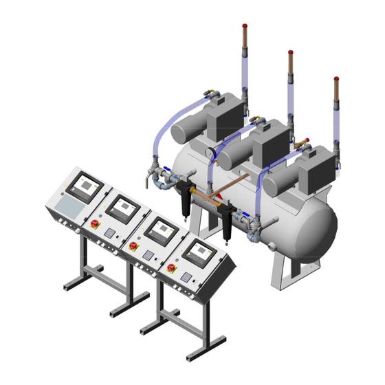
Figure 5-1; Quadruplex Vacuum Plant system diagram Major components Each Pneumatech Medical Vacuum Plant consists of: 1. HTM 2022 - Two or more vacuum pumps, up to a maximum of six, any of which can be selected as Duty pump. -
Page 17: Vacuum Vessel
Installation, Operation and Maintenance Manual 5.1.2 Vacuum vessel One or more vacuum vessels are supplied, manufactured in accordance with BS5169:1992 or BS EN 286-1:1998 and tested to PD5500. Each vessel is provided with a manual drain. 5.1.3 Duplex Filter Assembly •... -
Page 18: Installation
Vessel rating labels are attached to the vacuum vessel(s). Installation 1. Pneumatech MGS Medical Vacuum Plant should be installed within a plant room that provides adequate ventilation with an ambient temperature between +10°C and +40°C. 2. Ventilation should be provided to ensure that the plant room temperature does not exceed an ambient temperature by more than 10°C. -
Page 19: Commissioning
Installation, Operation and Maintenance Manual 7 Commissioning Commissioning is carried out in full: • After initial installation. • After a major component change, and • As part of a planned preventative maintenance programme. The object of commissioning is to ensure that all components are serviceable. Personnel carrying out the following commissioning procedure must be qualified and fully conversant with the information contained in this manual. -
Page 20: Vacuum Pump Testing
Installation, Operation and Maintenance Manual 7.1.3 Vacuum Pump Testing Figure 7-1; Pump Control Panel 1. Switch on the main isolator to pump No.1. 2. Check the rotation and switch off the isolator. 3. Repeat this procedure for the other pump(s). 4. -
Page 21: Quadruplex Pump System
Select the RESET display on each pump controller and all fault conditions should be cancelled. Note: Refer to section 7.2 to complete commissioning of HTM 02-01 Vacuum Plant. 7.1.8 Commissioning HTM2022 Medical Vacuum Plant 7.1.9 Initial Starting – Vacuum Pumps a) Check that the isolating valves between the vacuum pumps and the vacuum receiver are open. -
Page 22: Proving The Vacuum Pumps
Installation, Operation and Maintenance Manual d) If the rotation of any pump is incorrect, isolate the plant at the distribution boards. Get a qualified electrician to check the phases are connected in the correct sequence. If necessary change L1 (red) and L3 (blue). 7.1.10 Proving the Vacuum Pumps a) Once correct rotation has been achieved, switch on both isolators and allow the pumps to... -
Page 23: Operating Instructions
Installation, Operation and Maintenance Manual 8 Operating Instructions Introduction As mentioned in chapter Plant description, both a pump controller per pump is foreseen and a central controller which centrally receives information from the pump controllers and sends commands to those pump controllers. The pump controllers are PureLogic® controllers with text display, while the central controller is a PureLogic®... -
Page 24: Figure 8-2; Purelogic® Pump Controller Icons
Installation, Operation and Maintenance Manual Table 8-1; PureLogic® Pump Controller Item Designation Function Display Shows icons and operating conditioning. Warning LED Is lit when warning is triggered. Service LED Is lit when a service is needed. Operation LED Is lit when the central controller is automatically controlling the pumps and dryers (sequencing is turned on). -
Page 25: Table 8-2; Purelogic® Pump Controller Icons
Installation, Operation and Maintenance Manual Table 8-2; PureLogic® Pump Controller Icons Item Icon Appearance Description Blinking FTGOL fault (the pump failed to go on load) Rotating Running Steady Stopped Steady Under LAN control Blinking Forced local mode Pump cool down, to prevent too many motor starts per hour (maximum is 20 starts/hour) When shown, value must be multiplied by 10 to get the actual value... -
Page 26: Scrolling Through All Screens
Installation, Operation and Maintenance Manual Emergency Stop Service required Blinking Emergency Forced Local mode (triggered by local pressure) Steady Automatic restart after voltage failure Sensor error 8.2.2 Scrolling through all screens Controller panel Figure 8-3; Pump Controller Panel Scroll buttons are used to scroll through all screens. The screens are divided into register screens, measured data screens, digital input screens (numbered as <d. -
Page 27: Table 8-3; Purelogic® Pump Controller - Screen Overview
Installation, Operation and Maintenance Manual The screen shows the screen number <d. 1>, the unit used <hrs> and the related icon (operation). Press Enter key to call up the number of operating hours. Overview of the screens Table 8-3; PureLogic® Pump controller – screen overview Digital input screens Designation <d. -
Page 28: Figure 8-5; Purelogic® Pump Controller - Menu Flow
Installation, Operation and Maintenance Manual Menu flow Figure 8-5; PureLogic® Pump Controller – Menu flow Page 26 Medical Vacuum Plant... -
Page 29: Pump Controller Operation
Installation, Operation and Maintenance Manual Table 8-4; PureLogic® Pump Controller – menu flow Ref. Description Ref. Description Pump inlet pressure Pressure band selection Digital input status Service timer settings Running hours Unit temperature Motor starts Unit pressure Module hours Auto restart function Service timer reading Selection Y-D DOL Actual program version... -
Page 30: Table 8-5; Pump Controller - Lan/Local Switch
Installation, Operation and Maintenance Manual pressed, operation is automatic (based on the pump’s local pressure sensor). When the Off button is active, the pump will not run, unless the JOG function is activated (see Scrolling through all screens). In JOG mode, the pump runs continuously until cancel is pressed. The JOG function is only available in Local Off mode. -
Page 31: Figure 8-7; Example Of Running Hours On Display Since Last Service
Installation, Operation and Maintenance Manual Figure 8-7; Example of running hours on display since last service The number of running hours since the last service is shown. Press Enter (enter your password if it is set) and press Enter again to confirm. The service interval defined in <P. 5> will be subtracted, the blue LED will go out and the service warning will disappear. -
Page 32: Figure 8-9; Pump Controller - Ip Settings
Installation, Operation and Maintenance Manual Figure 8-9; Pump controller – IP settings Changing the temperature unit Scrolling down further till <P. 6> shows the submenu where the temperature unit can be modified. The actually used unit is shown. Possible settings are <˚C> and <˚F>. To change: •... -
Page 33: Figure 8-10; Pump Controller - Changing The Pressure Unit
Installation, Operation and Maintenance Manual Figure 8-10; Pump controller – Changing the pressure unit Automatic restart after voltage failure Submenu <P. 8> makes it possible to (de)activate the Automatic Restart After Voltage Failure (ArAF) function on the level of the local controller. When ArAF is On, a pump in Local mode will restart when the power is reinstated within the selected time frame if it was running before the voltage was interrupted. -
Page 34: Figure 8-11; Pump Controller - Araf
Installation, Operation and Maintenance Manual Figure 8-11; Pump controller – ARAF Password Submenu <P. 11> makes it possible to set a password to protect important settings such as service timer and control mode settings. Attention: Lost passwords can not be recovered. Save the password carefully The following procedure makes it possible to set a password: Page 32 Medical Vacuum Plant... -
Page 35: Figure 8-12; Pump Controller - Password
Installation, Operation and Maintenance Manual Figure 8-12; Pump controller – Password Medical Vacuum Plant Page 55... -
Page 36: Central Controller (Purelogic®)
Installation, Operation and Maintenance Manual Central controller (PureLogic®) 8.3.1 Interface, icons and menu structure Figure 8-13; PureLogic® Central Controller Table 8-6; PureLogic® Central Controller Item Designation Function Display Shows icons and operating conditioning. Warning LED Is lit when warning is triggered. Service LED Is lit when a service is needed. -
Page 37: Figure 8-14; Central Controller - Main Menu Flowchart (Full Access Situation)
Installation, Operation and Maintenance Manual Figure 8-14; Central controller – Main Menu flowchart (full access situation) Table 8-7; Central controller – Main Menu flowchart (full access situation) Ref. Description Ref. Description Normal Pumps Net pressure Commands Menu ECO local Detail Reset Views Select one of the main tabs (Menu - Details or Views) by using the arrow keys (11) followed by... -
Page 38: Table 8-8; Purelogic® Central Controller - Pump
Installation, Operation and Maintenance Manual Table 8-8; PureLogic® Central Controller – Pump Bar Graph Status Description Idle pump The pump is idle and ready to be called. The bar graph is blank. Lead pump The central controller has assigned this pump to the next one to run. -
Page 39: Central Controller Operation
Installation, Operation and Maintenance Manual available to the Purelogic® control algorithm (maximum 20 motor starts /hour). Pump shutdown Pump is in Shutdown condition. Failed to go on load The pressure switch at the pump outlet detects vacuum when it should not. Overload The motor draws too much current and the overload has isolated the pump. -
Page 40: Figure 8-16; Central Controller - Testing The Alarms
Installation, Operation and Maintenance Manual Figure 8-16; Central controller – testing the alarms Menu Test When the test icon is greyed out, the plant needs to be stopped first. Refer to the following paragraphs to stop the ECO system. Setting CAN These settings are set ex factory and need not to be changed. -
Page 41: Figure 8-18; Central Controller - Setting Up The Eco
Pneumatech MGS if it is believed these settings should be changed. Other settings The following settings can be found under the ECO > Master submenu. In normal circumstances they should not be changed. Please contact Pneumatech MGS. Table 8-10; Central controller – other settings Parameter Function Min. - Page 42 Down Delay down. The following settings can be found under the ECO > Slave X submenu. In normal circumstances they should not be changed. Please contact Pneumatech MGS. Page 40 Medical Vacuum Plant...
-
Page 43: Table 8-11; Central Controller - Eco Slave Settings
Installation, Operation and Maintenance Manual Table 8-11; Central controller – ECO slave settings Parameter Function Min. Factory Max. Unit setting setting setting Scheme X To put this pump in a certain priority queue, priority based on the scheme selected (see master parameter “Scheme In Use”... -
Page 44: Figure 8-19; Central Controller - Starting The Eco
Installation, Operation and Maintenance Manual Figure 8-19; Central Controller – Starting the ECO Details Commands Pumps ECO Start Navigate to the Start button and press Enter. A spinning circle on the display should appear to indicate that the ECO system is operating. Stopping and resetting To stop a certain pump, see section Pump controller operation. -
Page 45: Figure 8-21; Central Controller - Isolating A Pump
Installation, Operation and Maintenance Manual The spinning circle symbol will disappear, indicating that the ECO is not active (controlling the pumps) any more. The pumps are now in Forced Local Mode, even though their Local/LAN switch may still be in LAN position. This allows the operator to do maintenance or troubleshooting on the central controller while vacuum is guaranteed by the local pumps. -
Page 46: Figure 8-22; Central Controller - Event History
Installation, Operation and Maintenance Manual Figure 8-22; Central Controller – Event history Viewing information about the central controller Through the following submenu, information regarding MAC address, software, IP settings, etc. can be viewed. Figure 8-23; Central controller – Information Viewing the amount of module hours Through the Counters submenu, the amount of hours that the central controller was powered can be viewed Figure 8-24;... -
Page 47: Figure 8-25; Central Controller - Inputs And Outputs
Installation, Operation and Maintenance Manual of the central controller can be viewed in real time. The configuration of the potential free contact is dual. As such, there is for instance Plant Fault and 2nd Plant Fault. One set of alarms is intended for the BMS ( Building Management System ), the other set is provided with additional resistors and intended to connect to the Zeus 15 Central Alarm System. -
Page 48: Figure 8-26; Central Controller - Ethernet
Installation, Operation and Maintenance Manual Figure 8-26; Central controller – Ethernet Protections menu When there is a problem with one of the direct inputs (see previous paragraph), the red warning LED or blue service LED will be lit. When no problem is visible on the pump overview screen (see Interface icons and menu structure), the Protections submenu must be consulted. -
Page 49: Service Menu
Installation, Operation and Maintenance Manual Figure 8-27; Central controller – Protections 8.3.3 Service menu Menu icon, Service Figure 8-28; Service menu – service icon Function To reset the service plans which are carried out. • To check when the next service plans are to be carried out. •... -
Page 50: Figure 8-29; Service Menu - Service Menu Overview
Installation, Operation and Maintenance Manual Figure 8-29; Service menu – Service menu overview Menu Next service Service History Service plan Running hours Service maintenance Reset Overview Overview Example for Service Plan A: The figure at the left represents the programmed service interval. For Service Plan A, the programmed number of running hours is 2000 hours. -
Page 51: Figure 8-30; Service Menu - Service Plan
Installation, Operation and Maintenance Manual Figure 8-30; Service menu – Service plan Service plan Level Running hours Real time hours Modify Next Service Plan Visualization when the next service intervention needs to be planned. Figure 8-31; Service menu – Next service Next service Level Running hours... -
Page 52: Figure 8-33; Service Menu - Service Maintenance
Installation, Operation and Maintenance Manual Service maintenance Figure 8-33; Service menu – Service maintenance Service maintenance Are you sure? Service function Backup unit in operation Disable plant fault output Deactivate Backup unit in operation Activate Not activated Disable Plant Fault Output •... -
Page 53: Controller Alarms And Faults
Installation, Operation and Maintenance Manual Controller alarms and faults 8.4.1 Controller alarms and faults Different alarms can be transmitted to the hospital control room by means of digital outputs. The configuration of the potential free contacts is dual. As such there is for instance “Plant Fault“ and “2nd Plant Fault”. -
Page 54: Figure 8-35; Controller Alarms And Faults - Pumps Commands
If so, open the cubicle and verify that the CAN cable is correctly connected between the cubicle back plate and the controller. If that is the case, open the CAN connectors and verify that the wires are correctly connected. Contact Pneumatech MGS for further investigation. Page 52... -
Page 55: Table 8-12; Plant Fault
Installation, Operation and Maintenance Manual After fixing the problem, the status should automatically reset. If it doesn’t, press “Local” in the commands screen of the central controller and select ECO “Off” in the ECO menu (see Central controller operation). Then select On again and press Start in the commands menu. Alternatively, in the CAN menu, press CAN Off and On. -
Page 56: Plant Emergency
If no cause can be established, please contact Pneumatech MGS. After fixing the problem, press the Reset button on the overload protection inside the cubicle (see picture), close the cubicle and switch On the isolating switch. -
Page 57: Pressure Fault
Pump by pump, verify if there is an impact on the pressure between the pump running and not running (Contact Pneumatech MGS). If there is no impact, order a non-return valve service kit (consult the spare parts list) and proceed to replacing the non-return valve according to section Non-return valve and inlet screen replacement. -
Page 58: Web Server
Installation, Operation and Maintenance Manual Web server All Purelogic® controllers have a built-in web server that allows direct connection to the company network or to a dedicated PC via a local area network (LAN). This allows to consult certain data and settings via a PC instead of via the display of the controller. -
Page 59: Figure 8-40; Web Server - My Network Places
Installation, Operation and Maintenance Manual Figure 8-40; Web server – My Network places • Click on View Network connections (1). Figure 8-41; Web server – View network connections • Select the Local Area connection (1), which is connected to the controller Medical Vacuum Plant Page 55... -
Page 60: Figure 8-42; Web Server - Local Area Connection
Installation, Operation and Maintenance Manual Figure 8-42; Web server – Local area connection • Click with the right button and select properties (1) Figure 8-43; Web server – Properties • Use the checkbox Internet Protocol (TCP/IP) (1) (see picture). To avoid conflicts, de-select other properties if they are selected. -
Page 61: Figure 8-45; Web Server - Internet Explorer
Installation, Operation and Maintenance Manual • Use the following settings: • IP Address 192.168.100.200 • Subnetmask 255.255.255.0 Click OK and close network connections. Configuration of the web server Configure the web interface The internal web server is designed and tested for Microsoft® Internet Explorer 6, 7 and 8. -
Page 62: Figure 8-46; Web Server - Internet Explorer
Installation, Operation and Maintenance Manual Figure 8-46; Web server – Internet explorer • In the Proxy server Group box, click on the Advanced button (1). Medical Vacuum Plant Page 6... -
Page 63: Figure 8-47; Web Server - Internet Explorer
Installation, Operation and Maintenance Manual Figure 8-47; Web server – Internet explorer • In the Exceptions Group box, enter the IP address of your controller. Multiple IP addresses can be given but they must be separated with semicolons (;). Example: Suppose that you already added two IP addresses (192.168.100.1 and 192.168.100.2). -
Page 64: Figure 8-48; Web Server - Proxy Settings
Installation, Operation and Maintenance Manual Figure 8-48; Web server – Proxy settings Viewing the controller data Open your browser and type the IP address of the controller you want to view in your browser (in this example http://192.168.100.100). The interface opens: Figure 8-49;... -
Page 65: Figure 8-50; Web Server - Language Selection
Installation, Operation and Maintenance Manual Navigation and options • The banner shows the compressor type and the language selector. In this example, three languages are installed on the controller. Figure 8-50; Web server – Language selection • On the left side of the interface you can find the navigation menu (see picture below). If a license for ESi is foreseen, the menu contains 3 buttons. -
Page 66: Figure 8-53; Web Server - Counters
Installation, Operation and Maintenance Manual Figure 8-53; Web server – Counters Info status Machine status is always shown on the web interface. Figure 8-54; Web server – Info status Digital inputs Gives an overview of all Digital inputs and status. Figure 8-55;... -
Page 67: Figure 8-57; Web Server - Special Protections
Installation, Operation and Maintenance Manual Figure 8-57; Web server – Special protections Service plan Shows all levels of the service plan and status. This screen only shows the running hours. It is also possible to show the actual status of the service interval. Figure 8-58;... -
Page 68: Maintenance
Installation, Operation and Maintenance Manual 9 Maintenance Introduction Pneumatech MGS Medical Vacuum plants are designed to operate with the minimum of maintenance, however regular routine minor maintenance operations are recommended to prove the system integrity. Maintenance operations are carried out in accordance with the planned preventative maintenance contract purchased by the customer. -
Page 69: Annually
Installation, Operation and Maintenance Manual 9.3.6 Annually 1. Change bacterial filter elements. 2. Change the oil in each pump. 3. Re-commission the plant to check the performance of each pump and the correct operation of the plant. Table 9-1; Inspection and Maintenance Schedule 5 Yearly Annually Quarterly... -
Page 70: Renew The Filter Element
Installation, Operation and Maintenance Manual Figure 9-1; Servicing the bacterial filters – drain tap 1. Close the drain flask isolation valve (1). 2. Slacken the drain flask (2) to allow atmospheric pressure to be restored in the flask. 3. Unscrew the drain flask and dispose of the liquid safely, in accordance with local regulations. Steam sterilize for 20 minutes at 32 psi at 134°C (+4°C / -0°C). - Page 71 Installation, Operation and Maintenance Manual 12. Position the new element, taking care that the O-ring is in position at the element neck and that the outer foam sock is undamaged. 13. Screw on the element retaining nut, with the O-ring positioned in the retaining nut groove. DO NOT OVERTIGHTEN.
-
Page 72: Figure 9-3; Central Vacuum Controller - Wiring Diagram
Installation, Operation and Maintenance Manual Figure 9-3; Central Vacuum controller – Wiring diagram Medical Vacuum Plant Page 16... - Page 73 Installation, Operation and Maintenance Manual Medical Vacuum Plant Page 55...
- Page 74 Installation, Operation and Maintenance Manual Medical Vacuum Plant Page 18...
- Page 75 Installation, Operation and Maintenance Manual Medical Vacuum Plant Page 55...
- Page 76 Installation, Operation and Maintenance Manual Medical Vacuum Plant Page 20...
- Page 77 Installation, Operation and Maintenance Manual Medical Vacuum Plant Page 55...
- Page 78 Installation, Operation and Maintenance Manual Medical Vacuum Plant Page 22...
-
Page 79: Figure 9-4; Dol Vacuum Pump Controller - Wiring Diagram
Installation, Operation and Maintenance Manual Figure 9-4; DOL Vacuum Pump Controller – Wiring Diagram Medical Vacuum Plant Page 55... - Page 80 Installation, Operation and Maintenance Manual Medical Vacuum Plant Page 24...
- Page 81 Installation, Operation and Maintenance Manual Medical Vacuum Plant Page 55...
- Page 82 Installation, Operation and Maintenance Manual Medical Vacuum Plant Page 26...
- Page 83 Installation, Operation and Maintenance Manual Medical Vacuum Plant Page 55...
- Page 84 Installation, Operation and Maintenance Manual Medical Vacuum Plant Page 28...
- Page 85 Installation, Operation and Maintenance Manual Medical Vacuum Plant Page 55...
-
Page 86: Figure 9-5; Yd Vacuum Pump Controller - Wiring Diagram
Installation, Operation and Maintenance Manual Figure 9-5; YD Vacuum Pump Controller – Wiring diagram Medical Vacuum Plant Page 30... - Page 87 Installation, Operation and Maintenance Manual Medical Vacuum Plant Page 55...
- Page 88 Installation, Operation and Maintenance Manual Medical Vacuum Plant Page 32...
- Page 89 Installation, Operation and Maintenance Manual Medical Vacuum Plant Page 55...
- Page 90 Installation, Operation and Maintenance Manual Medical Vacuum Plant Page 34...
- Page 91 Installation, Operation and Maintenance Manual Medical Vacuum Plant Page 55...
- Page 92 Installation, Operation and Maintenance Manual Medical Vacuum Plant Page 36...
-
Page 93: 10 Recommended Spares
Installation, Operation and Maintenance Manual 10 Recommended Spares For all Service Spares enquiries, contact the Pneumatech MGS Spares Department, giving as much of the following information as possible: Product Part Number: Lot / Batch Number: Approximate date of purchase: This information can be found on the plant rating label which is affixed to the Plant Control Unit.
Need help?
Do you have a question about the HTM2022 and is the answer not in the manual?
Questions and answers