Sign In
Upload
Manuals
Brands
Pine Research Manuals
Industrial Equipment
MSR Series
Pine Research MSR Series Manuals
Manuals and User Guides for Pine Research MSR Series. We have
1
Pine Research MSR Series manual available for free PDF download: User Manual
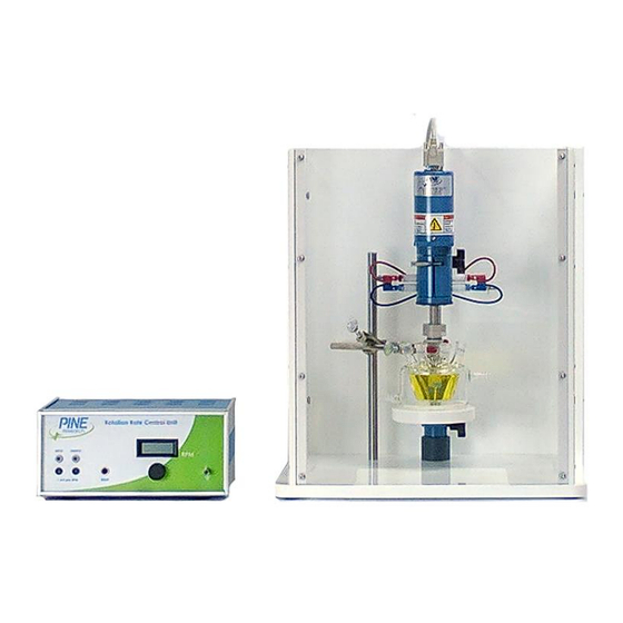
Pine Research MSR Series User Manual (176 pages)
Modulated Speed Rotator
Brand:
Pine Research
| Category:
Industrial Equipment
| Size: 6 MB
Table of Contents
Table of Contents
3
1 Preface
7
Scope
7
Copyright
7
Trademarks
7
Use Limitation
7
Service and Warranty Information
8
Instrument Markings
9
Certifications and Listings
9
Serial Number
9
Model Numbers
9
Specifications
10
Icons (ICônes)
11
Safety Labels (Étiquettes de Sécurité)
14
General Safety Warnings (Avertissements de Sécurité Généraux)
14
Hazardous Material Disclosures
20
2 Description
22
Major System Components
25
Figure 2.1: Major Components of the MSR Rotator System
25
Enclosure Variations
27
Figure 2.2: Two Styles of Enclosure Window
27
Figure 2.3: Three Styles of Anchor Pins
27
Control Unit Components
28
Figure 2.4: Control Unit Front and Back Panels
29
Motor Unit Components
30
Figure 2.5: Motor Unit Components
31
Typical Rotating Disk Electrode Design
32
Figure 2.6: Typical Rotating Disk Electrode (RDE) Tip with Shaft
32
Typical Rotating Ring-Disk Electrode Design
33
Figure 2.7: Typical Rotating Ring-Disk Electrode (RRDE) Tip with Shaft
33
3 Installation
34
Site Preparation
34
Unpacking and Setting up the Rotator
34
4 Operation
39
The Rotating Shaft
39
Figure 4.1: Contact Areas at Top of Rotating Electrode Shafts
39
Figure 4.2: the Brush Chamber (Side View)
40
Installing a Shaft
41
Figure 4.3: Proper (Left) and Improper (Right) Shaft Insertion Positions
44
Figure 4.4: Installing a Tip on to a Shaft
45
Changing the Tip on a Shaft
46
Figure 4.5: Properly Supported and Clamped Electrochemical Cells
49
Mounting the Cell
50
The Enclosure
52
Figure 4.6: Enclosure Properly Mounted on All Four Pins
52
Cell Connections
53
Figure 4.7: Connection of Counter and Reference Electrodes
53
Figure 4.8: Brush Connections for a Rotating Disk Electrode (RDE) or a Rotating Cylinder Electrode (RCE)
54
RDE and RCE Wiring
54
RRDE Wiring
55
Figure 4.9: Brush Connections for a Rotating Ring-Disk Electrode (RRDE)
56
Figure 4.10: Stackable Banana Connector with Optional Stud Connector
57
Figure 4.11: Routing Cables out of the Enclosure
57
Routing Cables and Tubing
57
Proper Grounding
58
Terminology
58
The Earth Ground Connection
58
A Typical Grounding Strategy
59
Figure 4.12: Connect Metal Objects to Earth Ground on Control Box Front Panel
60
Figure 4.13: Connect Potentiostat to Earth Ground on Control Box Front Panel
61
Using the Rotator in a Glove Box
62
Figure 4.14: Glove Box Configuration
62
Rotation Rate Control
63
Manual Control of Rotation
63
Monitoring the Rotation Rate
63
External Control of the Rotation Rate
64
Figure 4.15: Connecting the Rotation Rate Control Cable
64
External Motor Stop Control
65
Circuit Protection
66
5 Electrodes
67
Electrode Handling Precautions
67
Shafts
71
RDE Tips
74
Single-Piece RDE Designs
80
RRDE Tips
82
MM OD RCE Tips
86
MM OD RCE Tips
87
6 Maintenance
88
Routine Cleaning
88
Brush Replacement
88
Internal Brush Replacement
88
Complete Brush Assembly Replacement
91
Lower Bearing Replacement
92
Removing the Motor-Coupling Assembly
93
Installing a New Motor-Coupling Assembly
97
Motor Control Cable Wiring
100
Figure 6.1: Rotator Calibration Toolkit (Including Simple Handheld Tachometer)
101
Figure 6.2: Professional Optical Tachometer with Traceable Calibration
101
Figure 6.3: Use of Optical Tachometer with Reflective Target
101
Rotation Rate Calibration
102
Changing the Input Rotation Rate Ratio
112
Changing the Motor Stop Signal Logic
114
7 Parts and Accessories
118
Mechanical Parts and Hardware
118
Power Cords
121
Figure 7.1: Standard C18 Connection on Power Entry Module
121
Power Supplies
124
Figure 7.2: Location of High Voltage Power Entry and Internal Power Supplies
124
Figure 7.3: Replacement Internal Power Supplies
125
8 Troubleshooting
127
9 Storage and Shipment
131
10 Theory
132
Forced Convection
132
Half Reactions
133
Voltammetry
134
Figure 10.1: Response to a Potential Sweep (Cathodic) from a Solution Initially Containing Only the Oxidized Form (O) with no Reduced Form (R)
136
Figure 10.2: Response to a Potential Sweep (Anodic) from a Solution Initially Containing Only the Reduced Form (R) with no Oxidized Form (O)
137
Voltammogram Plotting Conventions
137
Figure 10.3: a Voltammogram Is a Plot of Current Versus Potential
138
Figure 10.4: Two Popular Voltammogram Plotting Conventions
138
Measuring Limiting Currents
139
Figure 10.5: Sloping Backgrounds in Voltammograms
140
Figure 10.6: Voltammogram for a Solution Containing both O and R
140
Rotating Disk Electrode (RDE) Theory
141
Levich Study
142
Figure 10.7: Levich Study - Voltammograms at Various Rotation Rates
143
Figure 10.8: Levich Study - Limiting Current Versus Rotation Rate
143
Koutecky-Levich Analysis
144
Figure 10.9: Koutecky Levich Study - Voltammograms with Sluggish Kinetics
144
Rotating Ring-Disk Electrode (RRDE) Theory
146
Theoretical Computation of the Collection Efficiency
146
Figure 10.10: Rotating Ring-Disk Voltammograms at Various Rotation Rates
147
Empirical Measurement of the Collection Efficiency
148
Generator/Collector Experiments
149
Comparing Two Competing Pathways
150
Rotating Cylinder Electrode (RCE) Theory
151
References
152
11 Glossary
156
Advertisement
Advertisement
Related Products
Pine Research MSR 636A
Pine Research MSR 710A
Pine Research Categories
Industrial Equipment
More Pine Research Manuals
Login
Sign In
OR
Sign in with Facebook
Sign in with Google
Upload manual
Upload from disk
Upload from URL