Table of Contents
Advertisement
Modulated Speed Rotator (MSR)
User Guide
Pine Research Instrumentation, Inc.
2741 Campus Walk Avenue, Building 100
Durham, NC 27705
USA
http://www.pineresearch.com
Phone: +1(919) 782-8320
Fax: +1 (919) 782-8323
Copyright © 2013-2017 Pine Research Instrumentation, Inc. All Rights Reserved.
DRU10002 (REV 004 / JAN 2017)
Advertisement
Table of Contents

Summary of Contents for Pine Research MSR Series
- Page 1 Modulated Speed Rotator (MSR) User Guide Pine Research Instrumentation, Inc. 2741 Campus Walk Avenue, Building 100 Durham, NC 27705 http://www.pineresearch.com Phone: +1(919) 782-8320 Fax: +1 (919) 782-8323 Copyright © 2013-2017 Pine Research Instrumentation, Inc. All Rights Reserved. DRU10002 (REV 004 / JAN 2017)
-
Page 3: Table Of Contents
Table of Contents Preface Scope Copyright Trademarks Use Limitation Service and Warranty Information Instrument Markings 1.6.1 Certifications and Listings 1.6.2 Serial Number 1.6.3 Model Numbers Specifications Icons (Icônes) Safety Labels (Étiquettes de sécurité) 1.10 General Safety Warnings (Avertissements de sécurité généraux) 1.11 Hazardous Material Disclosures Description... - Page 4 4.7.4 External Motor Stop Control Circuit Protection Electrodes Electrode Handling Precautions Shafts RDE Tips Single-Piece RDE Designs RRDE Tips 15 mm OD RCE Tips 12 mm OD RCE Tips Maintenance Routine Cleaning Brush Replacement 6.2.1 Internal Brush Replacement 6.2.2 Complete Brush Assembly Replacement Lower Bearing Replacement Removing the Motor-Coupling Assembly Installing a New Motor-Coupling Assembly...
- Page 5 Table of Figures Figure 2.1: Major Components of the MSR Rotator System ..........19 Figure 2.2: Two Styles of Enclosure Window ................. 21 Figure 2.3: Three Styles of Anchor Pins .................. 21 Figure 2.4: Control Unit Front and Back Panels ..............23 Figure 2.5: Motor Unit Components ..................
- Page 6 DRU10002 (REV 004 / JAN 2017)
-
Page 7: Preface
Pine Research Instrumentation provides online support for the rotator at the following URL: www.pineresearch.com/shop/rotators/standard/msr/ Copyright... -
Page 8: Service And Warranty Information
The Pine MSR Rotator (Pine part number AFMSRCE, hereafter referred to as “WARRANTED INSTRUMENT”) offered by Pine Research Instrumentation, Inc. (hereafter referred to as “SUPPLIER”) is warranted to be free from defects in material and workmanship for a one (1) year period from the date of shipment to the original purchaser (hereafter referred to as the "CUSTOMER") if used under... -
Page 9: Instrument Markings
Instrument Markings Labels on the control unit and motor unit bear information to identify the MSR rotator and to indicate any certifications or independent testing agency marks which pertain to the instrument (see Figure 2.4). 1.6.1 Certifications and Listings The MSR rotator complies with one or more EU directives and bears the CE marking. -
Page 10: Specifications
Specifications All specifications are subject to change without notice. Power 100 - 240 VAC, +/-10%; 50/60 Hz; 2A Shipping Information shipping weight: 60 pounds (27 kg) shipping dimensions: 24.0 x 24.0 x 24.0 in (61 x 61 x 61 cm) Dimensions control unit: 11.4 x 10.1 x 5.75 in (29 x 26 x 15 cm) -
Page 11: Icons (Icônes)
Icons (Icônes) Special icons (see Tables 1.2, 1.3, and 1.4) are used to call attention to safety warnings and other useful information found in this document. Des icônes spéciales (voir tableau 1.2, 1.3 et 1.4) sont utilisées pour attirer l’attention sur des avertissements de sécurité et autres renseignements utiles disponibles dans ce document. - Page 12 WARNING: Indicates information needed to prevent injury or death to a person or to prevent damage to equipment. AVERTISSEMENT: Indique les informations nécessaires à la prévention de blessures corporelles ou de mort d’un individu ou à la prévention des dommages aux équipements. ROTATING SHAFT HAZARD: Indicates information needed to prevent injury or death to a person due to a high speed rotating shaft.
- Page 13 CAUTION: Indicates information needed to prevent damage to equipment. ATTENTION: Indique les informations nécessaires à la prévention des dommages aux équipements. RISK OF ELECTROSTATIC DAMAGE: Indicates information needed to prevent damage to equipment due to electrostatic discharge. RISQUE DE DOMMAGES ÉLECTROSTATIQUES: Indique les informations nécessaires à...
-
Page 14: Safety Labels (Étiquettes De Sécurité)
Safety Labels (Étiquettes de sécurité) The following specific safety warnings are found on labels attached to the motor unit and on the back panel of the control unit. Les avertissements de sécurité spécifiques suivants se trouvent sur les étiquettes apposées sur le bloc moteur et sur le panneau arrière de l’unité de commande. 1.10 General Safety Warnings (Avertissements de sécurité... - Page 15 WARNING: Risk of electric shock. Disconnect all power before servicing the rotator. AVERTISSEMENT: Risque de décharge électrique. Déconnectez toutes les sources d’alimentation avant de procéder à l’entretien du rotateur. WARNING: Rotating shaft. Do not turn on the rotator or rotate the electrode shaft unless the enclosure window is secured to all four pins as shown below.
- Page 16 CAUTION: Do not exceed the maximum rotation rate for an electrode. Each type of rotating electrode has a specific maximum rotation rate limitation. Consult the documentation for the specific electrode being used in order to learn the maximum rotation rate for that electrode.
- Page 17 WARNING: Do not turn on the rotator or rotate the electrode shaft if the shaft is not securely mounted in the motor coupling. Inspect the shaft to be certain that it is securely mounted. AVERTISSEMENT: Ne mettez pas le rotateur en marche ni l’arbre de l’électrode en rotation si l’arbre n’est pas correctement raccordé...
- Page 18 WARNING: Do not use an electrode shaft which appears to wobble, vibrate, or tilt away from the axis of rotation while rotating. Such a shaft is either improperly installed or physically damaged. Turn off the rotator, disconnect electrical power, and remove the shaft immediately.
- Page 19 CAUTION: When raising or lowering the motor unit along the main support rod, be sure to hold the motor unit carefully so that it does not unexpectedly fall and break the glass cell located below the motor unit. ATTENTION: Lorsque vous montez ou descendez le bloc moteur le long de la barre principale, veillez à...
-
Page 20: Hazardous Material Disclosures
1.11 Hazardous Material Disclosures The information provided in Table 1.5 and Table 1.6 is provided in accordance with Chinese Standard SJ/T 11364, Marking for the Restricted Use of Hazardous Substances in Electronic and Electrical Products. Hazardous Material Disclosure Table AFMSRwxyz Hazardous Substances Lead Mercury Cadmium... - Page 21 有害物质披露表 AFMSRwxyz 有害物质 部件名称 汞 铅 镉 六价铬 多溴联苯 多溴二苯醚 (Pb) (Hg) (Cd) (Cr (VI)) (PBB) (PBDE) 主电路板 供电电路板 液晶显示器 本表格依据 SJ/T 11364 的规定编制 。 O:表示该有害物质在该部件所有均质材料中的含量均在 GB/T 26572 规定的限量要求以下 。 X:表示该有害物质至少在该部件的某一均质材料中的含量超出 GB/T 26572 规定的限量要求。 注: 该部件的制造日期可能会按照以下格式出现在序列号码中: wwyynn:ww 表示周数; yy 表示年的最后两位数; nn 是该周序列号 、每周都从01开始 。 注:...
-
Page 22: Description
2 Description The MSR rotator provides excellent steady-state control of constant rotation rates, but it also offers outstanding acceleration/deceleration control for those applications where the rotation rate must be modulated. The base rotation rate (for steady-state constant rate control) may be manually adjusted from 50 to 10,000 RPM by turning a ten-turn potentiometer knob located on the front panel of the control unit. - Page 23 The motor unit can be positioned vertically along a center post that is mounted in a sturdy and chemically resistant enclosure base. A flat cell platform can also be positioned along the center post, making it easy to raise and lower the cell with respect to the motor unit.
- Page 24 window can be removed to set up the cell, but the enclosure window must be securely mounted to the enclosure base before rotating the electrode. The rotator may be used with rotating disk electrodes (RDEs), rotating ring-disk electrodes (RRDEs), and rotating cylinder electrodes (RCEs). Connections to the rotating electrode shaft are made by two pairs of silver-carbon brushes.
-
Page 25: Major System Components
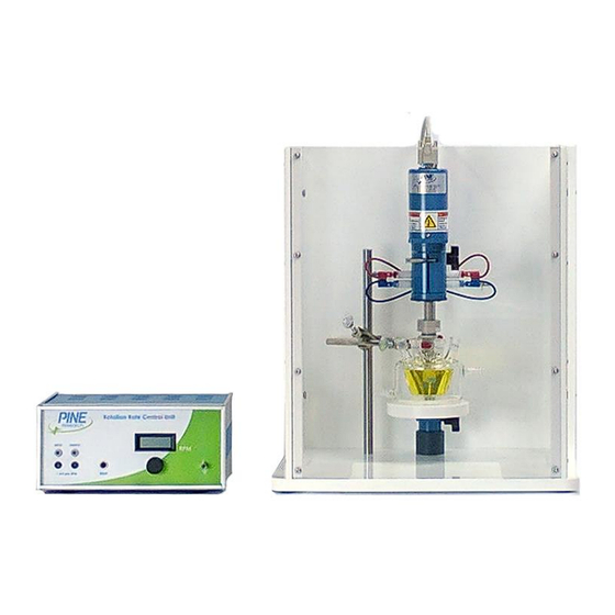
Major System Components The table and photo below (see Figure 2.1) show the major system components. Figure 2.1: Major Components of the MSR Rotator System DRU10002 (REV 004 / JAN 2017) - Page 26 The cell platform, support collar, and motor Center Post unit are supported by the center post. The motor unit is mounted on the center post Motor Unit and holds the motor and brushes. The cell platform supports cells with flat Cell Platform bottom surfaces.
-
Page 27: Enclosure Variations
Enclosure Variations The enclosure consists of the enclosure base (fabricated from an opaque white polymer) and an enclosure window (transparent). The enclosure window may be a single pane (see Figure 2.2, left) or it may be assembled from three separate panes (see Figure 2.2, right). -
Page 28: Control Unit Components
Control Unit Components The table and photo below (see Figure 2.4) show the control unit components. The control unit contains the power supply Control Unit and rotation rate control circuitry. Rotation Rate Display 4 ½ digit display of rotation rate (RPM) Rotation Rate Knob 10 turn knob for manual rotation rate control This connection to the control unit chassis... -
Page 29: Figure 2.4: Control Unit Front And Back Panels
Figure 2.4: Control Unit Front and Back Panels DRU10002 (REV 004 / JAN 2017) -
Page 30: Motor Unit Components
Motor Unit Components The table below and the photographs on the next page (see Figure 2.5) identify the major components of the motor unit. Motor Cable Connector Accepts one end of motor control cable These upper brushes make contact on opposing sides of the rotating shaft and are Upper Brush Pair (red) used to make contact with rotating disk... -
Page 31: Figure 2.5: Motor Unit Components
Figure 2.5: Motor Unit Components DRU10002 (REV 004 / JAN 2017) -
Page 32: Typical Rotating Disk Electrode Design
Typical Rotating Disk Electrode Design Most rotating disk electrodes consist of two parts (see Figure 2.6), a shaft and a tip, but in some cases the entire electrode may be a single piece. Figure 2.6: Typical Rotating Disk Electrode (RDE) Tip with Shaft This insulating shroud material is typically a Insulating Shroud on Tip polymer such as PTFE, PEEK or PCTFE. -
Page 33: Typical Rotating Ring-Disk Electrode Design
Typical Rotating Ring-Disk Electrode Design Rotating ring-disk electrode tips mount on to a special two-conductor shaft (see Figure 2.7). In some cases, the tip can be taken apart into smaller pieces. Figure 2.7: Typical Rotating Ring-Disk Electrode (RRDE) Tip with Shaft This insulating shroud material is typically a Insulating Shroud on Tip polymer such as PTFE, PEEK or PCTFE. -
Page 34: Installation
3 Installation Site Preparation The rotator system should be located on a sturdy table or laboratory bench with ample clearance around the perimeter of the rotator enclosure. The front of the rotator should be unobstructed, and there should be at least 20 cm clearance on each side and behind the rotator, for a total table space of 40 cm x 60 cm. - Page 35 Locate the small bag of hardware. Remove the four pins and four screws. Place each screw in one of the pre-drilled holes along the side walls of the enclosure, two on the left and two on the right. Install the pins onto the screws.
- Page 36 There are several holes in the floor of the enclosure base (4), which are threaded to accept the side post (6). Choose one of these holes and install the side post in it. Then, mount the laboratory clamp on to the side post.
- Page 37 CAUTION: The connectors on both ends of the motor control cable MUST be firmly secured by tightening the pair of screws on each connector. Failure to secure the connectors will result in improper control of the rotation rate. ATTENTION: Les connecteurs situés aux deux extrémités du câble de commande du moteur DOIVENT être fermement attachés en serrant les deux vis de chaque connecteur.
- Page 38 CAUTION: A detachable main power cord is provided with the rotator. Do not replace this cord with an inadequately rated cord. ATTENTION: Un cordon d'alimentation amovible est fourni avec le rotateur. Ne remplace pas ce cordon par un cordon de calibre inadéquat.
-
Page 39: Operation
4 Operation This section of the manual discusses information pertaining to routine operation of the rotator. Users of the rotator should be familiar with all of the information in this section prior to operating the rotator. The Rotating Shaft The electrode shaft normally rotates in a clockwise direction as viewed from the top of the rotator. -
Page 40: Figure 4.2: The Brush Chamber (Side View)
The uppermost portion of the shaft is used to mount the shaft into the rotator (see Figure 4.1). This mounting area is electrically isolated from the remainder of the shaft so that the electrode connections remain isolated from the rotator chassis. An insulating spacer just below the mounting area isolates the mounting area from the electrode contact area. -
Page 41: Installing A Shaft
4.1.1 Installing a Shaft WARNING: Rotating shaft. Entanglement hazard. Turn off the power to the rotator and disconnect the power cord from the power source before installing or removing the electrode shaft or before installing or removing an electrode tip on the end of the shaft. - Page 42 Invert the orientation of the motor unit so that it is upside-down as shown. Loosen the latch on the clamshell doors. Open the doors to provide access to the brush chamber. If there is a shaft already installed, use the hex driver tool (5/64", provided) to loosen the two screws on the motor coupling.
- Page 43 Install the shaft by sliding it through the hole in the lower bearing assembly and into the brush chamber. The shaft should be pushed as far as possible into the motor coupling so that the contact brushes are properly aligned with the electrical contact areas on the rotating electrode shaft (see Figure 4.3).
-
Page 44: Figure 4.3: Proper (Left) And Improper (Right) Shaft Insertion Positions
Figure 4.3: Proper (left) and Improper (right) Shaft Insertion Positions WARNING: Do not turn on the rotator or rotate the electrode shaft if the shaft is not securely mounted in the motor coupling. Inspect the shaft to be certain that it is securely mounted. AVERTISSEMENT: Ne mettez pas le rotateur en marche ni l’arbre de l’électrode en rotation si l’arbre n’est pas correctement raccordé... -
Page 45: Figure 4.4: Installing A Tip On To A Shaft
WARNING: Do not use an electrode shaft which appears to wobble, vibrate, or tilt away from the axis of rotation while rotating. Such a shaft is either improperly installed or physically damaged. Turn off the rotator, disconnect electrical power, and remove the shaft immediately. -
Page 46: Changing The Tip On A Shaft
4.1.2 Changing the Tip on a Shaft WARNING: Rotating shaft. Entanglement hazard. Turn off the power to the rotator and disconnect the power cord from the power source before installing or removing the electrode shaft or before installing or removing an electrode tip on the end of the shaft. - Page 47 WARNING: Do not use or attempt to rotate an electrode tip that has been dropped or otherwise physically damaged. Inspect the electrode tip to be certain that it is not damaged. AVERTISSEMENT: N’utilisez pas et ne tentez pas de mettre en rotation un embout d’électrode qui est tombée ou a été...
- Page 48 CAUTION: Before reconnecting the rotator power cable or the motor control cable to the control unit, be sure the control unit power switch is off and the rotation rate knob is turned to the fully counterclockwise position. ATTENTION: Avant de reconnecter le câble d’alimentation du rotateur ou le câble de commande du moteur à...
-
Page 49: Figure 4.5: Properly Supported And Clamped Electrochemical Cells
WARNING: Do not use an electrode tip which appears to wobble, vibrate, or tilt away from the axis of rotation while rotating. Such an electrode tip is either improperly installed or physically damaged. Turn off the rotator, disconnect electrical power, and remove the electrode tip immediately. -
Page 50: Mounting The Cell
Mounting the Cell All cells should be clamped to the side post and also supported from below using the cell platform. For a cell with multiple side ports, carefully orient the cell so that any accessories mounted in the side ports have enough clearance. Smaller cells may be clamped using a traditional laboratory clamp secured to the center port (see Figure 4.5, left). - Page 51 CAUTION: Center the rotating electrode within the opening on the cell so that it does not rub against the walls of the opening. Damage will occur if the rotating shaft or tip abrades against these walls. ATTENTION: Centrez l’électrode rotative dans l’ouverture de la cellule pour qu’elle ne frotte pas les bords de l’ouverture.
-
Page 52: The Enclosure
The Enclosure WARNING: Rotating shaft. Do not turn on the rotator or rotate the electrode shaft unless the enclosure window is secured to all four pins as shown below. Use extreme caution when operating the rotator at rotation rates above 2000 RPM. AVERTISSEMENT: Arbre en rotation. -
Page 53: Cell Connections
Cell Connections The counter electrode and the reference electrode are usually mounted in appropriate side ports on the electrochemical cell (see Figure 4.7). The counter electrode is often a simple platinum wire or carbon rod to which an alligator clip is easily affixed. -
Page 54: Rde And Rce Wiring
Tip: There is no universally accepted color coding scheme for marking potentiostat cell cable connections. If you are using the rotator with a third-party potentiostat, consult the potentiostat documentation for information about the cell cable markings. 4.4.1 RDE and RCE Wiring There are two pairs of brushes which provide electrical contact with the rotating shaft (see Figure 4.8). -
Page 55: Rrde Wiring
Tip: Most modern potentiostats provide separate cable connections for the working electrode “drive” line and for the working electrode “sense” line. The drive line carries current while the sense line measures the potential. Both of these lines must be connected to the rotating electrode brushes. -
Page 56: Figure 4.9: Brush Connections For A Rotating Ring-Disk Electrode (Rrde)
Tip: It is possible that the brush assemblies on a rotator that has been in use for some time may have been replaced or swapped, and thus, the colors of the brushes may not be as described in the previous paragraph or as shown in Figure 4.9. -
Page 57: Routing Cables And Tubing
Note: Older Pine bipotentiostats use only one cable for both the “drive” and the “sense” signals. The YELLOW connection corresponds to the disk, and the BLUE connection corresponds to the ring. Figure 4.10: Stackable Banana Connector with Optional Stud Connector The jumper cables used to short the opposing brushes feature stackable banana plugs. -
Page 58: Proper Grounding
the bottom of the window that provide clearance for routing cell cables and any tubing out of the enclosure. If required, cables and tubing may be routed through the back panel by drilling small holes in the panel. Any such drilled holes should have a diameter no greater than 13.0 mm (0.5 in). -
Page 59: A Typical Grounding Strategy
the laboratory (via the “third prong”) offers a robust connection to the earth, then this front panel connection can be used as an earth grounding point. It is also very important to note that the chassis of the rotator control unit is in direct contact with the earth ground connector. -
Page 60: Figure 4.12: Connect Metal Objects To Earth Ground On Control Box Front Panel
may act as a source of environmental noise in the measured signals from the electrochemical cell. A simple banana cable with an alligator clip may be used to connect these metal objects to the earth ground. Figure 4.12: Connect Metal Objects to Earth Ground on Control Box Front Panel The second important connection that is frequently (but not always) necessary is to connect the potentiostat to the earth ground (see Figure 4.13). -
Page 61: Figure 4.13: Connect Potentiostat To Earth Ground On Control Box Front Panel
Figure 4.13: Connect Potentiostat to Earth Ground on Control Box Front Panel If the potentiostat offers a chassis terminal connection (often located on the back panel of the potentiostat), then connecting this chassis terminal to the earth ground on the rotator control box may (or may not) reduce or eliminate noise in the measured electrochemical signals. -
Page 62: Using The Rotator In A Glove Box
Using the Rotator in a Glove Box The rotator may be placed in a glove box when working with air or moisture sensitive compounds. A smaller base (sold separately) is available for use in a glove box (see Figure 4.14). It is important to understand that the low humidity environment found in most glove boxes increases the rate of... -
Page 63: Rotation Rate Control
Rotation Rate Control CAUTION: Always turn rotation rate control knob completely counterclockwise (towards the zero rotation rate position) before turning on the rotator. ATTENTION: Tournez toujours le bouton de commande de la vitesse de rotation complètement dans le sens inverse des aiguilles d’une montre (vers la position vitesse de rotation égale à... -
Page 64: External Control Of The Rotation Rate
4.7.3 External Control of the Rotation Rate It is often convenient for the rotation rate to be controlled via an externally supplied signal. Many potentiostats are capable of providing such a signal to control the rotation rate while simultaneously performing electrochemical measurements. -
Page 65: External Motor Stop Control
External control of the rotation rate may involve a signal connection between a potentiostat from one manufacturer being connected to a rotator from another manufacturer. The signals on these various instruments may have been calibrated to different tolerances by each manufacturer. Small signal level differences within these tolerances can add up, causing the actual rotation rate (as displayed on the control unit) to differ slightly from the specified rotation rate... -
Page 66: Circuit Protection
Circuit Protection The power switch on the back panel also acts as a circuit breaker to help protect the control unit circuitry. If the circuit breaker trips, then it can be reset by turning the power switch to the full “off” position and then turning the switch back “on” again. -
Page 67: Electrodes
5 Electrodes Electrode Handling Precautions Rotating electrode tips and shafts are precision research tools machined to tight specifications for proper balance when spinning at high rotation rates. When not in use, an electrode tip should be cleaned, dried, and stored in its original case. When working with electrode shafts and tips, special care should be taken not to drop the shaft or tip as this will likely throw the shaft or tip off balance. - Page 68 WARNING: Do not use an electrode shaft which appears to wobble, vibrate, or tilt away from the axis of rotation while rotating. Such a shaft is either improperly installed or physically damaged. Turn off the rotator, disconnect electrical power, and remove the shaft immediately.
- Page 69 CAUTION: Do not apply excessive twisting force to the shroud of an electrode tip when threading it on to the shaft, as this may cause a leak between the shroud and the electrode. ATTENTION: N’appliquez pas une force de torsion excessive à l’enveloppe de protection d’un embout d’électrode lorsque vous la vissez sur l’arbre, car cela pourrait provoquer une fuite entre l’enveloppe de protection et l’électrode.
- Page 70 TEMPERATURE LIMITATIONS: Electrode tips with PTFE shrouds are designed for use at room temperature (15ºC to 30ºC). Exposing these tips to colder or warmer temperatures is likely to compromise the seal between the PTFE shroud and the electrode surface. Electrode tips with PEEK or PCTFE shrouds are available and are better suited for use at elevated temperatures.
-
Page 71: Shafts
Shafts The rotator accepts a variety of different shaft designs (each sold separately) having a sturdy metal internal shank that is insulated with a polymeric shroud. The upper portion of the shaft is designed to mate with the motor coupling inside the brush chamber (see Figure 4.2). - Page 72 Precision RCE Shaft (15 mm OD) (for use with gas-purged bearing assembly) This shaft has a precision machined 15.0 mm outer diameter which is specially designed to mate with the 15.0 mm inner diameter of a gas- purged bearing assembly. This shaft has a PEEK shroud and accepts cylinder inserts which are 15.0 mm OD x 6.3 mm tall.
- Page 73 Simple Taper Plug Assembly (6.35 mm ID) This bearing assembly fits into the 24/25 center port on an electrochemical cell. The main body of the assembly is made from PTFE, and the internal diameter of the opening in the stainless steel bearing is 6.35 mm.
-
Page 74: Rde Tips
RDE Tips The rotator is compatible with a variety of RDE tips (sold separately), and each tip design is compatible with one or more shafts as described below. E3TPK Series RDE Tips (with PEEK shroud) These RDE tips feature a 12 mm OD PEEK shroud around a 5 mm OD disk electrode. - Page 75 E3T Series RDE Tips (with PTFE shroud) These RDE tips feature a 12 mm OD PTFE shroud around a 5 mm OD disk electrode. These tips fit the standard RDE shaft and may be used at rotation rates up to 2500 RPM. Standard disk materials include gold, platinum, and glassy carbon.
- Page 76 E4TQ Series ChangeDisk RDE Tips These RDE tips feature a 12 mm OD PTFE holder which can accept a removable disk insert. These tips fit the standard RDE shaft and may be used at rotation rates up to 2000 RPM. The disk insert (5 mm OD x 4 mm thick) is typically fabricated from gold, platinum, or glassy carbon.
- Page 77 E5TPK Series RDE Tips (with PEEK shroud) These RDE tips feature a 15 mm OD PEEK shroud around a 5 mm OD disk electrode. These tips fit the standard RRDE shaft and may be used at rotation rates up to 3000 RPM. Standard disk materials include gold, platinum, and glassy carbon.
- Page 78 E5T Series RDE Tips (with PTFE shroud) These RDE tips feature a 15 mm OD PTFE shroud around a 5 mm OD disk electrode. These tips fit the standard RRDE shaft and may be used at rotation rates up to 3000 RPM. Standard disk materials include gold, platinum, and glassy carbon.
- Page 79 E5TQ & E6TQ Series ChangeDisk RDE Tips These RDE tips feature a 15 mm OD shroud which accepts a 5 mm OD removable disk insert. These tips fit the standard RRDE shaft and may be used at rotation rates up to 3000 RPM. A thin, hydrophobic PTFE seal (known as a “U-cup”) surrounds the disk insert when it is mounted in the shroud.
-
Page 80: Single-Piece Rde Designs
Single-Piece RDE Designs E2MPK Series FastSpeed RDEs (with PEEK shroud) These single-piece rotating disk electrodes are ideal for applications requiring a high rotation rate (up to 7000 RPM). Each electrode features a 5 mm OD disk sealed inside a 12 mm OD PEEK shroud. - Page 81 E2M Series FastSpeed RDEs (with PTFE shroud) These single-piece rotating disk electrodes are ideal for applications requiring a high rotation rate (up to 7000 RPM). Each electrode features a 5 mm OD disk sealed inside a 12 mm OD PTFE shroud.
-
Page 82: Rrde Tips
RRDE Tips All RRDE tips have 15 mm OD shrouds made from either PTFE or PEEK. The ring electrode is permanently mounted in the RRDE tip, but the disk electrode may be permanently mounted or removable. E6 Series ChangeDisk RRDE Tips (PTFE shroud) These ring-disk electrode tips feature a PTFE shroud and the option to remove and replace the disk insert. - Page 83 E6PK Series ChangeDisk RRDE Tips (PEEK shroud) These ring-disk electrode tips feature a PEEK shroud and the option to remove and replace the disk insert. These tips fit the standard RRDE shaft and may be used at rotation rates up to 3000 RPM.
- Page 84 E6R2 Series RRDE Tips These ring-disk electrode tips feature a PEEK shroud and a thin, hydrophobic PTFE gap between the permanently mounted disk and ring electrodes. The PEEK shroud permits these electrodes used elevated temperatures. These tips fit the standard RRDE shaft and may be used at rotation rates up to 3000 RPM.
- Page 85 E7 Series ThinGap RRDE Tips These ring-disk electrode tips feature a PTFE shroud and a thin PTFE gap (180 or 320 m) between the permanently mounted disk and ring electrodes. These tips fit the standard RRDE shaft and may be used at rotation rates up to 3000 RPM.
-
Page 86: Mm Od Rce Tips
15 mm OD RCE Tips Complete rotating cylinder electrode (RCE) systems for the MSR rotator are available. These systems use a 15 mm diameter cylinder geometry. 15 mm OD RCE System A typical 15-mm OD RCE system includes a 15 mm OD RCE shaft, a one liter corrosion cell equipped with center-port... -
Page 87: Mm Od Rce Tips
12 mm OD RCE Tips Legacy users of 12 mm RCE systems are encouraged to begin working with the newer 15 mm RCE geometry; however, the 12 mm geometry remains available. 12 mm OD RCE Tips Legacy 12 mm OD RCE tips accept cylinder inserts (12 mm OD x 7.96 mm tall) fabricated from carbon or stainless steel. -
Page 88: Maintenance
6 Maintenance Routine Cleaning Regular maintenance of the rotator primarily consists of keeping the external surfaces of the system clean by wiping them with a towel moistened with water or a mild, non-abrasive cleaner. After about two weeks of continuous use, open the brush chamber and vacuum out any dust or debris. - Page 89 The standard brush replacement kit contains a small hex key, a new brush, and a new set screw (installed in the brush). A special brush replacement kit should be used when the rotator is routinely operated in low humidity conditions such as inside a glove box.
- Page 90 The new replacement brush includes a set screw which is already installed. Temporarily remove this set screw. Be careful not to misplace the set screw. Carefully slide the new spring-loaded brush into the brush holder. Be careful to properly align the set screw hole with the slot on the side of the brush holder.
-
Page 91: Complete Brush Assembly Replacement
Reinstall the brush assembly by threading it back into the side of the rotator. Hand-tighten the brush assembly. Do not use tools to tighten the assembly. INTENTIONAL WEAR PERIOD: After installing a new brush, install a shaft and allow the rotator to run at 1000 RPM for at least eight (8) hours. -
Page 92: Lower Bearing Replacement
Remove the old brush assembly from the rotator by unscrewing it as shown below. Remove the old brush assembly by hand. (Use tools only if necessary!) Install the new brush assembly by threading it by hand into the side of the rotator. -
Page 93: Removing The Motor-Coupling Assembly
WARNING: Rotating shaft. Entanglement hazard. Turn off the power to the rotator and disconnect the power cord from the power source before continuing with this procedure. AVERTISSEMENT: Arbre en rotation. Danger d’enchevêtrement. Éteignez le rotateur et débranchez le cordon d’alimentation de la source d’alimentation avant de poursuivre cette procédure. - Page 94 WARNING: Risk of electric shock. Disconnect all power before servicing the rotator. AVERTISSEMENT: Risque de décharge électrique. Déconnectez toutes les sources d’alimentation avant de procéder à l’entretien du rotateur. WARNING: Rotating shaft. Entanglement hazard. Turn off the power to the rotator and disconnect the power cord from the power source before continuing with this procedure.
- Page 95 Carefully begin removing the cowling from the motor unit. The internal cable assembly will prevent the cowling from being completely removed. However, there is a junction in the middle of the internal cable assembly where two white connectors are joined together. By disconnecting the cable assembly at this junction, it is possible to remove the cowling completely.
- Page 96 CAUTION: DO NOT REMOVE the upper cable tie. The upper cable tie protects the fragile motor connections. ATTENTION: NE RETIREZ PAS l’attache de câble supérieure. L’attache de câble supérieure protège les câbles fragiles de connexion au moteur. Note: The red (positive) and black (negative) lines are connected to the tachometer, and the white (positive) and green (negative) lines are connected to the motor.
-
Page 97: Installing A New Motor-Coupling Assembly
Carefully separate the motor from the brush chamber. Note: After the motor has been removed, it is a good idea to clean or vacuum out any debris in the brush chamber. Installing a New Motor-Coupling Assembly After removing the old motor-coupling assembly (see above), a new motor- coupling assembly may be installed. - Page 98 WARNING: Rotating shaft. Entanglement hazard. Turn off the power to the rotator and disconnect the power cord from the power source before continuing with this procedure. AVERTISSEMENT: Arbre en rotation. Danger d’enchevêtrement. Éteignez le rotateur et débranchez le cordon d’alimentation de la source d’alimentation avant de poursuivre cette procédure.
- Page 99 Secure the motor and chamber to the support using four screws. Connect the internal cable within the cowling to the motor by joining the two white connectors together. Replace the cowling on top of the motor and secure it with two screws. DRU10002 (REV 004 / JAN 2017)
-
Page 100: Motor Control Cable Wiring
Motor Control Cable Wiring The motor control cable is a 15-conductor cable that is wired “straight thru” from a male HD-15 connector on one end to a female HD-15 connector on the other end. Although there are 15 conductors, only four signals actually travel through the cable, and several conductors are grouped together (see Table 6.1). -
Page 101: Figure 6.1: Rotator Calibration Toolkit (Including Simple Handheld Tachometer)
Figure 6.1: Rotator Calibration Toolkit (including simple handheld tachometer) Figure 6.2: Professional Optical Tachometer with Traceable Calibration Figure 6.3: Use of Optical Tachometer with Reflective Target DRU10002 (REV 004 / JAN 2017) -
Page 102: Rotation Rate Calibration
Rotation Rate Calibration The rotation rate is controlled by a tunable analog feedback circuit located inside the control unit. This circuit is tuned and calibrated at the factory prior to shipment, but if the rotator needs to be recalibrated by the owner at a later date, the procedure below describes the best method for calibrating and verifying the rotation rate control circuit. - Page 103 DANGER: High voltage. Risk of electric shock. This procedure must be performed by an electrician or a qualified technician. This procedure requires working inside the control unit while the control unit is powered on and operating. High voltages are present inside the control unit at the power entry module and on the two internal power supply modules as shown in the shaded and outlined portion of the image below.
- Page 104 CAUTION: Static electricity may damage electronic components. Ensure proper grounding when handling static sensitive components by wearing a grounding strap. ATTENTION: L’électricité statique est susceptible d’endommager les composants électriques. Veillez à disposer d’une mise à la terre appropriée lorsque vous manipulez des composants sensibles en portant un ruban de mise à...
- Page 105 While the power is switched off, note the positions of the various trimmers located along the top of the main circuit board. A trimmer adjustment tool (or a flathead screwdriver) is required to adjust these trimmers. While the power is switched off, install the tachometer target into the motor coupling on the motor unit.
- Page 106 WARNING: Laser radiation. Many optical tachometers use a laser beam as a light source. Do not look directly at the laser beam. Do not point the laser beam into the eye. AVERTISSEMENT: Rayonnement laser. Un grand nombre de tachymètres optiques utilisent un faisceau laser comme source de lumière.
- Page 107 Connect the black lead of the digital voltmeter to one of the two black banana jacks (DC common) on the front panel of the control unit. In the next several steps of the procedure, the red lead on the voltmeter is connected to various testpoints, but the black lead should remain connected to the DC Common jack on the front panel.
- Page 108 Determine the setting for the input rotation rate ratio (1, 2, or 4 RPM/mV) by carefully examining the position of jumper JP2 on the circuit board. 1 RPM/mV 2 RPM/mV 4 RPM/mV Note: Some older control units may not have jumper JP2 on the circuit board.
- Page 109 Note: A convenient certification sheet that can be used to record the verification readings (from the previous step) can be found at the end of this procedure. Switch off power to the rotator and disconnect the power cord. Use a small (5/64") hex key to loosen the hex screws in the motor coupling and remove the shaft from the rotator.
- Page 110 Turn the rotation rate knob fully counter-clockwise. This is the position which corresponds to a nearly zero rotation rate. Reconnect the power cord and carefully switch on the rotator. Slowly turn the rotation rate control knob fully clockwise to the fastest rotation rate.
- Page 111 Rotation Rotator Model and Serial Number Technician (sign and date here) Rate Calibration Tachometer Make, Model, and SN Tachometer Calibration Date Record Voltmeter Make, Model, and SN Voltmeter Calibration Date Control Unit Display and Output Signal Calibration Control Unit Expected Rotation Rate Tachometer Reading Output Signal Display Reading...
-
Page 112: Changing The Input Rotation Rate Ratio
Changing the Input Rotation Rate Ratio The rotation rate can be controlled by applying an external voltage signal to the input jacks on the front panel of the control unit. The proportionality ratio used to convert the applied voltage signal to the rotation rate can be set to one of three different values: 1.0, 2.0 or 4.0 RPM/mV. - Page 113 Loosen the screw that secures the main analog board to the front panel, and then carefully remove the analog board. On the board, locate the configuration pins with the designation JP2. There is a small jumper that can be used to short together one of three pairs of pins. Place the jumper across one of the three pairs of pins at JP2.
-
Page 114: Changing The Motor Stop Signal Logic
Reinstall the board in the control unit and secure the board to the front panel. Replace the cover on the control unit. At this point the input ratio has been changed. Make a note in a log book or place a sticker on the control unit to indicate the new input ratio. Changing the Motor Stop Signal Logic The motor stop signal on the back panel of the control unit is a digital signal that can be used to bring the motor to a complete stop. - Page 115 Note: When the control unit is configured for “active HIGH” logic and when no connections are made to the motor stop banana jacks, the motor is allowed to rotate. An internal “pull up” circuit assures that the motor stop signal remains “high” in this case. If the motor stop signal logic is configured for “active LOW”...
- Page 116 With the power cord disconnected, remove the cover from the control unit. Loosen the screw that secures the main analog board to the front panel, and then carefully remove the analog board. On the board, locate the configuration pins with the designation JP1. There is a small jumper that can be placed in one of two positions at this location.
- Page 117 Place the jumper across one of the two positions shown below. Choose the position required for the particular potentiostat being used with the rotator. Active LOW Position Active HIGH Position Reinstall the board in the control unit and secure the board to the front panel. Replace the cover on the control unit.
-
Page 118: Parts And Accessories
7 Parts and Accessories Mechanical Parts and Hardware There are several moving parts on the rotator which are subject to normal wear during routine use. This section describes these parts in more detail. Brush Replacement Kit Complete Brush Assembly Order this kit to replace a worn brush contact. To replace an entire brush assembly, order one This kit includes a spring-loaded brush and a of the parts below. - Page 119 Lower Bearing Assembly Enclosure Parts The lower bearing assembly stabilizes the complete enclosure consists rotating shaft at the point where the shaft exits everything in the photo above. The enclosure the brush chamber. The standard assembly window and flask support post are also has a stainless steel bearing.
- Page 120 Cell Platform Motor Control Cable The cell platform is fabricated from a The motor control cable has HD-15 connectors chemically-resistant polymer mounts on either end and is used to connect the anywhere along the center post. control unit to the motor unit. Note that two or three of these cables may be connected in series to allow for a greater distance between the control unit and the motor unit.
-
Page 121: Power Cords
Figure 7.1: Standard C18 Connection on Power Entry Module Power Cords The power entry module on the back panel of the control unit accepts any power cord compatible with a standard C18 plug (see Figure 7.1). A wide range of power cord options are described below. - Page 122 This cord is for use in India and South Africa. This cord is for use exclusively in Israel. Description Part Number Description Part Number Power Cord (India) ......EWM18B8IN Power Cord (Israel) ......EWM18B8IL This cord is for use exclusively in Japan. This cord is for use exclusively in Argentina.
- Page 123 This cord is for use exclusively in Switzerland. This cord is for use exclusively in Italy. Description Part Number Description Part Number Power Cord (Switzerland) ....EWM18B8CH Power Cord (Italy) ......EWM18B8IT DRU10002 (REV 004 / JAN 2017)
-
Page 124: Power Supplies
Power Supplies The rotator control unit has two internal power supplies. One of these power supplies is 30 VDC (100 W) and the other is 24 VDC (65 W). These power supplies are located within the high voltage section of the control unit (see Figure 7.2). Figure 7.2: Location of High Voltage Power Entry and Internal Power Supplies WARNING: Risk of electric shock. -
Page 125: Figure 7.3: Replacement Internal Power Supplies
In the (rare) event that it is necessary to replace one of the internal power supply units, it is important to carefully identify which type of power supply is to be replaced. First, determine which supply (30V or 24V) is to be replaced (see Figure 7.2). - Page 126 WARNING: Risk of electric shock. Disconnect all power before servicing the rotator. AVERTISSEMENT: Risque de décharge électrique. Déconnectez toutes les sources d’alimentation avant de procéder à l’entretien du rotateur. WARNING: Rotating shaft. Entanglement hazard. Turn off the power to the rotator and disconnect the power cord from the power source before continuing with this procedure.
-
Page 127: Troubleshooting
8 Troubleshooting This section describes some basic troubleshooting considerations when working with a rotator. If problems with the rotator persist, contact the factory for further assistance (see Section 1.5). Problem Suggested Cause or Action No Rotation Confirm that the unit is connected to a live power outlet. Confirm that the power switch has not tripped and that it is in the "on"... - Page 128 Problem Suggested Cause or Action Continuous Check the motor control cable which connects the Rotation at a control unit to the motor unit. The connectors at both High Rate ends of this cable must be secured using the two screws on each connector.
- Page 129 Problem Suggested Cause or Action Excessive If the rotator has a standard lower bearing assembly with Audible a stainless steel bearing, then this bearing may be Noise corroded. If corroded, replace the entire lower bearing assembly. Internal spindle bearings are worn – contact the factory. Electrical Noise Make sure that working, reference, and counter in Voltammograms...
- Page 130 Problem Suggested Cause or Action Electrical Noise Always use a banana jumper cable to connect opposing in Voltammograms brushes together. Two brushes in opposing contact (brush wear) provide a better electrical connection. Inspect all brush contacts. Brushes should have a concave groove worn in them which exactly mates with the rotating shaft.
-
Page 131: Storage And Shipment
9 Storage and Shipment In the event that the rotator system is not going to be used for a long period of time, it should be stored in the original packaging material to prevent damage. It should be stored at temperatures between -17 C and 37 C, and at humidity levels º... -
Page 132: Theory
10 Theory 10.1 Forced Convection The current signal recorded during an electrochemical experiment is easily influenced or disturbed by the convection of various molecules and ions due to bulk movement of the solution. Proper interpretation of the current signal must accurately account for any contributions (desired or undesired) from solution convection. -
Page 133: Half Reactions
mimic flow-induced pipeline corrosion conditions in the laboratory. Development of the RDE and RRDE as routine analytical tools has largely been carried out by the community of academic electroanalytical chemists, while the RCE has primarily been a tool used by the corrosion and electroplating industries. 10.2 Half Reactions Regardless of the rotating electrode geometry being used, the common theme is that an ion or molecule is being conveyed to the electrode surface, and upon... -
Page 134: Voltammetry
Each half reaction has an associated standard electrode potential (Eº) which is a thermodynamic quantity related to the free energy associated with the equilibrium. Like many other standard thermodynamic quantities, the standard electrode potential corresponds to a given standard state. The standard state corresponds to a thermodynamic system where the activities of O and R are unity (i.e., when all solution concentrations are 1.0 mol/L, all gases are present at 1.0 atm partial pressure, and other materials are present as pure phases with unity... - Page 135 science, this kind of technique is usually called linear polarization resistance (LPR) or a Tafel analysis. The term cyclic voltammetry (CV) refers to a method where the electrode potential is swept repeatedly back-and-forth between two extremes. When working with a rotating electrode, it is common to further specify the kind of electrode being used as part of the technique name, such as rotating disk voltammetry, rotating ring-disk voltammetry, or rotating cylinder voltammetry.
-
Page 136: Figure 10.1: Response To A Potential Sweep (Cathodic) From A Solution Initially Containing Only The Oxidized Form (O) With No Reduced Form (R)
rotation rate of the electrode. Rotating the electrode at a faster rate increases the rate at which material arrives at the electrode surface. Thus, the limiting current increases with increasing rotation rate. Experiments involving a rotating electrode are designed to purposefully exploit this fundamental relationship between the rotation rate and the limiting current. -
Page 137: Voltammogram Plotting Conventions
Figure 10.2: Response to a Potential Sweep (Anodic) from a Solution Initially Containing only the Reduced Form (R) with no Oxidized Form (O) 10.3.1 Voltammogram Plotting Conventions The two streams of data recorded during a voltammetry experiment are the potential vs. time and the current vs. time. Rather than plot these two streams separately (as shown in Figure 10.3, left), it is more common to plot current vs. -
Page 138: Figure 10.3: A Voltammogram Is A Plot Of Current Versus Potential
Figure 10.3: A Voltammogram is a Plot of Current versus Potential The “North American” Convention The “European” Convention Figure 10.4: Two Popular Voltammogram Plotting Conventions... -
Page 139: Measuring Limiting Currents
The same data may be plotted using the “European” convention (see Figure 10.4, right). This convention plots anodic currents upward along the vertical axis and more positive (anodic, oxidizing) potentials to the right along the horizontal axis. The European convention is more readily understood by those outside the electroanalytical research community (because positive values are plotted to the right along the horizontal axis). -
Page 140: Figure 10.5: Sloping Backgrounds In Voltammograms
the wave and also extrapolate the plateau backward through the wave. Then, the limiting current is measured as the vertical distance between the baseline and plateau at a point corresponding to the center of the voltammogram (see i in Figure 10.5, right). Figure 10.5: Sloping Backgrounds in Voltammograms Figure 10.6: Voltammogram for a Solution Containing Both O and R Finally, it should be noted that when the oxidized form (O) and the reduced form... -
Page 141: Rotating Disk Electrode (Rde) Theory
in this case, especially if there is also a sloping background current. For this reason, most experiments with rotating electrodes are conducted in solutions where only one form of the molecule or ion is initially present. 10.4 Rotating Disk Electrode (RDE) Theory The general theory describing mass transport at a rotating disk electrode (RDE) was developed by Benjamin Levich at the Institute of Electrochemistry at the Academy of Sciences of the USSR. -
Page 142: Levich Study
The diffusion layer is much thinner than the hydrodynamic layer. The diffusion layer thickness (δ ) can be approximated as follows, δ 1.61 ω in terms of the diffusion coefficient (D ) of the molecule or ion. For a molecule or ion with a typical diffusion coefficient (D ... -
Page 143: Figure 10.7: Levich Study - Voltammograms At Various Rotation Rates
choose a set of rotation rates that are multiples of perfect squares (such as 100, 400, 900, 1600 RPM, etc.) to facilitate construction of this plot. Figure 10.7: Levich Study – Voltammograms at Various Rotation Rates If the electrochemical half-reaction observed during a Levich study is a simple and reversible half reaction (with no complications due to sluggish kinetics or coupled chemical reactions), then the shapes of the mass-transport controlled voltammograms will be sigmoidal regardless of the rotation rate. -
Page 144: Koutecky-Levich Analysis
versus the square root of the rotation rate (see Figure 10.8, center). An alternate method of presenting the data from a Levich study is based on a rearrangement of the Levich equation in terms of the reciprocal current. ... - Page 145 voltammograms with facile kinetics (see Figure 10.7) with a set of voltammograms with sluggish kinetics (see Figure 10.9), the mass transport limited current plateau (marked by red circles in each figure) is shifted further away from the standard electrode potential (Eº) when there are slow kinetics. Stated another way, when a sluggish redox half reaction is studied with a rotating disk electrode, a larger overpotential must be applied to the electrode to overcome the sluggish kinetics and reach the mass transport limited current.
-
Page 146: Rotating Ring-Disk Electrode (Rrde) Theory
different overpotentials along the voltammogram, it is possible to determine the standard rate constant for the electrochemical half reaction. Further details regarding Koutecky-Levich theory, including various forms of the Koutecky-Levich equation which pertain to different electrochemical processes, can be found in the literature. [14] 10.5 Rotating Ring-Disk Electrode (RRDE) Theory In 1958, Russian electrochemist Alexander Frumkin suggested the idea of placing... -
Page 147: Figure 10.10: Rotating Ring-Disk Voltammograms At Various Rotation Rates
the ring inner diameter (d ), and the ring outer diameter (d ). This somewhat tedious computation is made easier by normalizing the ring diameters with respect to the disk diameter as follows: Three additional quantities are defined in terms of the normalized diameters as follows: ... -
Page 148: Empirical Measurement Of The Collection Efficiency
10.5.2 Empirical Measurement of the Collection Efficiency Direct computation of the theoretical collection efficiency is possible using the above relationships if the actual machined dimensions of the disk and ring are known for a particular RRDE. In practice, the actual RRDE dimensions may not be known due to uncertainties in the machining process and changes in the dimensions induced by electrode polishing or temperature cycling. -
Page 149: Generator/Collector Experiments
is a ratio of two currents with opposite mathematical signs (anodic and cathodic), the collection efficiency is always expressed as a positive number. empirical LIMITING RING LIMITING DISK 10.5.3 Generator/Collector Experiments When a molecule or ion is oxidized or reduced at an electrode, it is often transformed into an unstable intermediate chemical species which, in turn, is likely to undergo additional chemical changes. -
Page 150: Comparing Two Competing Pathways
collection efficiency should approach the empirical collection efficiency. Conversely, at slower rotation rates, the apparent collection efficiency may be smaller (N < N ) because some of the intermediate is consumed by apparent empirical the competing chemical pathway before X can travel to the ring. By recording a series of rotating ring-disk voltammograms at different rotation rates and analyzing the results, it is possible to estimate the rate constant (k) associated with the intermediate chemical decay pathway. -
Page 151: Rotating Cylinder Electrode (Rce) Theory
The ratio of the ring current (due to Y being detected at the ring) to the disk current (due to X being generated at the disk) reveals the extent to which the X→Y pathway is favored in comparison to the X→Z pathway. The fraction of the decay by the X→Y pathway (θ... -
Page 152: References
shear condition is set up at the surface of the rotating cylinder, spinning off smaller Taylor vortices adjacent to the rotating electrode. Net movement of material to the surface of a rotating cylinder was first characterized by Morris Eisenberg in 1954 (about the same time that Levich [27,28] was describing the rotating disk electrode). - Page 153 14. S Treimer, A Tanga and DC Johnson, Consideration of the Application of Koutecky-Levich Plots in the Diagnoses of Charge-Transfer Mechanisms at Rotated Disk Electrodes, Electroanalysis 14 (2002) 165-171. 15. EF Dalton, Historical Origins of the Rotating Ring-Disk Electrode, Electrochem. Soc. Interface 25 (2016) issue 3, 50-59.
- Page 154 36. UA Paulus, TJ Schmidt, HA Gasteiger and RJ Behm, Oxygen reduction on a high-surface area Pt/Vulcan carbon catalyst: a thin-film rotating ring-disk electrode study, J. of Electroanalytical Chem. 495 (2001) 134-145. 37. TJ Schmidt, UA Paulus, HA Gasteiger and RJ Behm, The oxygen reduction reaction on a Pt/carbon fuel cell catalyst in the presence of chloride anions, J.
- Page 155 55. KD Efird, EJ Wright, JA Boros and TG Hailey, Correlation of Steel Corrosion in Pipe Flow with Jet Impingement and Rotating Cylinder Tests, Corrosion 49 (1993) 992. 56. DC Silverman, Rotating Cylinder Electrode for Velocity Sensitivity Testing, Corrosion 40 (1984) 220.
-
Page 156: Glossary
11 Glossary Anodic Current Flow of charge at an electrode due to an oxidation reaction occurring at the electrode surface. For a working electrode immersed in a test solution, an anodic current corresponds to flow of electrons out of the solution and into the electrode. Banana Cable A banana cable is a single-wire (one conductor) signal cable often used to make connections... - Page 157 Coaxial Cable Coaxial cable (coax) is an electrical cable with an inner conductor surrounded by a flexible, tubular insulating layer, surrounded by a tubular conducting shield. The term coaxial comes from the inner conductor and the outer shield sharing the same geometric axis.
- Page 158 Diffusion In the context of electrochemistry in liquid solutions, diffusion is a time-dependent process consisting of random motion of ions or molecules in solution which leads to the statistical distribution of these species, gradually spreading the ions and molecules through the solution.
- Page 159 Faradaic Current portion current observed electroanalytical experiment that can be attributed to one or more redox processes occurring at an electrode surface. Forced Convection Active stirring or pumping of a liquid solution. Half-Reaction A balanced chemical equation showing how various molecules or ions are being reduced (or oxidized) at an electrode surface.
- Page 160 Mass Transport The current corresponding to the maximum mass Limited Current transfer rate of an ion or molecule to an electrode surface. Migration In an electroanalytical context, the term migration refers to the movement of ions across a solution under the influence of an electric field.
- Page 161 Reynolds Number In fluid mechanics, the Reynolds number is a dimensionless number that gives a measure of the ratio of inertial forces to viscous forces and consequently quantifies the relative importance of these two types of forces for given flow conditions. Rotation Rate The rate at which a rotating electrode rotates.
- Page 162 Voltammogram A plot of current vs. potential from an electro- analytical experiment in which the potential is swept back and forth between two limits. Window Experiment An experiment with a rotating ring-disk electrode where the disk potential is swept slowly between two limits, and the ring potential is swept in the same manner as the disk potential but with a constant offset between the ring and disk potentials.
- Page 163 Safety Requirements for electrical equipment for measurement, control and laboratory use IEC 61010-1-2010+ Safety Requirements for electrical equipment for measurement, control and laboratory use Corrigendum 1:2011 Signed for and on behalf of: Pine Electronics LLC/Pine Research Instrumentation, Inc. Place of Issue: Grove City, PA, USA Date of Issue: 8/17/2016 Name: Edward T.
- Page 164 AfterMath Data Organizer enabling automated control of an MSR Rotator. AfterMath is the control program developed and maintained by Pine Research Instrumentation that controls the latest series of potentiostats manufactured by Pine. With the appropriate license file, “Rotator methods” appears in AfterMath as a submenu under the list of Experiments.
- Page 165 Compatible Pine potentiostats use the rotation rate control cable (AKCABLE4) to connect the analog output of the potentiostat to the analog input of the control unit; this cable can be purchased from Pine Research Instrumentation (see: Figure 2). It ships with any rotator/potentiostat bundle purchased from Pine and can be purchased separately at any time.
- Page 166 0 RPM is requested. In this case, researchers are encouraged to turn “off” the control unit power switch while not actively rotating the rotator. Copyright © 2008-2016 Pine Research Instrumentation Page 3...
- Page 167 Next, insert the green three block connector of the rotation rate control cable into the receptacle on either the WaveNow (see: Figure 6A) or WaveDriver (see: Figure 6B) series potentiostats. Figure 5. Green Block Connector on the WaveNow (A) and WaveDriver (B) Potentiostats. Copyright © 2008-2016 Pine Research Instrumentation Page 4...
- Page 168 You will always get a live person at Pine – no calling tree. We are here to serve you. Call +1 (919) 782-8320 Monday – Friday from 9 AM to 5 PM EST Email the sales team at: pinewire@pineinst.com Copyright © 2008-2016 Pine Research Instrumentation Page 5...
- Page 169 Complete Instructions 1. Background Information The Pine Research Modulated Speed Rotator (MSR) is a solid-state-controlled servo-system designed to rotate an electrode in an electrochemical cell. This guide describes how to change the contact brushes on the MSR rotator. For more information about the proper use of the MSR rotator, consult the Modulated Speed Rotator User Manual, available from Pine.
- Page 170 While squeezing the new brush into the brush holder, use the hex key to reinstall the set screw. Tighten the set screw until it stops turning (see: Figure 3-5). Copyright © 2008-2016 Pine Research Instrumentation Page 2...
- Page 171 Figure 3-5. Installation of New Internal Brush Assembly (Left) and Set Screw (Right). Figure 3-6. Insertion of Newly Replaced Brush Assembly. Copyright © 2008-2016 Pine Research Instrumentation Page 3...
- Page 172 Install the new brush assembly by threading it by hand into the side of the rotator. Do not use tools to tighten the brush assembly, even if tools were necessary to remove the brush assembly in the previous step (see: Figure 4-2). Copyright © 2008-2016 Pine Research Instrumentation Page 4...
- Page 173 Reach us by emailing the entire sales department: pinewire@pineresearch.com. 5.2 Website There is a contact us form on our website. There may also be additional resources for the products mentioned here: http://www.pineresearch.com Copyright © 2008-2016 Pine Research Instrumentation Page 5...
- Page 174 Alternatively, a potentiostat can be used for this purpose. The silver wire will be connected to both the working (WKG) and the working-sense (WKG-SENSE) leads of a cell cable. The platinum wire should be connected to both Copyright © 2008-2017 Pine Research Instrumentation Page 1...
- Page 175 The Pine Research WaveNow and WaveDriver series potentiostats/bipotentiostats include a cell cable where all signal lines are individually shielded. Additionally, the Pine Research WaveNow series potentiostats may be connected to a compact voltammetry cell through a mini-USB style cable that have all signal lines enclosed in a single shield.
- Page 176 For the WaveDriver series potentiostats, the chassis ground is a silver post (banana socket connector) on the back panel. The Pine Research CBP bipotentiostat chassis ground is a silver post on the front panel beneath the electrode connections. For WaveNow series potentiostats, the chassis ground is shorted to the DC common by default, and the DC common can be accessed through the black banana plug of the WaveNow cell cable.
Need help?
Do you have a question about the MSR Series and is the answer not in the manual?
Questions and answers