Sign In
Upload
Manuals
Brands
Phoenix Contact Manuals
Safety Equipment
PSRmodular
Phoenix Contact PSRmodular Manuals
Manuals and User Guides for Phoenix Contact PSRmodular. We have
1
Phoenix Contact PSRmodular manual available for free PDF download: User Manual
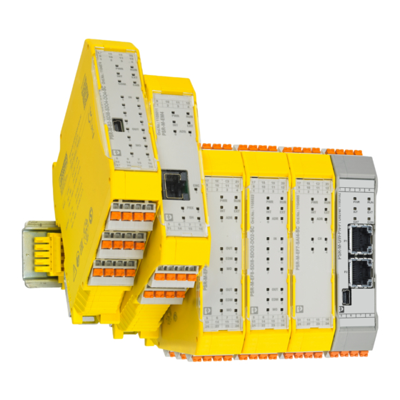
Phoenix Contact PSRmodular User Manual (236 pages)
Configurable safety system
Brand:
Phoenix Contact
| Category:
Safety Equipment
| Size: 19 MB
Table of Contents
Table of Contents
3
For Your Safety
7
Identification of Warning Notes
7
Qualification of Users
7
Field of Application of the Product
8
Intended Use
8
Product Changes
12
Safety Notes
12
General Safety Notes
12
Electrical Safety
13
Safety of Machines or Systems
14
Safety When Starting Applications
15
Directives and Standards
15
Documentation
16
System Description
17
Psrmodular Safety System: Structure and Method of Operation
17
Mounting Location
20
Safety Notes
20
Installation
20
Connection Technology
21
Mechanical Attachment
21
Electrical Requirements
22
Using the System
23
Safe State
24
System Restart Behavior
25
Diagnostic Tools
26
Error State
26
Error Detection
26
Password Protection
27
Signal Description
29
Motion Signals
33
Analog Signals
35
Psrmodular Software: Basics
37
Installing the Psrmodular Software
37
Basic Knowledge
38
The Tool Bar
39
Creating a New Project
40
Changing the Hardware Configuration
41
Changing Project Information
42
Function Windows: Items - Operator - Configuration
43
Creating the Safety Logic
44
Calling Functions in the Context Menu
45
Project Example
46
Saving the Project
46
Validating the Project
46
Resource Allocation
47
Project Report
48
Connecting to the Base Module
50
Password Protection
51
Establishing a USB Connection
52
Figure 4-13 Changing Passwords
52
Figure 4-14 Level 2 Password Entry for USB Connection
52
Figure 4-15 Log File Display
53
Figure 4-17 Example Error Display for Configuration Errors
54
Figure 4-16 Display of the System Configuration
54
Monitor (Status of I/Os)
55
Figure 4-18 Example Monitor Display for the I/Os
55
Monitor Graphic
56
Figure 4-19 Graphic Monitor Display
56
System Test
57
Figure 4-20 System Test Example
57
Figure 4-21 out Status Transition at the GUARD-MONITORING Function Block
57
Figure 5-1 "DUAL-OUTPUT" Function Block (Safe Outputs)
59
Item Function Blocks
59
Output Item
59
Items and Operators of the Psrmodular Software
59
Figure 5-2: Basic Circuit Diagram of the Outputs for the DUAL-OUTPUT
60
Figure 5-3 Manual (Left) and Monitored (Right) Reset
60
Figure 5-4: Correct (Left) / Incorrect (Middle and Right) Feedback Signal
61
Figure 5-5: "SINGLE/DUAL-OUTPUT" Function Block (Safe Output)
62
Figure 5-6: Project Example with "SINGLE/DUAL-OUTPUT" Function Block
63
Figure 5-7: Basic Circuit Diagram of the Outputs for the SINGLE/DUAL- OUTPUT Function Block
63
Figure 5-9: Correct (Left) / Incorrect (Middle and Right) Feedback Signal
64
Figure 5-8: Manual (Left) and Monitored (Right) Reset
64
Figure 5-10 "MONITORING-OUT" Function Block
65
Figure 5-11 External Output Signal (EQ)
65
Figure 5-12 Outputs with Category 1 Single Relays
66
Figure 5-13: Example with External (Left) and Internal (Right) Relay
67
Figure 5-14: Outputs with Category 2 Single Relays with "OTE" Outputs
67
Figure 5-15: Example for Two Safety Functions each in Accordance with Cat
68
Figure 5-16 Example with Internal Relay and Monitored Solenoid Valves (Left) and with External Contactors with Feedback (Right)
68
Figure 5-17: Manual (Left) and Monitored (Right) Reset
69
Figure 5-18 Correct (Left) / Incorrect (Middle and Right) Feedback Signal
70
INPUT Item
71
Figure 5-19: "E-STOP" Function Block (Emergency Stop)
71
Figure 5-20: Manual (Left) and Monitored (Right) Reset
72
Figure 5-21: "GUARD-MONITORING (2CH)" Function Block
73
Figure 5-22: Manual (Left) and Monitored (Right) Reset
74
Figure 5-23 GUARD-MONITORING (1CH) Function Block
75
Figure 5-24 Time Diagram for "Manual" Reset (Left) and "Monitored" Reset (Right)
75
Figure 5-25: LOCK FEEDBACK Function Block
77
Figure 5-26 "ENABLE" Function Block
78
Figure 5-27 Time Diagram for "Manual" Reset (Left) and "Monitored" Reset (Right)
78
Figure 5-28 Connection Examples with One Contact (Left) and Two Contacts (Right)
79
Figure 5-29: "ESPE" Function Block (Light Grid/Safety Laser Scanner)
80
Figure 5-30: Time Diagram for "Manual" Reset (Left) and "Monitored" Reset (Middle), and Connection Example (Right)
81
Figure 5-31: "FOOTSWITCH" Function Block (Safety Foot Switch)
82
Figure 5-32 Time Diagram for "Manual" Reset (Left) and "Monitored" Reset (Right)
83
Figure 5-33 Connection Examples with One Contact (Left) and Two Contacts (Right)
83
Figure 5-34: "MODE-SELECTOR" Function Block (Mode Selector Switch)
84
Figure 5-35: "TESTABLE-SENSOR" Function Block (Electro-Sensitive Protec- Tive Equipment)
85
Figure 5-36: Time Diagram for "Manual" Reset (Left) and "Monitored" Reset (Middle), and a Connection Example
85
Figure 5-37: "TWO-HAND" Function Block (Two-Hand Operation)
86
Figure 5-38: "NETWORK_IN" Function Block (Line Emergency Stop)
87
Figure 5-39 "SENSOR" Function Block
88
Figure 5-40: Time Diagram for "Manual" Reset (Left) and "Monitored" Reset (Right)
89
Figure 5-41: "S-MAT" Function Block (Safety Mat)
90
Figure 5-42: Time Diagram for "Manual" Reset (Left) and "Monitored" Reset (Middle), and a Connection Example
91
Figure 5-44: Time Diagram for "Manual" Reset (Left) and "Monitored" Reset (Right)
92
Figure 5-43: "SWITCH" Function Block (Switch/Pushbutton)
92
Figure 5-45: "ENABLE SWITCH" Function Block
94
Figure 5-46: "TESTABLE SAFETY DEVICE" Function Block (Safety Switch)
96
Figure 5-47: Time Diagram for "Manual" Reset (Left) and "Monitored" Reset (Right)
97
Figure 5-48: External Input Signal (EI)
98
Figure 5-49 FALSE/TRUE
99
Figure 5-50 Comments Item
99
Figure 5-51 Title Item
99
Figure 5-52: Example of an "OVER-SPEED" Function Block with Activated "Error" Output
100
General Information on the "Error Out" Parameter
100
Speed Control
100
Function Blocks
101
Figure 5-53: "OVER-SPEED" Function Block with SLS
101
Figure 5-54: Example of an Axis with Clockwise Rotation
102
Figure 5-55: Example with Four Thresholds
103
Figure 5-56 Selection Options for Proximity Switches
104
Figure 5-57: Overlapping Proximity Switches
105
Figure 5-58: Slider for Setting the Hysteresis Parameter
105
Figure 5-59 "SPEED-RANGE" Function Block (SSR, Safe Speed Range)
107
Figure 5-60: Selection Options for Proximity Switches
108
Figure 5-61: Overlapping Proximity Switches
109
Figure 5-62: Slider for Setting the Hysteresis Parameter
109
Figure 5-63: "ZERO-SPEED" Function Block (Zero-Speed Monitoring)
111
Figure 5-64: Selection Options for Proximity Switches
112
Figure 5-65: Overlapping Proximity Switches
113
Figure 5-66: Slider for Setting the Hysteresis Parameter
113
Figure 5-67 "ZERO-AND-OVER-SPEED" Function Block
115
Figure 5-68: Example of an Axis with Clockwise Rotation
116
Figure 5-69: Example with Four Thresholds
117
Figure 5-70 Selection Options for Proximity Switches
118
Figure 5-71: Overlapping Proximity Switches
119
Figure 5-72: Slider for Setting the Hysteresis Parameter
119
Analog Function Block
121
ANALOG INPUT Function Block
121
Figure 5-73 ANALOG INPUT Function Blocks for Standard Current Signals (Left) and Standard Voltage Signals (Right)
121
Figure 5-74 "Single" Input Type (Above) and "Redundant" Input Type (Below)
121
Figure 5-75 "ANALOG INPUT" Parameter Overview
121
Figure 5-76 Additional Parameters for "Redundant" Input Type
122
Figure 5-77 Measured Value Error for Two-Channel Sensors
123
Figure 5-78: Diagram of a Pair of Sensors with Identical (Left) and Differ
124
Figure 5-79: Parameters for the "Window Comparator" Option
125
Figure 5-80 Measured Value Representation with "Window Comparator
126
Figure 5-81 Parameters for the "Enable Threshold 1" / "Enable Threshold 2" Options
126
Figure 5-82: Function Example of the Comparator with Threshold
127
Figure 5-83 Selection Options for "Samples Per Second
128
Figure 5-84 "Current Limits" Parameter
130
Figure 5-85: Example Circuit Diagram for "Current Limits
130
Figure 5-86: "Current Limits/Voltage" Parameter
130
Figure 5-87: Function Block for "Analog Output" Option
131
Figure 5-88: Example Circuit Diagram for "Analog Output
132
Figure 5-89: Function Block for "Enable Error Out" Option
132
Operator Function Blocks
133
Logical Operators
133
Figure 5-90 "AND" Operator
133
Figure 5-91 "NAND" Operator
134
Figure 5-92 "NOT" Operator
134
Figure 5-93 "OR" Operator
135
Figure 5-94 "NOR" Operator
136
Figure 5-95 "XOR" Operator
136
Figure 5-96 "XNOR" Operator
137
Figure 5-97: "LOGICAL MACRO" Operator
138
Figure 5-98: Example for "LOGICAL MACRO" with Just One Input for "In- Put Logic 2
138
Figure 5-99 "MULTIPLEXER" Operator
139
Figure 5-100: "DIGITAL COMPARATOR" Operator (Comparison with Constant)
140
Figure 5-101: "DIGITAL COMPARATOR" (Signals Comparator)
141
Figure 5-102: "D FLIP-FLOP" Operator
143
MEMORY Operators
143
Figure 5-103 "T FLIP-FLOP" Operator
144
Figure 5-104 "SR FLIP-FLOP" Operator
144
Figure 5-105: "MANUAL RESET" Operator
145
Figure 5-106: "MONITORED RESET" Operator
146
Figure 5-107: "MACRO MANUAL RESET" Operator
147
Figure 5-108: "MACRO MONITORED RESET" Operator
148
Figure 5-109: "PRE-RESET" Operator
149
Figure 5-111: Example of Position Detection for the Guard Locking Pin in Ac- Cordance with the Closed-Circuit Principle as Well as Safety Door Monitoring
151
GUARD-LOCKING Operator
151
Figure 5-110: "GUARD-LOCKING" Operator
151
Figure 5-112: GUARD-LOCKING Example in Operating Mode Without Position Monitoring of the Safety Door
153
Figure 5-113 GUARD-LOCKING Example in Operating Mode Without Position Monitoring of the Safety Door
154
Figure 5-114 Signal Behavior in the Example for the "GUARD-LOCKING" Function Block in Operating Mode Without Position Monitoring of the Safety Door
154
Figure 5-115: "GUARD-LOCKING" Example in Operating Mode with Position Monitoring of the Safety Door
155
Figure 5-116: "GUARD-LOCKING" Example in Operating Mode with Position Monitoring of the Safety Door
156
Figure 5-118 "GUARD-LOCKING" Example in "Mandatory Safety Door Opening" Operat- Ing Mode
158
Figure 5-120: Signal Behavior in the Example for the "GUARD-LOCKING" Function Block in "Mandatory Safety Door Opening" Operating Mode
159
Figure 5-119: "GUARD-LOCKING" Example in "Mandatory Safety Door Open
159
Figure 5-117: Signal Behavior in the Example for the "GUARD-LOCKING
159
Figure 5-121: Signal Behavior in the Example for the "GUARD-LOCKING" Function Block in "Mandatory Safety Door Opening" Operating Mode with Error (Door Is Not Opened Despite Request)
161
Figure 5-122: "Manual" (Left) and "Monitored" (Right) Reset
161
COUNTER Operators
163
Figure 5-123: "COUNTER" Operator
163
Figure 5-124 Example Pulse Diagram for "COUNTER" with "Automatic" Counter Type
164
Figure 5-125 Example Pulse Diagram for "COUNTER" with "Manual" Counter Type
164
Figure 5-126 Example Pulse Diagram for "COUNTER" with "Manual/Automatic" Counter Type
164
Figure 5-127: "COUNTER COMPARATOR" Operator
165
TIMER Operators
166
Figure 5-129: Time Diagram for "MONOSTABLE" Operator When "Rising Edge" Parameter Is Selected
166
Figure 5-128 "MONOSTABLE" Operator
166
Figure 5-130: Time Diagram for "MONOSTABLE" Operator When "Rising Edge" Parameter Is Not Selected
167
Figure 5-131: "MONOSTABLE_B" Operator
167
Figure 5-132: Time Diagram for "MONOSTABLE_B" Operator When "Rising Edge" Parameter Is Selected
168
Figure 5-133: Time Diagram for "MONOSTABLE_B" Operator When "Rising Edge" Parameter Is Not Selected
168
Figure 5-134: "PASSING MAKE CONTACT" Operator
168
Figure 5-137: "DELAY" Operator
169
Figure 5-135: Time Diagram for "PASSING MAKE CONTACT" Operator
169
Figure 5-136: Time Diagram for "PASSING MAKE CONTACT" Operator with Activated "Retriggerable" Option
169
Figure 5-138: Time Diagram for "DELAY" Operator When "Rising Edge" Pa- Rameter Is Selected
170
Figure 5-139: Time Diagram for "DELAY" Operator When "Rising Edge" Pa- Rameter Is Not Selected
170
Figure 5-140 "LONG DELAY" Operator
171
Figure 5-141: Time Diagram for "LONG DELAY" Operator When "Rising Edge" Parameter Is Selected
171
Figure 5-142 Time Diagram for "LONG DELAY" Operator When "Rising Edge" Parameter Is Not Selected
172
Figure 5-143 "DELAY COMPARATOR" Operator
172
Figure 5-144 "DELAY LINE" Operator
173
Figure 5-145: Time Diagram for "DELAY LINE" Operator
173
Figure 5-146: "LONG DELAY LINE" Operator
174
Figure 5-147: Time Diagram for "LONG DELAY LINE" Operator
174
Figure 5-148: "CLOCKING" Operator
175
Figure 5-149: Duty Cycle Examples for HIGH to LOW
176
MUTING Operators
177
Figure 5-150 Sensor Arrangement for "MUTING "Con
177
Figure 5-151 "MUTING "Con"" Operator
178
Figure 5-153 "MUTING "L"" Operator
180
Figure 5-152 Sensor Arrangement for "MUTING "L
180
Figure 5-155 "MUTING "Seq"" Operator
182
Figure 5-154 Sensor Arrangement for "MUTING "Seq
182
Figure 5-156 Sensor Arrangement for "MUTING "T
185
Figure 5-157 MUTING "T" Operator
185
Figure 5-158: "MUTING OVERRIDE" Operator
186
Figure 5-159: Manual (Left) and Monitored (Right) Reset
187
Figure 5-160 "MUTING OVERRIDE" Application Example
188
Figure 5-161 "ANALOG COMPARATOR" Operator
189
Figure 5-162 "ADDER" Operator for Sum Calculation (Left) and Difference Calculation (Right)
189
Analog Comparator
189
Adder
189
Analog Operators
189
Equality Check
190
Figure 5-163 "Equality Check" Operator
190
Miscellaneous
192
Other Operators
192
Figure 5-164: "SERIAL OUTPUT" Operator
192
Figure 5-165: "Asynchronous Synchronization" Mode Selection
192
Figure 5-166: "Synchronous Synchronization" Mode Selection
193
Figure 5-167: "NETWORK" Operator
193
Figure 5-168 Circuit Diagram Application Example of the "NETWORK" Function Block for Category 2 (ISO 13849-1)
195
Figure 5-169: Data Flow Network Diagram for the "NETWORK" Application Ex
196
Figure 5-170: Logic Block Diagram of the Network Safety Function
196
Figure 5-172: Data Flow Network Diagram for the "NETWORK" Application Ex
196
Figure 5-171: Circuit Diagram Application Example of the "NETWORK" Func
197
Figure 5-173: Logic Block Diagram of the Network Safety Function
198
Figure 5-174: Emergency Stop Example for a Network with Four Base Mod- Ules
199
Figure 5-175 "RESET" Operator
200
Figure 5-176 Time Diagram for Reset Generated by the "RESET" Operator
200
Figure 5-177 "EDM" Function Block
200
Figure 5-178: Example of a Safe Output with Correct Feedback Signal (Left) / Incorrect Feedback Signal (Middle and Right)
201
Figure 5-179: Application Example for the EDM Function Block
201
Figure 5-180 "Connector" Variable
202
Figure 5-181 "TERMINATOR" Operator
202
Simulator Features
203
Figure 5-182: Simulator Icons
203
Figure 5-183 Simulation Icons in the Tool Bar
204
Figure 5-184 Button in Function Blocks for Activating the Output
205
Figure 5-185 Pop-Up Window for Entering a Frequency Value
205
Figure 5-186 Display of Results in a Simulation Graphic
206
Figure 5-187 "Managing Dynamic Simulation" Selection Menu
206
Figure 5-188 Template Text File before (Left) and after (Right) Editing
207
Figure 5-189 Signal Selection
208
Figure 5-191 Specification Text File of the Application Example for a Dynamic Simulation
209
Figure 5-190 Safety Program of the Application Example for a Dynamic Simulation
209
Figure 5-192 Simulation Graphic for the Application Example
210
Installation and Startup
211
Example for Installation and Startup
211
Diagnostics
213
Device Diagnostics
213
System Diagnostics
213
Psrmodular Error Codes
213
Error History
215
Decommissioning and Disposal
217
Maintenance, Repair, Decommissioning, and Disposal
217
Repair
217
Maintenance
217
A Technical Appendix
219
A 1 Response Times of the Psrmodular System
219
B Appendix For Document Lists
221
List of Figures
221
Section 5
222
C Revision History
231
Advertisement
Advertisement
Related Products
Phoenix Contact PSR-24DC/ESD/5X1/1X2/300 Series
Phoenix Contact PSR-SPP- 24DC/ESD/5X1/1X2/300
Phoenix Contact PSR-M-B1
Phoenix Contact PSR-M-B2
Phoenix Contact PSRmultifunction Series
Phoenix Contact PSR-MXF1/4x1/2x2/B
Phoenix Contact PSR-MXF2/4x1/2x2/B
Phoenix Contact PSR-MXF3/4x1/2x2/B
Phoenix Contact PSR-MXF4/4x1/2x2/B
Phoenix Contact PSR-MM35
Phoenix Contact Categories
Controller
Control Unit
Switch
Power Supply
Media Converter
More Phoenix Contact Manuals
Login
Sign In
OR
Sign in with Facebook
Sign in with Google
Upload manual
Upload from disk
Upload from URL