Sign In
Upload
Manuals
Brands
Pfeiffer Vacuum Manuals
Industrial Equipment
TC 1200 PN
Pfeiffer Vacuum TC 1200 PN Turbo Pump Manuals
Manuals and User Guides for Pfeiffer Vacuum TC 1200 PN Turbo Pump. We have
1
Pfeiffer Vacuum TC 1200 PN Turbo Pump manual available for free PDF download: Operating Instructions Manual
Pfeiffer Vacuum TC 1200 PN Operating Instructions Manual (52 pages)
Electronic drive unit
Brand:
Pfeiffer Vacuum
| Category:
Industrial Equipment
| Size: 3 MB
Table of Contents
Telegram Example
2
Table of Contents
3
About this Manual
7
Validity
7
Applicable Documents
7
Target Group
7
Conventions
7
Instructions in the Text
7
Pictographs
7
Stickers on the Product
8
Abbreviations
8
Tbl. 1: Stickers on the Product
8
Trademark Proof
9
Tbl. 2: Abbreviations Used in this Document
9
Safety
10
General Safety Information
10
Safety Instructions
10
Safety Precautions
11
Limits of Use of the Product
12
Tbl. 3: Permissible Ambient Conditions
12
Proper Use
13
Foreseeable Misuse
13
Product Description
14
Identifying the Product
14
Product Features
14
Function
14
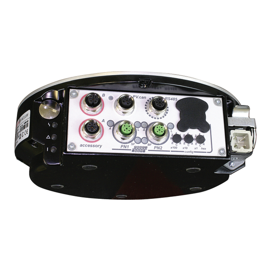
Fig. 1: Connection Panel TC 1200 PN
14
Scope of Delivery
15
Connections
15
Tbl. 6: Connection Description of the Electronic Drive Unit
15
Installation
16
Connection Diagram
16
Profinet" Connection
17
Mains Power Supply
17
Tbl. 7: Terminal Assignment of the "Profinet" M12 Connection
17
Fig. 2: Diagram and Assignments of the Connection Panel
17
Tbl. 8: Terminal Lay-Out of the Power Supply Connector
18
Interfaces
19
Profinet Interface
19
Making Connections
19
Defining Device ID
19
Cyclic Process Data
19
Modules of the Cyclic Process Data
19
Tbl. 9: Modules of the Cyclic Process Data
19
Tbl. 10: Speed Controlled TMP Assembly: Output Data (PLC to TC)
20
Tbl. 11: Speed Controlled TMP Assembly: Input Data (TC to PLC)
20
Tbl. 12: Electronictemp: Input Data (TC to PLC)
20
Tbl. 13: Motortemp: Input Data (TC to PLC)
20
Tbl. 14: Dclinkvoltage: Input Data (TC to PLC)
20
Tbl. 15: Dclinkcurrent: Input Data (TC to PLC)
20
Tbl. 16: Bearingtemp: Input Data (TC to PLC)
21
Tbl. 17: Drivetemp: Input Data (TC to PLC)
21
Tbl. 18: Bottomtemp: Input Data (TC to PLC)
21
Tbl. 19: Drivepower: Input Data (TC to PLC)
21
Tbl. 20: Errorcode: Input Data (TC to PLC)
21
Tbl. 21: Rotortemp: Input Data (TC to PLC)
21
Parameterization
22
Acyclic Data
23
Data Types
23
Tbl. 25: Parameterization Data Format
23
Tbl. 26: "Write Record" Service
23
Tbl. 27: "Read Record" Service
23
Tbl. 28: Profinet Data Types
23
Interface RS-485
24
Connection Options
24
Fig. 3: Connection Options Via Interface RS-485
24
Cross-Linking Via the RS-485 Connection
25
Pfeiffer Vacuum Protocol for RS-485 Interface
25
Telegram Frame
25
Fig. 4: Cross-Linking of Turbopumps with Integrated Electronic Drive Unit Via Interface
25
Telegram Description
26
Telegram Example
26
Data Types
27
Parameter Set
28
General
28
Control Commands
28
Tbl. 31: Explanation and Meaning of the Parameters
28
Status Requests
31
Set Value Settings
32
Tbl. 33: Status Requests
32
Additional Parameters for the Control Unit
33
Operation
34
Configuring the Connections with the Pfeiffer Vacuum Parameter Set
34
Configuring the Accessory Connections
34
Select Interfaces
34
Tbl. 36: Accessory Connections
34
Tbl. 37: Parameter [P:060]
34
Operating Modes
35
Gas Type-Dependent Operation
35
Tbl. 38: Parameter [P:061]
35
Fig. 5: Schematic Diagram of Power Characteristics, Example of Heavy Gases
35
Set Value Power Consumption
36
Run-Up Time
36
Rotation Speed Switch Points
36
Fig. 6: Rotation Speed Switch Point 1 Active
36
Rotation Speed Setting Mode
37
Fig. 7: Rotation Speed Switch Points 1 & 2 Active, [P:701] > [P:719]
37
Fig. 8: Rotation Speed Switch Points 1 & 2 Active, [P:701] < [P:719]
37
Standby
38
Confirming Speed Specification
38
Backing Pump Operating Modes
38
Tbl. 39: Characteristic Nominal Rotation Speeds of the Turbopumps
38
Tbl. 40: Backing Pump Operating Modes
39
Backing Pump Standby Mode
40
10Operation with Accessories
40
11Venting Modes
40
Switching on the Turbopump
41
Switching off the Turbopump
41
Operation Monitoring
41
Operating Mode Display Via LED
41
Tbl. 41: Behavior and Meaning of the Leds on the Electronic Drive Unit
41
Operating Mode Display for Profinet LED
42
Temperature Monitoring
42
Tbl. 42: Behavior and Meaning of the Profinet LED
42
Recycling and Disposal
43
General Disposal Information
43
Dispose of Electronic Drive Unit
43
Malfunctions
44
General
44
Error Codes
44
Warning and Malfunction Messages When Operating with Control Units
47
Service Solutions by Pfeiffer Vacuum
48
EC Declaration of Conformity
50
Declaration of Conformity
51
Advertisement
Advertisement
Related Products
Pfeiffer Vacuum TPR 271
Pfeiffer Vacuum TTR 101
Pfeiffer Vacuum TTR 101 S2
Pfeiffer Vacuum TC 120
Pfeiffer Vacuum TC1200
Pfeiffer Vacuum TC 1200 E74
Pfeiffer Vacuum TC 1200 PB
Pfeiffer Vacuum TC 1200 EC
Pfeiffer Vacuum TC 1200 DN
Pfeiffer Vacuum TC 110
Pfeiffer Vacuum Categories
Water Pump
Control Unit
Measuring Instruments
Industrial Equipment
Security Sensors
More Pfeiffer Vacuum Manuals
Login
Sign In
OR
Sign in with Facebook
Sign in with Google
Upload manual
Upload from disk
Upload from URL