Sign In
Upload
Manuals
Brands
Pfeiffer Vacuum Manuals
Measuring Instruments
PT Q80 217 220
Pfeiffer Vacuum PT Q80 217 220 Measuring Manuals
Manuals and User Guides for Pfeiffer Vacuum PT Q80 217 220 Measuring. We have
1
Pfeiffer Vacuum PT Q80 217 220 Measuring manual available for free PDF download: Operating Instructions Manual
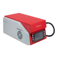
Pfeiffer Vacuum PT Q80 217 220 Operating Instructions Manual (120 pages)
Gas analysis system
Brand:
Pfeiffer Vacuum
| Category:
Measuring Instruments
| Size: 16 MB
Table of Contents
Table of Contents
3
About this Manual
10
Validity
10
Applicable Documents
10
Tbl. 1: Applicable Documents
10
Variants
11
Target Group
11
Conventions
12
Instructions in the Text
12
Pictographs
12
Stickers on the Product
12
Orientation Left/Right
13
Abbreviations
13
Fig. 1: Position of the Stickers on the Product
13
Trademark Proof
14
Safety
15
General Safety Information
15
Safety Instructions
15
Safety Precautions
18
Limits of Use of the Product
19
Proper Use
19
Foreseeable Misuse
19
Tbl. 5: Permissible Ambient Conditions
19
Personnel Qualification
20
Ensuring Personnel Qualification
20
Personnel Qualification for Maintenance and Repair
20
Advanced Training with Pfeiffer Vacuum
20
Product Description
21
Functional Description
21
Omnistar
21
Fig. 2: Vacuum Diagram of the Omnistar
21
Thermostar
22
Corrosive Gas Version
22
Controls and Indicators
22
Version with Display
22
Fig. 3: Vacuum Diagram of Thermostar
22
Fig. 4: Additionally Sealing Gas Supply in Corrosive Gas Version
22
Version Without Display
23
Tbl. 6: Symbols and Colors of the Status and Components Icons
23
Fig. 5: Display with Operator Keys
23
Layout of the Unit
24
Basic Unit
24
Terminal Area
24
Fig. 6: Housing Parts
24
Gas Inlet System
25
Fig. 7: Connection Panel with Interfaces and Connections
25
Calibration Unit
26
Fig. 8: Gas Inlet Systems
26
High Vacuum Side System
27
Fore-Vacuum System
27
Fig. 9: Calibration Unit at the Gas Inlet
27
Fig. 10: Diaphragm Pump
27
Sealing Gas System
28
Gas Analysis Unit
28
Fig. 11: Sealing Gas System
28
Heating and Insulation
29
Tbl. 8: Heating Units on the Unit
29
Fig. 12: Gas Analysis Unit Components
29
Fig. 13: Vacuum Chamber Heating and Insulation
30
Fig. 14: Gas Inlet Heating
30
10Electronic Components
31
Fig. 15: Capillary Heating
31
Identifying the Product
32
Scope of Delivery
32
Fig. 16: Electronic Components
32
Fig. 17: Assembly Aid for Analyzer QMA
33
Fig. 18: Special Tool for the Orifice of the Gas Inlet System
33
Fig. 19: Mounting Aid for Calibration Gas Support
33
Transport and Storage
34
Transporting Product
34
Fig. 20: Transport Protection for the Diaphragm Pump
34
Storing Product
35
Installation
36
Ensuring Ventilation
36
Removing Transport Protection for the Diaphragm Pump
36
Fig. 21: Minimum Lateral Distances of the Unit
36
Fig. 22: Transport Protection for the Diaphragm Pump
36
Establishing the Ethernet Connection
37
Connecting the Exhaust Duct
37
Trimming the Exhaust Gas Hose
37
Connecting Exhaust Gas Hose
37
Fig. 23: Trimming the Exhaust Gas Hose
37
Connecting the Sealing Gas Line
38
Trimming the Sealing Gas Hose
38
Fig. 24: Connecting Exhaust Gas Hose
38
Fig. 25: Trimming the Sealing Gas Hose
38
Connecting the Capillary
39
Fig. 26: Connecting the Sealing Gas Line
39
Connecting the Omnistar Stainless Steel Capillary
40
Connecting the Thermostar Quartz Capillary
40
Adapting Position of the Capillary Hose
40
Fig. 27: Connecting the Capillary
40
Establishing a Network Connection
41
IP Addresses
41
Fig. 28: Position of the Capillary Hose Upon Delivery
41
Sub-Networks
42
Tbl. 9: Examples for Sub-Networks
42
Changing IP Address for the GSD
43
Changing the Host Computer IP Address
43
Fig. 29: Changing IP Address of the GSD 350 Via the Web Interface
43
Connecting the Functional Earth
44
Fig. 30: Connection for Functional Earth
44
Establishing Mains Connection
45
Installing the PV Massspec Software
45
Fig. 31: Mains Connection with IEC 320 C13 Socket
45
Interfaces and Connections
46
Mains Connection
46
Ground Terminal
46
User I/O" Connection
46
Fig. 32: Mains Connection with Main Switch and Fuse
46
AUX IO" Connection
47
Fig. 33: "USER I/O" Connection
47
Ethernet" (LAN) Connection
48
Fig. 34: "AUX IO" Connection
48
Tbl. 10: Status of the Ethernet Connection
49
Fig. 35: "Ethernet" (LAN) Connection
49
Commissioning
50
Switching on Unit
50
Starting Pumping System
50
Fig. 36: "Dashboard" Screen after Starting the Program
50
Fig. 37: "Control" Screen
51
Operation Via the Display
52
Dashboard" Screen
52
Menu Structure with Functions
53
Fig. 38: "Dashboard" Screen
53
Info" Menu
54
Tbl. 11: Menu Structure with Functions
54
Settings" Menu
55
Creating and Editing Measurement Recipes
56
Fig. 39: Example of Parameter Setting
56
Fig. 40: "Recipes" Submenu
56
Fig. 41: Measurement Recipe for "Spectrum Scan" Measuring Mode
57
Fig. 42: Measurement Recipe for " Selected Masses" Measuring Mode
57
Adjusting the Heating Units
58
Fig. 43: Measurement Recipe for "Selected Masses - Special" Measuring Mode
58
Adjusting Sensors
59
Fig. 44: Tempering Mode of the Vacuum Chamber
59
Changing User Settings
60
Setting Autostart Functions
60
Fig. 45: "User Settings" Submenu
60
Fig. 46: "Autostart" Submenu
60
Setting Network Parameters
61
Resetting the Unit to the Factory Settings
61
Fig. 47: "Network" Submenu
61
Service" Submenu
62
Messages" Menu
62
Fig. 48: "Factory Settings" Submenu
62
Fig. 49: Example of a Malfunction Message
62
Control" Menu
63
Fig. 50: Example of Older Messages
63
Pumping down the Vacuum System
64
Venting Vacuum System
64
Fig. 51: "Control" Menu
64
Switching Heating Units on and off
65
Opening and Closing Gas Inlet (Omnistar)
65
Baking out the Vacuum Chamber
66
Switching Emission on and off
66
Switching Electron Multiplier on and off
66
Opening and Closing Calibration Valve
67
Measurement" Menu
67
Fig. 52: Recipe Selection
68
Decommissioning
69
Maintenance
70
Maintenance Work and Intervals
70
Maintaining the Basic Unit
72
1Removing/Attaching Gas Inlet Cover
72
Fig. 53: Removing/Attaching Gas Inlet Cover
72
2Removing/Attaching Side Covers
73
Fig. 54: Removing/Attaching Side Covers
73
3Removing/Attaching Housing Cover
74
Fig. 55: Removing/Attaching Housing Cover
74
4Cleaning Housing Parts
75
5Cleaning the Protection Screens on the Fans
76
Maintaining the High Vacuum System
76
1Replacing Operating Fluid Reservoir on Turbopump
76
2Replacing the Venting Valve
77
Maintaining the Fore-Vacuum System
77
1Replacing Diaphragm Pump
77
Fig. 56: Unit Underside
77
Fig. 57: Replacing Diaphragm Pump
78
Fig. 58: Connect the Exhaust Gas and Intake Hose, and Draw off
78
2Replacing Diaphragm Pump Diaphragm
79
Maintaining the Gas Analysis Unit
80
1Maintaining QMA 250 M Analyzer
80
Fig. 59: Prismapro Quadrupole Mass Spectrometer
80
Tbl. 13: Determined Sensitivity of the Mass Spectrometer
81
Fig. 60: Groove on Analyzer
81
2Maintaining Total Pressure Gauge
82
Fig. 61: Total Pressure Gauge on the Gas Analysis Unit
82
Maintaining Gas Inlet System of Omnistar
83
1Removing Gas Inlet Flange
83
Fig. 62: Part of Internal Gas Guide on Omnistar
83
Fig. 63: Disassemble the Valve Block
84
2Replacing Orifice
85
3Replacing Interior Gas Guide and Orifice
85
Fig. 64: Gas Guide Approx. 1-2 MM Behind the End of the Ceramic Sleeve
85
4Installing Gas Inlet Flange
86
Maintaining Gas Inlet System of Thermostar
87
1Removing Gas Inlet Flange
87
Fig. 65: Parts of the Internal Gas Guide on the Thermostar
87
2Replacing Orifice
88
Fig. 66: Removing Gas Inlet Flange
88
3Replacing Interior Gas Guide and Orifice
89
Fig. 67: Gas Guide Approx. 1-2 MM Behind the End of the Ceramic Sleeve
89
4Installing Gas Inlet Flange
90
Servicing Capillary
90
1Shortening Stainless Steel Capillaries
91
Fig. 68: Length of Stainless Steel Capillary with Clamping Collar Fitting
91
Fig. 69: Notch and Snap off the Stainless Steel Capillary
91
2Replacing Stainless Steel Capillary
92
Fig. 70: Clamp Collar Fitting for Stainless Steel Capillary
92
3Trimming Quartz Capillaries
93
Fig. 71: Notching and Snapping off the Quartz Capillary
93
4Replacing Quartz Capillary
94
Fig. 72: Front Fitting of Quartz Capillary
94
Maintaining the Heating Units
95
1Replacing the Capillary Hose
95
2Maintaining the Gas Inlet Heating
95
3Servicing the Vacuum Chamber Heating
95
Maintaining Electronic Components
95
Replacing Display
95
Replacing the Poe Injector
96
Replacing the Mainboard
96
Replacing the Power Supply Pack
96
Replacing the QME 250 Electronic Unit
96
Fig. 73: Replacing Display
96
Replacing the TC 110 Electronic Drive Unit on the Turbopump
97
Maintaining the Calibration Unit
97
Refilling Calibration Medium
97
Fig. 74: Calibration Unit
97
Replacing the Calibration Valve
98
Additional Maintenance Work for the Corrosive Gas Version
98
Replacing Sealing Gas Valve
98
Replacing Manual Pressure Regulator
98
Replacing Digital Pressure Switch
98
Troubleshooting
99
Tbl. 14: Troubleshooting
102
Shipping
103
Recycling and Disposal
104
General Disposal Information
104
Dispose of a Gas Analysis System
104
Service Solutions by Pfeiffer Vacuum
105
Spare Parts
107
Tbl. 15: Spare Parts and Components, Maintenance Level
108
Tbl. 16: Hose Colors and Dimensions
108
Tbl. 17: Components for Hose Connections
109
Special Tool
110
Tbl. 18: Special Tool
110
Fig. 75: Wrench for Turbopump Housing Cover
110
Fig. 76: Centering Gauge for QMA
110
Fig. 77: Mounting Aid for Calibration Gas Support
110
Accessories
111
Accessory Information
111
Ordering Accessories
111
Fig. 78: Capillary Hose Adapter
111
Technical Data and Dimensions
112
General
112
Technical Data
112
Dimensions
114
Fig. 79: Dimensions
114
Certification
115
Declaration of Conformity
116
Advertisement
Advertisement
Related Products
Pfeiffer Vacuum PT Q80 217 120
Pfeiffer Vacuum PTQ80 217 110
Pfeiffer Vacuum PT Q80 517 230
Pfeiffer Vacuum PT Q80 617 310
Pfeiffer Vacuum PT Q80 617 230
Pfeiffer Vacuum PT Q80 617 110
Pfeiffer Vacuum PT Q80 617 320
Pfeiffer Vacuum PT Q80 617 330
Pfeiffer Vacuum PT Q80 617 220
Pfeiffer Vacuum PT Q80 117 330
Pfeiffer Vacuum Categories
Water Pump
Control Unit
Measuring Instruments
Industrial Equipment
Security Sensors
More Pfeiffer Vacuum Manuals
Login
Sign In
OR
Sign in with Facebook
Sign in with Google
Upload manual
Upload from disk
Upload from URL