User Manuals: Peri VST Heavy-Duty Shoring Tower
Manuals and User Guides for Peri VST Heavy-Duty Shoring Tower. We have 1 Peri VST Heavy-Duty Shoring Tower manual available for free PDF download: Instructions For Assembly And Use
Peri VST Instructions For Assembly And Use (96 pages)
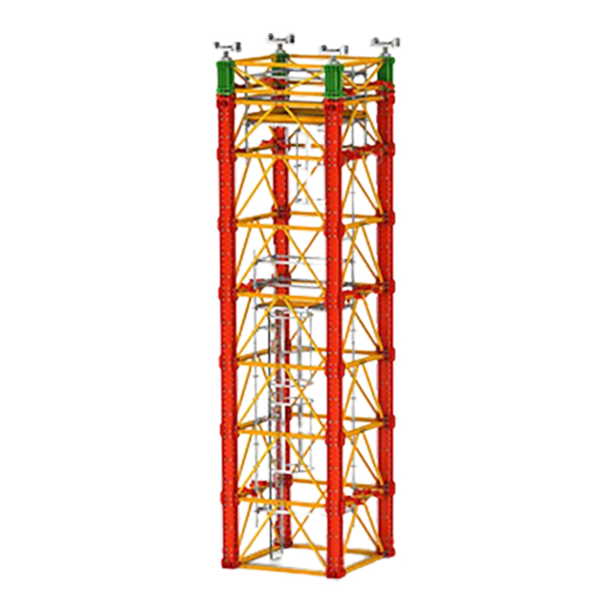
Heavy-Duty Shoring Tower
Brand: Peri
|
Category: Construction Equipment
|
Size: 17 MB
Table of Contents
Advertisement
Advertisement