Sign In
Upload
Manuals
Brands
PEP Modular Computers Manuals
Computer Hardware
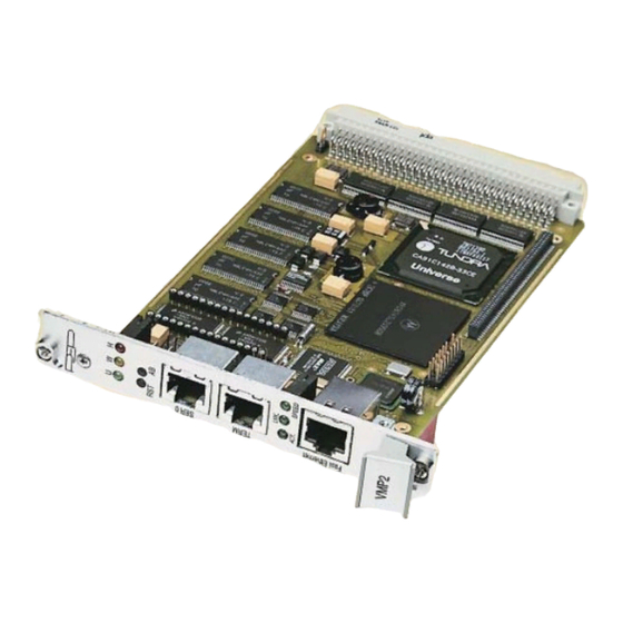
VMP2
PEP Modular Computers VMP2 Manuals
Manuals and User Guides for PEP Modular Computers VMP2. We have
1
PEP Modular Computers VMP2 manual available for free PDF download: Manual
PEP Modular Computers VMP2 Manual (142 pages)
Power PC-based CPU Board for VME Applications
Brand:
PEP Modular Computers
| Category:
Computer Hardware
| Size: 0 MB
Table of Contents
Imprint
2
Table of Contents
3
List of Tables
9
Proprietary Note
15
Trademarks
15
Explanation of Symbols
16
For Your Safety
17
Two Year Warranty
19
Introduction
23
Board Introduction
24
Board Overview
25
VMP2 Main Specifications
26
Applied Standards
28
CE Compliance
28
Mechanical Compliance
28
Environmental Tests
28
Related Publications
28
VME Systems/Boards
28
PMC Add-On Modules/Carriers
28
Functional Description
31
Functional Block Diagram
31
Front Panels
32
Board Layout
33
VMP2 Board (Front View)
33
VMP2 Board (Reverse View)
33
Main Features
34
Cpu
34
MPC8245 (Kahlua II) Features
34
Memory
36
System Memory (DRAM)
36
Flash
36
Eeprom
36
Memory Expansion Socket (DIL600)
36
Board Interfaces
37
VME Interface and Connector Pinout
37
VME Connector CON1
37
VME Bus Connector CON1 Pinout
38
Pin Assignment J1/P1 VME Connector CON1
38
Ethernet Interface and Connector Pinout
39
Ethernet Connector CON8 Pinout
39
Ethernet RJ45 Connector CON8 Pin Assignment
39
Ethernet Connector CON8
39
Serial Interfaces and Connectorpinout
40
Pinouts of Serial Ports (RJ45 Connectors)
40
Serial Port Connectors CON6 and CON7
40
PCI Expansion Interface and Connector Pinout
41
PCI Expansion Connector CON11
41
PCI Expansion Connector (CON11) Pinout
42
PCI Expansion Connector Pinout
42
Serial Interface Expansion Connector and Pinout
44
Serial Interface Expansion Connector CON3 Pinout
44
Serial Interface Expansion Connector (CON3) Pinout
44
Memory Expansion Interface
44
Memory Expansion Connector IC8
44
DEBUG Interface and Connector Pinout
45
Debug Connector CON10 Pinout
45
Digital Temperature Sensor (LM75)
45
Debug Interface Connector (CON10) Pinout
45
DEBUG Connector CON10
45
Special Board Features
46
Watchdog Timer
46
Rtc (Stc M41T56)
46
Reset/Abort
46
Front Panel Led's
47
Installation
51
Board Installation
51
Front Panel I/O Connectors
52
Configuration
55
Jumper Settings
55
Bootstrap Loader / Socket Jumper J1
55
RTC (Real-Time Clock) Calibration Output (J2)
55
Bootstrap Loader / Socket Jumper J1 Settings
55
Resistor Setting for Non-Standard Socket Devices
56
RS485 Termination (Onboard Interface Only)
56
Resistor Setting for Various Non-Standard Socket Devices
56
Jumper Settings for RS485 Termination
56
Pinouts
57
Flash Socket Type Selection
57
Socket Device Selection (Memory Expansion Socket IC8)
57
DIL 32 Pinout for Various Devices
57
Serial Interface Expansion Connector (CON3)
58
RS Expansion Connector Pinout
58
Board Address Map
59
Address Map Overview
59
VMP2 Address Map
59
VME Address Area
60
Onboard Device Addresses
61
VMP2 Device Address Map
61
Special Registers Overview
62
Board Control Registers
62
Board ID Register
62
Software Compatibility ID
63
Memory Configuration Register
64
Flash Bank Select Register
64
Watchdog Control Register
65
Control Register
66
Event Register
67
Board / Logic Revision Register
68
Board Logic / Revision Register
68
UART a / Registers
69
General Register Set (THR/RHR, IER/ISR, MCR/MSR, LCR/LSR, SPR)
69
Baud Rate Register Set (DLL/DLM)
69
Enhanced Register Set
69
UART B / Registers
70
General Register Set (THR/RHR, IER/ISR, MCR/MSR, LCR/LSR, SPR)
70
Baud Rate Register Set (DLL/DLM)
70
Enhanced Register Set
70
IRQ Routing
71
Serial Irq's
71
Real-Time Clock
72
Eeprom
73
Digital Temperature Sensor
73
Netbootloader
75
General Operation
77
Netbootloader Interfaces
77
ABT (Abort) Switch
78
TERM Serial Interface
78
SER0 Serial Interface
78
Ethernet Interface
78
Netbootloader Functions
78
Netbootloader Control
79
System Status Monitoring
79
Netbootloader Control Commands
79
System Status Monitoring Commands
79
Ftp Server Access
80
FLASH Operation
80
Motorola S-Records
80
Ftp Server Commands
80
FLASH Operation Commands
80
Motorola S-Records Commands
80
Operating the Netbootloader
81
Initial Setup
81
Accessing the Netbootloader
81
Netbootloader Configuration
82
Net
82
Passwd
82
Telnet Login
83
FLASH Operations
83
FLASH Offsets
83
Programming an Application
84
Ftp Server Access
84
Motorola S-Records
84
Updating the Netbootloader
85
Updating with an Image Loaded Via an Ftp Server
85
Updating Via a Separate DIL FLASH
85
Uploading a FLASH Area
86
Plug and Play
86
Porting an Operating System to the CPU Board
86
Commands
87
VMP1-IO1 Module (Optional)
106
Overview
107
Board Interfaces
108
Board Layout
109
VMP1-IO1 Front Panel
110
Technical Specifications
111
Board Installation
112
Pinouts
114
Jn1 (CON4) Pin Assignment
114
Jn1, 32-Bit PCI
114
Jn2 (CON5) Pin Assignment
115
Jn2, 32-Bit PCI
115
Jumper Setting
116
VMP1-Post (Optional)
118
Optoisolation RS485 Module (Optional)
122
View of Underside of RS485 Module
123
JTAG Subsystem
125
Serial Port Pinout
131
View of Underside of the CP320-TR1 Module
131
Serial Port Pinout
136
View of Underside of CP320-TR2 Module
136
Advertisement
Advertisement
Related Products
PEP Modular Computers V1553B
PEP Modular Computers VMEM-F1
PEP Modular Computers VMEM-F1-PB1
PEP Modular Computers CP302
PEP Modular Computers Categories
Computer Hardware
Controller
Carrier boards
Network Card
Storage
More PEP Modular Computers Manuals
Login
Sign In
OR
Sign in with Facebook
Sign in with Google
Upload manual
Upload from disk
Upload from URL