Sign In
Upload
Manuals
Brands
Partlow Manuals
Controller
MIC 1161
Partlow MIC 1161 Manuals
Manuals and User Guides for Partlow MIC 1161. We have
1
Partlow MIC 1161 manual available for free PDF download: Operator's Manual
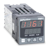
Partlow MIC 1161 Operator's Manual (50 pages)
1/16 DIN MICROBASED LIMIT CONTROLLER
Brand:
Partlow
| Category:
Controller
| Size: 0.14 MB
Table of Contents
Table of Contents
3
Figures & Tables
4
Alarms
5
Process Variable/Setpoint Value Re-Transmission Output
5
Section 1 - General
5
Product Description 1.1
5
Keys and Indicators
6
Installation and Wiring
7
Panel Cut-Out Dimensions
8
Main Dimensions
8
Section 2 - Installation & Wiring
9
Preparation for Wiring
9
Panel Mounting the Controller
9
Wiring Guidelines
9
Installation Considerations
9
Ac Power Wiring
10
Wire Isolation
10
Neutral (for 115 VAC)
10
Use of Shielded Cable
11
Noise Suppression at the Source
11
Inductive Coils
11
Contacts
12
Sensor Placement
13
Thermocouple Lead Resistance
13
Rtd Lead Resistance
14
3 Wire RTD
15
2 Wire RTD
15
Wiring Label
16
AC Power
17
Thermocouple (T/C) Input
17
RTD Input
17
Input Connections 2.3
17
Volt, MV Input
18
Madc Input
18
Remote Reset
18
Remote Digital Communications - RS485
19
Relay Output 2
19
Output Connections 2.4
19
Relay Output 3
20
Madc Output 3 (Recorder Output Only)
20
Section 3 - Configuration & Operation
21
Power up Procedure
21
Keypad Operation
21
Reset Key
21
Operation 3.1
21
Displays
22
Down Key
22
Display Sequence
22
Over-Range/Under-Range Display
23
Front Panel Indicators
24
Setpoint Adjustment
24
Maximum/Minimum Hold
25
Time Exceed
25
Annunciator
26
Configuration 3.2
26
Enable Mode
27
Program Mode
27
Set-Up Mode
27
Default Parameter Indication
28
Display Available
28
Input Filter Time Constant
32
Hysteresis
32
Process Output Upper Value
32
Appendices a - Glossary of Terms
32
Process High Alarm 1 Value
33
Process Low Alarm 1 Value
33
Process High Alarm 2 Value
33
Process Low Alarm 2 Value
33
Logical and of Alarm 1 with Alarm 2
34
Decimal Point
34
Engineering Units Upper
34
Engineering Units Lower
34
Minimum Hold
35
Time Exceeded
35
B - Exploded View & Board Layout
36
Cpu Pwa
37
Option Pwa DC Output 3
38
C - Hardware Definition Code
39
For Thermocouple Inputs
41
For RTD Inputs
41
D - Input Range Codes
41
For DC Inputs
42
E - Specifications
43
Output Specifications
44
Order Matrix
47
F - Model Number Hardware Matrix
47
Software Record/Reference Sheet
48
G- Software Reference
48
Advertisement
Advertisement
Related Products
Partlow MIC 8200
Partlow MIC 2000
Partlow MIC 1400
Partlow MIC 6000
Partlow MRC 7700
Partlow MRC 7000
Partlow MRC 7800
Partlow Categories
Controller
Voice Recorder
Measuring Instruments
More Partlow Manuals
Login
Sign In
OR
Sign in with Facebook
Sign in with Google
Upload manual
Upload from disk
Upload from URL