Sign In
Upload
Manuals
Brands
Parr Instrument Company Manuals
Measuring Instruments
6300
Parr Instrument Company 6300 Manuals
Manuals and User Guides for Parr Instrument Company 6300. We have
1
Parr Instrument Company 6300 manual available for free PDF download: Operating Instructions Manual
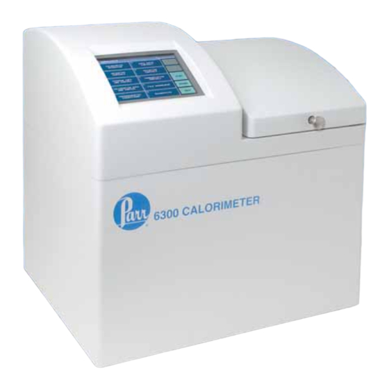
Parr Instrument Company 6300 Operating Instructions Manual (130 pages)
Oxygen Bomb Calorimeter
Brand:
Parr Instrument Company
| Category:
Measuring Instruments
| Size: 2.92 MB
Table of Contents
Table of Contents
3
Preface
7
Scope
7
Explanation of Symbols
8
Intended Usage
8
Fuse
8
General Specifications
9
Environmental Conditions
9
Getting Started
9
Hapter
11
Concept of Operation
11
A Highly Automated Procedure
11
New Convenience and New Technology
11
Isoperibol Operation
11
Dynamic Operation
11
Full Microprocessor Based Process Control
12
Full Microprocessor Based Data Acquisition and Handling
12
Flexible Programming
12
Thermochemical
12
Chapter 2 Installation
13
Required Consumables, Utilities and Power Requirements
13
Installing the Calorimeter
13
Swagelok Tube Fittings
14
General
15
6300 Calorimeter Back Panel
16
6300 Calorimeter External Plumbing
17
Standard
19
Hapter
21
Instrument Description
21
Types of Controls
21
Menu Keys
21
Control Keys
21
Hapter
23
Program Installation & Control
23
Software Installation
23
Default Settings
23
Revising Default Settings
23
6300 Factory Default Settings
24
Figure
24
Bombs
24
Network Data
25
Hapter
27
Operating Instructions
27
To Begin a Test
27
Operating the Oxygen Bomb
27
Figure 5-1 Fill Flow Diagram
28
Allowable Sample Size
29
Attaching the Cotton Thread
29
Cotton Thread Assembly
29
Pre-Period/Post-Period
30
Closing the Bomb
31
Fill Cycle
31
Pre-Period
31
Bomb Firing
31
Rinse & Cool Flow Diagram
32
Post-Period
33
Cool/Rinse
33
Drain
33
Figure 5-5 Drain Flow Diagram
34
Samples
35
Combustion Aids
35
Oxygen Charging Pressure
35
Combustion Capsules
35
Foodstuffs and Cellulosic Materials
36
Coarse Samples
36
Corrosive Samples
36
Explosives and High Energy Fuels
36
Volatile Sample Holders
36
Poor Combustion
37
Combustion Capsule with Adhesive Tape Seal
37
Hapter
39
Reports
39
Entering Corrections and Obtaining the Final Report
39
Manual Entry
39
Fixed Corrections
39
Acid and Sulfur
39
Hapter
41
Reporting Instructions
42
Report Generation
42
Net Heat of Combustion
42
Chapter 8 File Management
43
Clearing Memory
43
Removable SD Memory
43
Chapter Maintenance
45
Troubleshooting
45
Routine Maintenance
45
Inspection of Critical Sealing Surfaces
48
Bomb Exhaust Troubleshooting
48
Jacket Fill and Cooling Problems
50
Bomb Removal and Replacement
51
6300 Calorimeter Error List
51
Appendix A Menu Operating Instructions
53
Main Menu
53
Calorimeter Operation Menu
53
Ppendix
53
Temperature Vs. Time Plot
54
Temperature Plot Setup Menu
54
Operating Controls Menu
55
Data Entry Controls Menu
59
Appendixa
53
Appendix B Calculations
60
Run Data File Manager
67
Diagnostics Menu
70
Calculating the Heat of Combustion
71
Fuse Correction
71
General Calculations
71
Standardizing the
71
Thermochemical Corrections
71
Acid and Sulfur Corrections
73
ASTM Treatment for Acid and Sulfur
74
Table
74
Settings for ISO & BSI Methods
74
Conversion to Net Heat of Combustion
75
ISO Calculations
75
Spiking Samples
75
Appendix C
77
Standardizing the Calorimeter
77
Standard Materials
77
Operation
77
Automatic Statistical Calculations
78
Calorimeter Control Limit Values in J/G When Benzoic Acid Is Used as a Test Sample
78
Calorimeter Control Limit Values in Cal/G When Benzoic Acid Is Used as a Test Sample
79
Calorimeter Control Limit Values in Btu/Lb When Benzoic Acid Is Used as a Test Sample
80
Appendixc C Standardization
77
Appendix D Communications Interfaces
81
USB Port
81
Balance and Port Input Driver Specifications
81
Sartorius Balance Interface
81
Connection
81
Table
81
Generic Interface
82
6300 Data File Naming Convention
82
6300 Calorimeter Run Data Template
82
Ethernet Interface
83
Samba Server Feature (Optional)
84
Bar Code Port
92
Network Data Services
92
Appendixd
81
Appendix E Technical Service
93
Return for Repair
93
Ppendix
93
Appendix F Drawings
96
A1250DD2 Controller Assembly
96
A1251DD Oxygen Solenoid Assembly
96
A1252DD Water Solenoid Assembly
96
A1257DD Water Regulator Assembly
97
A1258DD Temperature Control Assembly
97
A1260DD Water Level Assembly
97
A1264DD Air Can Assembly
98
A1265DD Bucket and Stirrer Tube Assembly
99
Parts Diagram for the 1136 and 1136CL Oxygen
102
Parts Diagram for the 1138 and 1138CL Oxygen
104
6300 Oxygen Bomb Calorimeter Cutaway Right
106
Figure F
106
6300 Oxygen Bomb Calorimeter Cutaway Left
107
6300 Oxygen Bomb Calorimeter Cover Open
108
A1250DD2 Control Schematic
109
A1251DD Oxygen Solenoid Assembly
110
A1200DD Internal Plumbing Diagram
111
A1252DD Water Solenoid Assembly
112
A1416DD Bomb Wash Pump Assembly and Fittings
113
A1254DD Circulatory Pump Assembly
114
A1255DD Bucket Stirrer Assembly
115
A1256DD Water Assembly Tank
116
A1257DD Water Regulator Assembly
117
A1258DD Temperature Control Assembly
118
Cover Contact Pin Assembly
119
Stirrer Motor and Mount
120
A1260DD Water Level Control Assembly
121
A1265DD Bucket Assembly
122
6300 Air Can Assembly
123
A1450DD Bomb Head Assembly (1)
124
A1450DD Bomb Head Assembly (2)
125
Appendix G Bomb Rinse Container Assembly
127
Overview
127
Concept of Operation
127
Bombs
128
Vessel Rinse Container
128
Figure G
128
Appendixg
127
Advertisement
Advertisement
Related Products
Parr Instrument Company Categories
Measuring Instruments
More Parr Instrument Company Manuals
Login
Sign In
OR
Sign in with Facebook
Sign in with Google
Upload manual
Upload from disk
Upload from URL