Sign In
Upload
Manuals
Brands
Paccar Manuals
Measuring Instruments
SM001-300
Paccar SM001-300 Manuals
Manuals and User Guides for Paccar SM001-300. We have
1
Paccar SM001-300 manual available for free PDF download: Service Manual
Paccar SM001-300 Service Manual (39 pages)
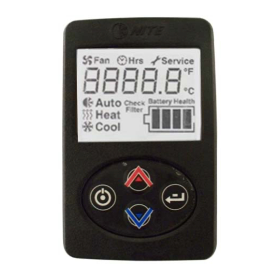
Kenworth Idle Management System
Brand:
Paccar
| Category:
Measuring Instruments
| Size: 2 MB
Table of Contents
Table of Contents
2
General Safey Instructions
5
Warnings, Cautions, and Notes
5
Precautions for Working with Hfc134A (R134A) Refrigerant and Polyvinyl Ether (PVE) Refrigerant Oil
5
Important Safety Notices
6
External Component Identification and Location
8
Fuses
8
Figure 1. Fuses and Relays
8
Figure 2. Fuses and Relays (Units Built 8/1/2016 to Present)
8
Relays
9
Fan and Temperature Control Display LED Display
9
System and Compressor Controller
9
Figure 3. Fan and Temperature Control Display
9
Figure 4. System and Compressor Controller
9
Linear Power Module
10
Discharge Temperature Sensor - Freeze Switch
10
Evaporator Blower
10
Condenser Fan
10
Battery Management System (BMS)
10
Battery Separator
10
Figure 5. Linear Power Module
10
Figure 6. Discharge Temperature Sensor
10
Figure 7. Evaporator Blower and Condenser Fan
10
Figure 8. Battery Management System
10
Figure 9. Battery Separator Solenoid, Located in the Battery Box
11
Figure 10. Automated Battery Disconnect Solenoid, Located in the Battery Box
11
Internal Components
12
High Pressure Switch
12
Compressor
12
Thermal Limit Switch on Compressor
12
Evaporator Inlet Filter
12
Figure 11. High Pressure Switch
12
Figure 12. Compressor
12
Figure 13. Thermal Limit Switch on Compressor
12
Figure 14. Evaporator Inlet Filter
12
Figure 18. Internal Wiring Diagram (before 8/1/2016)
13
Figure 19. External Wiring Diagram
13
A/C System Diagnostic
13
ESPAR Heating System Diagnostic Table
16
Appendix
18
Battery Condition and Performance
18
Fan and Temperature Control Display
18
Relay Testing
18
Pressure Switch Testing
18
Figure 15. Relay Testing
18
Check Continuity Across Fuse Body
19
Discharge Temperature Sensor/Freeze Switch Testing
19
Compressor Thermal Limit Switch
19
Main Controller/Compressor Controller
19
Condenser Fan Motor Testing
20
Evaporator Blower Motor and Linear Power Module Testing
20
Compressor Rubber Mounts
20
Testing the Battery Management System (BMS)
21
Can Bus
22
Testing the Espar Heater Connected to the EHVAC Digital Controller
22
Connecting the System
23
Figure 16. Service Equipment
23
Evacuating the System
24
Figure 17. Service Recovery Connections
24
Charging the Kenworth EHVAC System
25
Figure 20. Wiring Diagram (8/1/2016 to Present)
30
Service Instructions for Ring Terminal / Controller and Compressor
33
Operation
37
Figure 21. On/Off Button
37
Figure 22. Changing Mode
37
Figure 23. Changing Blower Speeds
37
Figure 24. Changing Temperature
37
Figure 25. View System Runtime/Hours
38
Figure 26. Change from °F to °C
38
Figure 27. Enter Service Mode
38
Figure 28. Service Screens
39
Figure 29. EHVAC Filter
39
Advertisement
Advertisement
Related Products
Paccar SmartAir eHVAC System
Paccar Categories
Winches
Trucks
Engine
Battery Charger
Automobile Battery Charger
More Paccar Manuals
Login
Sign In
OR
Sign in with Facebook
Sign in with Google
Upload manual
Upload from disk
Upload from URL