Table of Contents
Advertisement
S
ERVICE
M
ANUAL
Kenworth Idle Management System
Confidentiality Notice: This document and the information contained herein is proprietary. It shall not be reproduced, copied or disclosed,
in whole or in part, or used for manufacture without the written permission of PACCAR. You are hereby notified that any dissemination of
this information is strictly prohibited.
Technical Information and Diagnostic Guide
This guide will assist you in becoming more familiar with the working components
of the Kenworth Idle Management System and the proper steps and procedures to
completely diagnose the Kenworth Idle Management System unit.
©2016 PACCAR Corporation
HVAC
Section
Title
Idle Management System Service Manual
SM001-300
Number
Date
Rev. 9 © 9/2016
Model
All w/ Idle Management System
Page
1 of 39
Advertisement
Table of Contents

Summary of Contents for Paccar SM001-300
- Page 1 Confidentiality Notice: This document and the information contained herein is proprietary. It shall not be reproduced, copied or disclosed, in whole or in part, or used for manufacture without the written permission of PACCAR. You are hereby notified that any dissemination of...
-
Page 2: Table Of Contents
HVAC: Idle Management System Page 2 of 39 Number SM001-300 Contents GENERAL SAFEY INSTRUCTIONS ........5 Warnings, Cautions, and Notes . - Page 3 Page 3 of 39 Number SM001-300 Condenser Fan Motor Testing ........20 J.
- Page 4 HVAC: Idle Management System Page 4 of 39 Number SM001-300 List of Figures Figure 1. Fuses and Relays ..............8 Figure 2.
-
Page 5: General Safey Instructions
HVAC: Idle Management System Page 5 of 39 Number SM001-300 GENERAL SAFEY INSTRUCTIONS CAUTION A number of alerting messages are in this manual. Please read and follow them. They are there for your pro- • The air conditioning system uses HFC134a tection and information. -
Page 6: Important Safety Notices
HVAC: Idle Management System Page 6 of 39 Number SM001-300 • Do not wear loose-fitting or torn clothing. Remove all jewelry before working. NOTE • Before beginning any repair, disconnect the battery (negative [-] cable) from both battery boxes and dis- Take care to follow the handling procedures below: charge any capacitors. - Page 7 HVAC: Idle Management System Page 7 of 39 Number SM001-300 • Do not perform any repair when impaired, tired, • Close the manual fuel valves prior to performing fatigued or after consuming alcohol or drugs that can maintenance and repairs, and when storing the vehi- impair your functioning.
-
Page 8: External Component Identification And Location
HVAC: Idle Management System Page 8 of 39 Number SM001-300 EXTERNAL COMPONENT IDENTIFICATION AND LOCATION A. Fuses Figure 2. Fuses and Relays (Units built 8/1/2016 to Present) F1 Fuse 10 Amp (Mini) This fuse provides short circuit protection for the System control. -
Page 9: Relays
HVAC: Idle Management System Page 9 of 39 Number SM001-300 Location: on the control center. F3 Fuse 20 Amp (Mini) This fuse provides short circuit protection for the evapo- rator blower. Location: on the control center. F4 Fuse 60 Amp (Maxi) This fuse provides short circuit protection for the com- pressor. -
Page 10: Linear Power Module
HVAC: Idle Management System Page 10 of 39 Number SM001-300 E. Linear Power Module This module controls the amount of voltage delivered to the evaporator blower creating variable blower speeds. It is located in the return air in front of the evaporator coil. -
Page 11: Figure 9. Battery Separator Solenoid, Located In The Battery Box
HVAC: Idle Management System Page 11 of 39 Number SM001-300 Automated Battery Disconnect (Option) This device disconnects the EHVAC batteries from the EHVAC unit when the cab disconnect switch is set to OFF. The cab disconnect switch must be set to ON for the EHVAC unit to operate. -
Page 12: Internal Components
HVAC: Idle Management System Page 12 of 39 Number SM001-300 INTERNAL COMPONENTS A. High Pressure Switch This normally closed brazed pressure switch will open and prevent the operation of the compressor due to high internal pressure. It is NOT serviceable. -
Page 13: A/C System Diagnostic
HVAC: Idle Management System Page 13 of 39 Number SM001-300 A/C System Diagnostic Check service screens before troubleshooting, see NOTE “Operation” on page 37. Removing fuse F1 for 10-15 seconds will reset the sys- tem controller to factory default settings. - Page 14 HVAC: Idle Management System Page 14 of 39 Number SM001-300 Table 1. A/C System Diagnostic PROBLEM POSSIBLE CAUSE CORRECTIVE ACTION “Appendix” on page 18. Unit runs—but does not 1. Airflow blockage. 1. Clear any blockage from recirculation grill or louvers.
- Page 15 HVAC: Idle Management System Page 15 of 39 Number SM001-300 Table 1. A/C System Diagnostic PROBLEM POSSIBLE CAUSE CORRECTIVE ACTION “Appendix” on page 18. Unit runs correctly, but 1. Ground terminal(s). 1. Inspect and tighten ALL connections. less than expected run 2.
-
Page 16: Espar Heating System Diagnostic Table
HVAC: Idle Management System Page 16 of 39 Number SM001-300 ESPAR Heating System Diagnostic Monthly running and periodic maintenance are required for proper heater operation and performance. Table Check service screens before troubleshooting, see “Operation” on page 37. Table 2. - Page 17 HVAC: Idle Management System Page 17 of 39 Number SM001-300 Table 2. ESPAR Heating System Diagnostic Table PROBLEM POSSIBLE CAUSE CORRECTIVE ACTION / “Appendix” on page 18. Heater blows cold air but no 1. Fuel. See Espar Manual. heat. 2. Fuel pump.
-
Page 18: Appendix
HVAC: Idle Management System Page 18 of 39 Number SM001-300 Appendix Now, with relay unplugged, check across terminals 85 and 86 of the relay, using an OHM meter. You should have approximately 90 ohms + or - 10% at 68°F (20°C). -
Page 19: Check Continuity Across Fuse Body
HVAC: Idle Management System Page 19 of 39 Number SM001-300 connection, high pressure situation or defective switch. If H. Main Controller/Compressor Controller the pressure, harness and connections are okay, the EHVAC unit will have to be replaced. See updated information on “Service Instructions for Ring... -
Page 20: Condenser Fan Motor Testing
HVAC: Idle Management System Page 20 of 39 Number SM001-300 e. If all signals are correct and the safety controls Using a DC ammeter you can check the amperage draw thermal limit on compressor, high pressure of the blower. Normal amps approximately 5–10 depend- switch and temp sensor /freeze switch are okay, ing on speed requests. -
Page 21: Testing The Battery Management System (Bms)
HVAC: Idle Management System Page 21 of 39 Number SM001-300 L. Testing the Battery Management System With aux voltage okay, LED flashing and 12 volts across pins 8 and 1, start the truck or connect the start batteries (BMS) to a battery charger and bring the voltage above 13.2 for at least 15 seconds. -
Page 22: Can Bus
HVAC: Idle Management System Page 22 of 39 Number SM001-300 If the separator switch tests okay, reconnect the separa- If not, check at BMS. Disconnect harness at BMS. tor wires, unplug the BMS for at least 15 seconds, recon- Check pins 6 and 7 on the BMS. You should measure nect BMS and repeat BMS test. -
Page 23: Connecting The System
HVAC: Idle Management System Page 23 of 39 Number SM001-300 does not operate, the problem is internal in the heater. See Espar’s Airtronic Installation, Troubleshooting, and CAUTION Parts Manual for complete heater diagnostics. The Kenworth EHVAC uses PVE lubricant in the refrig- If the resistance level is not present or correct, check erant system. -
Page 24: Evacuating The System
HVAC: Idle Management System Page 24 of 39 Number SM001-300 On the recovery station and hose fittings, verify that 3. Connect the recovery stations blue hose to the ser- all valves are closed. The valves at the recovery sta- vice port located on the Kenworth EHVAC system. -
Page 25: Charging The Kenworth Ehvac System
HVAC: Idle Management System Page 25 of 39 Number SM001-300 c. Continue to operate the recovery station vacuum pump until the system has pulled a vacuum of NOTE 750 – 1000 microns as measured by the elec- tronic vacuum gauge (15 minutes minimum). - Page 26 HVAC: Idle Management System Page 26 of 39 Number SM001-300 1. Determine the model of truck to charge the A/C sys- 2. On the recovery station, set the high side valve to tem. CLOSED, and the low side valve to CHARGE.
- Page 27 HVAC: Idle Management System Page 27 of 39 Number SM001-300 Table 4. Discharge Sensor / Freeze Switch Testing Chart...
- Page 28 Page 28 of 39 Number SM001-300 HVAC: Idle Management System 12 VOLTS (RED) GND (BLACK) CANL (GREEN) CANH (YELLOW)
- Page 29 Page 29 of 39 Number SM001-300 HVAC: Idle Management System ACCESSORY INPUT TO UNIT HEATER_EN (BLACK) IGNITION INPUT TO UNIT GROUND (WHITE) VEHICLE WEBASTO HEATER_LVL (BLUE) FUEL OPERATED HEATER DEUTSCH DT06-4S FUSE AMP 929504-2 WEBASTO OPTION HEATER_OPTION (RED) HEATER_EN (YELLOW)
-
Page 30: Figure 20. Wiring Diagram (8/1/2016 To Present)
Page 30 of 39 Number SM001-300 HVAC: Idle Management System BLOWER MOTOR OUTPUT + MOTOR OUTPUT - BLOWER SYSTEM COMPRESSOR OVERTEMP CUT OUT CONTROLLER COMPRESSOR LPM1 MOTOR OUTPUT + PRESS IN W23-RED-14 MOTOR OUTPUT - HIGH W24-BLACK-14 PRESSURE SWITCH LINEAR... - Page 31 HVAC: Idle Management System Page 31 of 39 Number SM001-300 Table 5. Control Module Pinout with Functional Information Circuit ID Wire Color Function Typical Voltage Other End of Circuit CONTROL_F Red/White 12V power from F1 - 12-14V Control fuse F1 and control pin 1...
- Page 32 HVAC: Idle Management System Page 32 of 39 Number SM001-300 Table 5. Control Module Pinout with Functional Information Circuit ID Wire Color Function Typical Voltage Other End of Circuit WAKEUP Blue Switch to Ground input 9-14V with control off, Blue wire (pin 6) in connector from ACU - turns on <1V when unit on...
-
Page 33: Service Instructions For Ring Terminal / Controller And Compressor
HVAC: Idle Management System Page 33 of 39 Number SM001-300 Service Instructions for Ring Terminal / Controller and Compressor WARNING: To avoid potential property damage or personal injury, Read Important Safety Warnings and ALL instructions before attempting to install or service product. - Page 34 HVAC: Idle Management System Page 34 of 39 Number SM001-300 WARNING: To avoid potential property damage or personal injury, Read Important Safety Warnings and ALL instructions before attempting to install or service product. CAUTION: Care must always be taken to install the control cover without bending the connector pins identified in FIGURE 1.
- Page 35 HVAC: Idle Management System Page 35 of 39 Number SM001-300 WARNING: To avoid potential property damage or personal injury, Read Important Safety Warnings and ALL instructions before attempting to install or service product.
- Page 36 HVAC: Idle Management System Page 36 of 39 Number SM001-300 WARNING: To avoid potential property damage or personal injury, Read Important Safety Warnings and ALL instructions before attempting to install or service product.
-
Page 37: Operation
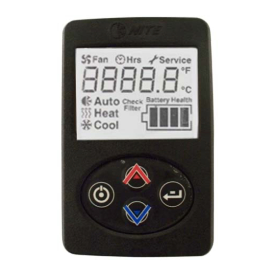
HVAC: Idle Management System Page 37 of 39 Number SM001-300 Operation To start the system push ON/OFF button. Display will show current mode/ temperature setting / battery level. See Figure 21. Initial default setting is blower speed 1/ AUTO- MODE /60 °F. -
Page 38: Figure 25. View System Runtime/Hours
HVAC: Idle Management System Page 38 of 39 Number SM001-300 To enter SERVICE MODE: Push both the ON/OFF and ENTER button simultaneously at any time. See Figure Display will show service indicator and code 00 unless a fault has occurred. If there is an active fault the display will show it as 01, 02 or 03. -
Page 39: Hvac: Idle Management System
HVAC: Idle Management System Page 39 of 39 Number SM001-300 Press the ENTER button to proceed through the avail- When necessary, Check Filter light will notify you that the able service screens. See Figure 28. EHVAC filter must be cleaned or changed. To reset filter: at screen 1 press and hold enter button for 3 seconds.
Need help?
Do you have a question about the SM001-300 and is the answer not in the manual?
Questions and answers