Sign In
Upload
Manuals
Brands
Oxford Instruments Manuals
Power Supply
NanoScience MercuryiPS
Oxford Instruments NanoScience MercuryiPS Manuals
Manuals and User Guides for Oxford Instruments NanoScience MercuryiPS. We have
1
Oxford Instruments NanoScience MercuryiPS manual available for free PDF download: Operator's Manual
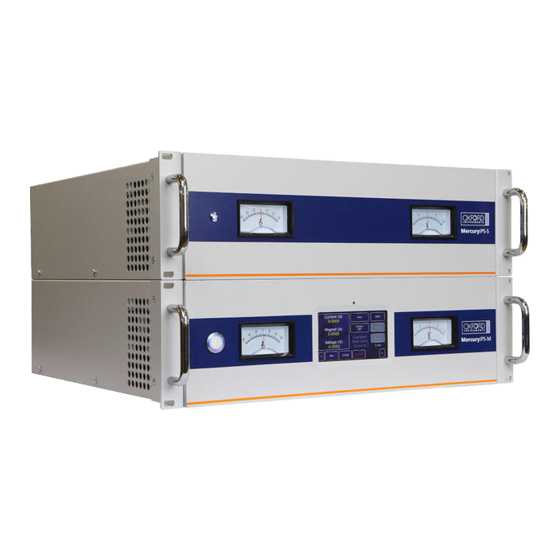
Oxford Instruments NanoScience MercuryiPS Operator's Manual (169 pages)
Power Supply for Superconducting Magnets
Brand:
Oxford Instruments
| Category:
Power Supply
| Size: 6 MB
Table of Contents
Table of Contents
2
Preface
10
Use of this Manual
10
Customer Support
13
Health and Safety Information
14
Disclaimers
15
Acknowledgements
15
Acronyms
16
Certification Compliance Statements
17
About Oxford Instruments
18
1 Health and Safety
19
Warnings
19
Protective and Functional Ground
19
High Voltage Hazard
20
Maintenance and Adjustment
20
Restrictions on Use
20
Cautions
21
Electrostatic Caution
21
Cooling Caution
21
Acoustic Noise Caution
22
Solid Waste
22
2 Mercury Ips Basics
23
Mercuryips Front and Rear Panels
24
Electrical Power Supply
25
Temperature Sensor Circuits
26
Remote Interfaces
27
Main Components
28
Chassis
29
Power Supply
29
User Interface
29
Motherboard
30
Magnet Control Board
32
Filter Board
32
Run-Down Resistors
32
Alarms and Interlocks
33
3 Getting Started
34
Checking the Electrical Supply
34
Mounting the Equipment
34
Background Magnetic Field
35
Connecting Electrical Power
35
Powering up the Mercuryips for the First Time
36
The Mercuryips Touch Screen
36
The Magnet Home Page
37
Custom Home
39
Channel Summary Widget
39
Drop-Down Menus
39
Scrolling
40
Soft Keypads
40
Using Arrows to Adjust Integer Values
43
Button Labels
43
Common Touch Screen Features
43
Setting the Date and Time
44
Plotting Signals on the Mercuryips Touch Screen
45
Plot Configuration
45
Scaling a Plot
47
4 How to Configure the Ips for Your Magnet
49
Quench
50
Slaves Detected
51
Magnet Type
52
Config
53
The Configuration Table (Figure 9)
53
Limit(A)
56
Limit(V)
56
I to H (A/T)
57
Ind (H)
57
Sw Cur (Ma)
57
Switch
57
Trans (Ms)
57
Mode
58
Safety
58
Limit (K)
59
Limit (L)
59
Sw Intel
59
Htr Res ()
60
Lead ()
60
Sw Res ()
60
Catch
61
Epsilon (A)
61
SW off (Ms)
61
SW on (Ms)
61
5 Operating the Magnet
62
Rate Limits
63
Fast Rates / Slow Rates
66
Editing the Rate Limits Table
66
Quench
66
Vector Rotate Mode
67
6 Temperature Measurement
69
Sensor Connections
69
Connecting Thermocouples
70
Configuring a Temperature Sensor
70
Configuring the Sensor Details
71
To Clear a Widget Configuration
73
Using a Generic Calibration-File
74
Overview
74
Adjusting a Generic Calibration File
74
Types of Temperature Sensor
76
Thermocouples
76
Metallic Resistance Thermometers (Positive Temperature Coefficient)
76
Semiconductor Resistance Thermometers (Negative Temperature Coefficient)
76
Semiconductor Diodes
77
Excitation Current
77
Calibration for Different Sensors
78
Available Generic Calibration Files
79
More about Thermocouples
80
Thermocouple Principles
80
Configuring for Thermocouples
80
Reference Junction Compensation
82
External Reference Junctions
82
7 Cryogen Level-Meter
84
Principles of Operation
84
Operation of the Board with a Helium-Level Probe
84
Operation of the Board with a Nitrogen-Level Probe
85
Why Different Methods Are Used for the Two Liquids
85
Installing the Level-Meter Board
85
Removing the Top Cover
85
Fitting the Board
86
Basic Check of Board Operation
88
Connecting the Level Probe
88
Configuring Mercuryips for Helium Level Meter
88
Configuring Mercuryips for Nitrogen Level Meter
90
8 Managing Your Mercury
93
General
93
Display
95
Devices
97
Clock
98
File Transfer
99
Updates
100
Access Level
102
Factory
104
Save File
105
Load File
106
9 Remote Operation
107
Remote Operation Using RS232 or ISOBUS
107
Configuring RS232 and Isobus
107
Serial RS232 Cabling Requirements
109
Remote Operation Using GPIB
110
Configuring GPIB
110
GPIB Cabling Requirements
111
Remote Operation Using Ethernet
111
Configuring Ethernet
111
Ethernet Cabling Requirements
113
Remote Operation Using USB
113
Configuring USB
113
USB Cabling Requirements
113
USB Drivers
113
Switching Mercuryips Control between Local and Remote
114
Testing Remote Connections
114
Programming Examples
114
10 Command Reference Guide
116
Nomenclature Used in this Section
116
SCPI and Legacy Command Sets
116
SCPI Commands
116
SCPI Protocols
117
Reading the Instrument Identity
117
Basic SCPI Command Structure
118
Verbs
118
Nouns
119
Invalid Responses
129
Legacy Commands
129
Legacy Command Protocols
129
Legacy Monitor Commands
129
Legacy Control Commands
132
Legacy System Commands
133
11 Temperature Sensor Daughter Board
134
Overview of the Temperature Sensor Board
134
Installing a Temperature Sensor Board
134
Fitting the Board
134
Basic Check of Board Operation
135
Circuit Description of the Temperature Sensor Board
135
Voltage Measurement Mode
135
Resistance Measurement in Constant Current Mode
137
Resistance Measurement in Constant Voltage Mode
138
Calibrating the Temperature Measurement Circuit
139
12 Auxiliary I/O Daughter Board
141
Description of the Auxiliary I/O Board
141
Auxiliary I/O Board Functions
141
Gas-Flow Control Using a Motorised Needle-Valve
142
Installing an Auxiliary I/O Board
142
Fitting the Board
142
Basic Check of Board Operation
142
Connecting to the Auxiliary I/O Board
143
Configuring an Input on the Auxiliary I/O Board
143
Configuring an Output on the Auxiliary I/O Board
144
13 Pressure Board
146
Description of the Pressure Board
146
Description of the Pressure Board Circuit
146
Installing a Pressure Board
149
Fitting the Board
149
Basic Check of Board Operation
149
Connecting to the Pressure Board
149
Configuring the Pressure Board
151
Configuring the Pressure Sensor Details
151
14 Gpib Daughter Board
154
Description of the GPIB Daughter Board
154
Installing a GPIB Board
154
Fitting the Board
154
Basic Check of Board Operation
154
Connecting to the GPIB Board
155
15 Preventive Maintenance
156
Cleaning the Touch-Screen
156
Calibrating the Temperature Sensor Circuits
156
Lubricating the Fan
156
Lithium-Ion Coin Cell Replacement
157
16 Alarms, Interlocks and Troubleshooting
158
Alarms and Interlocks
158
Alarm Logs and Alarms History
158
Troubleshooting
161
Internal Faults
161
External Faults
161
Directory of Alarms
162
17 Technical Specifications
165
Physical Specification
165
Electrical Power Supply
165
Magnet Outputs
165
Sensor Inputs
166
PC Interfaces
167
Electrical Isolation
167
Environmental Specifications
167
Level Meter Board
168
Pressure Board
168
18 Customer Support
169
Advertisement
Advertisement
Related Products
Oxford Instruments NanoScience Optistat DN-V
Oxford Instruments NanoScience Optistat CF
Oxford Instruments Andor Neo 5.5 sCMOS
Oxford Instruments Shasta
Oxford Instruments TC948
Oxford Instruments Categories
Laboratory Equipment
Digital Camera
Industrial Equipment
Power Supply
Security Camera
More Oxford Instruments Manuals
Login
Sign In
OR
Sign in with Facebook
Sign in with Google
Upload manual
Upload from disk
Upload from URL