Sign In
Upload
Manuals
Brands
Oxford Instruments Manuals
Controller
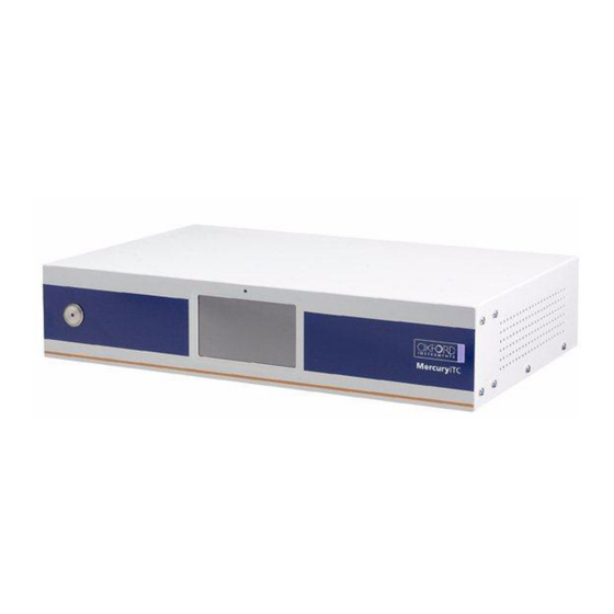
Mercury iTC
Oxford Instruments Mercury iTC Manuals
Manuals and User Guides for Oxford Instruments Mercury iTC. We have
1
Oxford Instruments Mercury iTC manual available for free PDF download: Handbook
Oxford Instruments Mercury iTC Handbook (146 pages)
Brand:
Oxford Instruments
| Category:
Controller
| Size: 3 MB
Table of Contents
Table of Contents
3
Preface
9
Use of this Manual
9
Customer Support
9
Health and Safety Information
10
Intended Users
10
Statement of Intended Use of the Mercury Itc
10
Typographical Conventions
11
Disclaimers
11
Copyright Notice
11
Acknowledgements
12
Acronyms, Abbreviations and Special Terms
12
Revision History
12
Certification Compliance Statements
13
Health and Safety
15
Warnings
15
Protective Ground
15
High Voltage Hazard
15
Maintenance and Adjustment
16
Restrictions on Use
16
Cautions
16
Electrostatic Caution
16
Cooling Caution
17
Solid Waste
17
Overview of the Itc
19
System Description
20
Temperature Sensor Circuits
21
Heater Circuits
21
Optional Cooling Circuit
21
Remote Interfaces
21
Display and Touch-Screen
21
Electrical Power Supply
22
User Interface
23
Front and Rear Panel Controls
23
LCD Display and GUI
23
Using the Touch Screen
23
Initiating Actions
23
Drop-Down Menus
23
Scrolling
24
Soft Keypads
25
Using Arrows to Adjust Integer Values
27
Button Labels
27
Common Screen Features
28
Home and Apply Buttons
28
Home Page
28
Channel Summary Panel
29
Channel Display Configuration Page
30
Device Pair Configuration Page
31
Sensor Details
32
Temperature Sensor Details Page
32
Generic Sensor Adjustment Page
33
Level Meter Sensor Details Page
34
Plot Configuration Page
36
Plot Page
37
Adjusting the Plot Scaling
37
Control Loop Configuration Page
38
Gas Flow Configuration Page
40
PID Table Editor Page
41
General Settings Tab
43
Display Settings Tab
44
Card Settings Tab
45
RS232 Settings Tab
46
Ethernet Settings Tab
47
Isobus Settings Tab
48
GPIB Settings Tab
48
Clock Settings Tab
49
Cal Update Settings Tab
50
F/W Update Settings Tab
51
3.2.12.10 Engmode Tab
52
3.2.12.11 Factory Settings Tab
53
Alarm Logs Page
54
Heater Configuration Page
55
Sweep Table Page
56
Save File Pages
57
Load File
58
Functional Description
59
Main Components
59
User Interface
60
Motherboard
60
Itc Connections
60
Electrical Power Connection
60
Temperature Sensor Inputs
60
Outputs
60
Heater and Sensor Connections
61
Connecting Thermocouples
61
Communications Interfaces
61
Serial RS232 Interface
62
Oxford Instruments Nanoscience ISOBUS
63
USB Interface
63
Ethernet Interface
63
Daughter Boards
63
Expansion Slots
64
Positioning Daughter Boards
64
Interconnecting Heater and Temperature-Sensor Boards
65
Overview of Temperature Measurement
66
Measurement Principles
66
Types of Temperature Sensor
66
Thermocouples
68
Resistance and Diode Sensors
68
Calibration for Different Sensors
68
Circuit Descriptions
69
Temperature Measurement Circuit
69
Description of Voltage Measurement Mode
69
Description of Constant Current Measurement Mode
70
Description of Constant Voltage Measurement Mode
71
Calibrating the Temperature Measurement Circuit
73
Heater Circuit
74
Description of the Heater Circuit
74
Calibrating the Heater Circuit
75
Getting Started
77
Checking the Electrical Supply
77
Mounting the Equipment
77
Connecting Electrical Power
78
Connecting the Heaters and Sensors
78
Connecting the Data Interfaces
78
Connecting the Ethernet Interface (if Required)
78
Connecting the RS232 Serial Interface (if Required)
78
Connecting ISOBUS (if Required)
78
Connecting the GPIB (if Required)
79
Connecting the Auxiliary Port (if Required)
79
Connecting the Level-Meter (if Required)
79
Powering up the Unit for the First Time
80
Setting the Date and Time
80
Configuring the Inputs
81
Configuring the Sensor Details
81
Using a Generic Calibration-File
81
Configuring a Heater
82
Configuring the Heater Control Loop
83
Configuring Manual Heater Control
83
Configuring Automatic Heater Control
83
Configuring a Gas Valve
84
Configuring Manual Control of the Gas Valve
84
Configuring Automatic Control of the Gas Valve
85
Testing the Inputs and Outputs
85
Testing the Temperature Sensor Inputs
85
Testing the Heater Output
85
Configuring Remote Interfaces
85
Basic Operating Instructions
87
Configuring the LCD Display
87
Changing a Setpoint
87
Changing a Heater Setpoint
87
Changing a Gas-Flow Setpoint
87
Using the Sweep Function
87
The Purpose of the Sweep Function
87
Programming a Sweep
88
Loading a Sweep
88
Starting a Sweep
88
Stopping a Sweep
89
Using the Plot Function
89
Configuring a Plot
89
To Remove a Trace from the Plot
90
To Exit the Plot
90
Configuring External Interfaces
90
Configuring the Ethernet Interface (if Required)
90
Configuring the RS232 Serial Interface (if Required)
91
Configuring the GPIB (if Required)
91
Configuring the USB Interface (if Required)
91
Enabling Remote Control of the Itc
91
Enabling Local Control of the Itc
92
Re-Configuring Sensors and Heaters
92
To Clear a Panel Configuration
92
Re-Configuring a Sensor
92
Re-Configuring a Heater
92
Re-Configuring a Control Loop
92
Changing Control-Loop Parameters
93
Entering PID Parameters Manually
93
Creating a PID Table
93
Remote Operation
95
Notes on Instrument Addresses
95
Communication Protocols for RS232 and GPIB
95
Commands and Responses
96
Numeric Parameters
96
Control Via ISOBUS
96
GPIB Interface
97
Switching between RS232 and GPIB Operation
97
Sending Commands Via the GPIB
97
Accepting Responses Via the GPIB
98
Status Byte and Use of a Serial Poll
98
RQS Bit
98
BAV Bit
98
MAV Bit
98
Status Byte Update Rate
99
Use of the Service Request Line
99
Use of the Device Clear Function
99
Use of the Interface Clear Function
99
Non-Implemented Features of the GPIB
99
Compatibility with IEEE-488.2
100
Writing a Reliable GPIB Control Program
100
Timeouts
100
Preventive Maintenance
101
Six-Monthly Maintenance
101
Cleaning the Touch-Screen
101
Calibrating the Temperature-Sensor Circuits
101
Unscheduled Maintenance
101
Troubleshooting
103
Fault-Finding Features of the Itc
103
The Alarm-Logs
103
Troubleshooting Information
103
Command Reference Guide
105
Nomenclature Used in this Section
105
SCPI and Legacy Command Sets
105
SCPI Command Messages
105
SCPI Protocol Conventions
105
Command Structure
106
Verbs
106
Nouns
106
System Commands
107
Addressing a Temperature Sensor
108
Addressing a Heater Controller
110
Addressing a Level Meter Sensor
110
Addressing an Auxiliary I/O Daughter Board
112
Addressing a Control Loop
113
Invalid Responses
113
Legacy Command Messages
113
Technical Specifications
115
Physical Specification
115
Electrical Power Supply
115
Sensor Inputs
115
Heater Outputs
116
PC Interfaces
116
Electrical Isolation
117
Environmental Specifications
117
Theory of Control Loops
119
General Information on Control Loops
119
General Information on Temperature Control Loops
119
Open Loop Operation
120
On-Off Control
120
Proportional Control
121
Proportional Control with Integral Action
122
Proportional Control with Integral and Derivative Action
123
North American Terminology
123
PID Tables
124
PID Table Operation
124
Entering a PID Table
124
Theory of Gas-Flow Control
125
Overview of Gas Control
125
Manual Control of the Gas Flow
125
Automatic Control of the Gas Flow
125
Heater Target Tables
126
Temperature Sensor Daughter Board
127
Overview of the Temperature Sensor Board
127
Installing a Temperature Sensor Board
127
Fitting the Board
127
Connecting the Sensor
128
Configuring the Temperature Sensor Board
128
Heater Daughter Board
129
Overview of the Heater Board
129
Installing a Heater Board
129
Fitting the Board
129
Connecting the Heater
130
Configuring the Heater Board
130
Configuring the Control Loop
130
Auxiliary I/O Daughter Board
131
Description of the Auxiliary I/O Board
131
Auxiliary I/O Board Functions
131
Gas-Flow Control Using a Motorised Needle-Valve
131
Installing an Auxiliary I/O Board
132
Fitting the Board
132
Connecting to the Auxiliary I/O Board
133
Level-Meter Daughter Board
135
Description of the Level-Meter Board
135
Principles of Operation
135
Operation of the Board with a Helium-Level Probe
135
Operation of the Board with a Nitrogen-Level Probe
136
Explanation Why Different Methods Are Used for the Two Liquids
136
Installing the Level-Meter Board
136
Fitting the Board
136
Connecting the Sensor
137
Configuring the Level-Meter Board
138
Configuring a Liquid-Helium Sensor
138
Configuring a Liquid-Nitrogen Sensor
139
Specification of the Level-Meter Board
140
Gpib Daughter Board
141
Description of the GPIB Daughter Board
141
Installing a GPIB Board
141
Fitting the Board
141
Connecting to a GPIB Board
142
Glossary
143
Acronyms and Abbreviations
144
Advertisement
Advertisement
Related Products
Oxford Instruments MARANA-4BV11
Oxford Instruments MARANA-4BU11
Oxford Instruments ANDOR Mosaic3
Oxford Instruments MicrostatHe
Oxford Instruments MicrostatN
Oxford Instruments ANDOR Marana-11
Oxford Instruments MP-420
Oxford Instruments Andor Sona and Marana-6
Oxford Instruments Categories
Laboratory Equipment
Digital Camera
Industrial Equipment
Power Supply
Security Camera
More Oxford Instruments Manuals
Login
Sign In
OR
Sign in with Facebook
Sign in with Google
Upload manual
Upload from disk
Upload from URL