Sign In
Upload
Manuals
Brands
OsteoSys Manuals
Medical Equipment
DEXXUM T
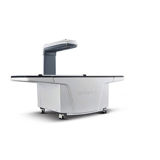
User Manuals: OsteoSys DEXXUM T DXA Bone Densitometer
Manuals and User Guides for OsteoSys DEXXUM T DXA Bone Densitometer. We have
1
OsteoSys DEXXUM T DXA Bone Densitometer manual available for free PDF download: Service Manual
OsteoSys DEXXUM T Service Manual (233 pages)
Brand:
OsteoSys
| Category:
Medical Equipment
| Size: 8 MB
Table of Contents
Revision History
2
Table of Contents
4
Cautions
4
Representations in the Service Manual
5
Indication of “CAUTION”
6
Indication of “High Voltage“
6
Indication of “WARNING”
6
Symbols
7
Service Engineer Training
8
Cautions
9
Service Program and Service Documents
10
Personal Data Protection
10
Field Replaceable Unit List and Ordering Code
11
Trouble Shooting Guide
15
System Doesn’t Start When Power Is on
19
Fuse Breaks off at Power “ON”
20
Operation/Noise
21
Equipment Doesn’t Start Initial Movement
21
Problem During Movement/Scan
22
Equipment Stops During Movement
22
Initialization When Measuring Incomplete
22
Trembling and Movement with Snapping Noise
23
No Problem with Initialization but no Movement at Default Position
23
Movement Is Slow and Unstable
23
Noise During Operation
24
Noise During Scanning
24
Problems on Parts
25
Problems with Noise and Operation of Driver
25
Replacement According to FRU Number
26
Connection /Communication
27
Check the Followings if Communication between the Equipment and PC
27
Functional Problems on Hardware Main Module
28
Laser Pointer Doesn’t Work
28
Problem with Move Key/Select Key/Led on User Control Panel
28
Problem with Buzzer
29
Problem with Shutter
29
Functional Problems on Hardware Power Module
30
Problem with Limit Switch
30
Main Board Indicator
30
Power Board Indicator
30
Trouble Shooting on Error Codes
31
A-002 Hard Disk Space Insufficiency
31
B-002 under Temperature
32
B-011 Check Detector or Main Board
33
B-012 ~ B-018 X-Ray Generator Working Error
34
B-0110 Hfg’s Temperature Getting Higher than High Temp Limit Range
38
B-0111 HFG Working Time be Exceeded (Continuous 13Min)
39
B-023 HFG Reset
39
B-031 HFG Mechanic Error
40
B-041 Request Command Time out
41
B-051 EEPROM Ma Read Failed
42
B-061 Retry (B-061)
43
C-003 Image File Could Not be Found
44
C-004 Image Format Dose Not Match
44
C-005 Could Not Find the Print Format
45
C-006 Wrong File Header
45
C-007/C-008 It Is Not Scan Area
46
C-009 Left Limit Line
46
C-010 Right Limit Line
47
C-011 File Not Found
47
C-012 Disconnected
48
C-013 this Program Does Not Support Current Resolution
49
D-001 Retype the Password
49
D-002 Patient Not Selected
50
D-004 There Is Problem in the Year of Birth
51
D-005 There Is Problem in the Month of Birth
51
D-006 There Is Problem in the Day of Birth
52
D-007 ‘Name’ Is Required
52
D-008 ‘Ethnic’ Is Required
53
D-009 ‘Height’ Is Required
53
D-010 ‘Weight’ Is Required
54
D-011 ID Marking Is Wrong. Retype the ID Mask
54
D-012 'Password Confirmation' Is Not Equal to 'New Password’
55
D-013 ‘Password’ Is Required
55
D-014 ‘Retype Password’ Is Required
56
D-018 Doctor Is Not Selected
56
D-020 Image Is Not Selected
57
D-021 Scan Site Is Not Selected
57
D-024 Release ROI Button
58
D-026 Database Server Could Not be Found
58
Daily QC Is Not Finished
59
D-030 Scan Area over (y Axis)
59
D-031 Work List Mode
60
D-040 There May be an Object on this Position
61
Daily Inspection Test
62
BMD CHECK Fail
62
Repair on Back Ground
64
Repair on Low / High Ratio / Spectrum Area
64
Repair on Spectrum
65
Moving Test
66
Trouble Shooting on Image Measured
67
Lines or Black Spots on Image
67
Patient’s Bone Image Location Is Not Identifiable
68
System Information
74
Outer Figure of DEXXUM T
74
Outer Figure of DEXXUM T (Inlet, Switch)
75
AC Input Terminal and Communication Port of DEXXUM T
75
Main Components of DEXXUM T
76
Inside of DEXXUM T
76
Inside of Carriage Mechanism of DEXXUM T
77
Locations and Names of Carriage Pulley and Coupling
78
Pully Assy; and Coupling
78
Mechanism and Frame Inside the Bed
79
Inside and Frame of the Bed
79
System Cable Connection
80
Testing each Module of Hardware
81
Removing DEXXUM T Bed and MDF
81
Dexxum T System
81
Removing MDF Using M5 Wrench
81
Combining Bed
82
Testing Main Module and Reading the Indicator
83
Removing Cover
83
Measuring Test Point Voltage and Short-Circuit Inspection
83
Measuring TEST Point Using DMM
83
Location of Main Board Test Point, 7-Segment and Ethernet Indicator
84
Voltage for each Main Module Power Test Point
85
Reading 7-Segment Indicator
85
Voltage for each Test Point
85
Reading Ethernet Indicator
86
Testing PMT Detector Main Module and Reading the Indicator
87
Removing Main Board Cover
87
Testing Power Module and Reading the Indicator
91
Measuring Test Points and Short-Circuit Inspection
91
Locations of Power Board Indicator and Voltage Test Points
92
DEXXUM T Power Board Test Points
92
DEXXUM T SMPS Connector and Indicator
92
SMPS Indicator
93
SMPS Power Input/Output
93
Voltage of each Power Board Test Point
93
Power Board Indicator (Inner Power Board
94
Testing X-Ray Generator Control Board and Reading the Indicator
99
X-Ray Generator Short-Circuit Inspection
99
X-Ray Generator Feedback Point
100
Location of X-Ray Generator Main Board and Using DMM
100
X-Ray Generator Control Board Test Points
100
X-Ray Generator Indicator and Test Points
101
CONTROL Board Test Points and Voltage
101
Reading X-Ray Generator Temperature
101
Motor Driver Indicator and Power Input Terminal
102
Motor Driver Setting Values (this Chart Is Only Available for KR55MC)
102
Checking User Control Switches
103
Measuring User Operated Switch Signal
103
Test Points of User Control Panel
104
Listed in the Order of Test Points Located in the Right of OCON1
104
Measuring Laser Pointer Voltage
105
Removing Carriage Bottom Cover
105
Removing Connector
105
Top Cover Fixing Points
106
Laser Pointer Control Connector
106
Testing Limit Switch and Shutter Board Limit Switch
107
Limit Switch
107
Checking Limit Switch
107
Testing Detector Noise
108
Main Board’ Shutter IC
109
Measuring Shutter Motor Signal
109
DVM Measuring Point
110
Screenshot of the Test Program
111
Connecting Test Program
112
Setting PC LAN CARD Network IP
112
IP Address Setting
112
Value Setting in Test Program
113
EEPROM Read Window
114
Moving Device and Testing with Test Program.
114
Moving Device
114
Main Menu
115
Get Temperature
115
Indicating Temperature
115
Description of Get Count Menu
116
Get Count Window
116
Way to Obtain Get Spectrum and Checking Errors of Spectrum
117
Spectrum Menu on the Main Tab
117
Get Spectrum Window
118
Description of Get Spectrum Menu
118
Scan Menu on the Main Tab
120
Scan Window
120
Table of Setting Functions on Scan Option Window
121
Gain Control Window
123
Gain Control Method and Checking Errors on Main Control B/D
123
“G” Menu on the Main Tab
123
How to Disassemble the Cover
125
Removing Front Cover (FRU NO: FRU009-061)
125
Removing Back Cover (FRU NO:FRU009-066)
126
Connector on Back Cover
126
Back Cover Removed
127
Removing Carriage Top & Bottom Cover
127
Removing Wrench Bolts Fixed to Bottom Cover
127
Column Front/Rear Wrench Bolt Locations
129
Removing Bolts Connecting Column Front & Rear
129
Removing Column Front Cover & Column Rear Cover
129
Left Side Cover Right Loosening/Tightening Wrench Bolt
130
Removing Left Side Cover & Right Side Cover
130
Left Side & Right Side Cover
130
Short Bed Wing Cover and Panel
131
Replacing Bed Wing
131
Short Bed Wing
131
Middle Bed Wing
132
Long Bed Wing
132
Replacing MDF and Urethane Bed
133
Replacing MDF
133
Before Removing MDF after Removing Bed
133
After MDF Removed
134
DEXXUM T Center Bed
134
Checking Flatness of Urethane Bed
135
DEXXUM T Center Bed Assembly Location
135
Combining Wing Bed
136
Removing Bed Cover and Urethane Bed
136
Cover with Stickers
136
Urethane Bed and Bed Cover Combined
136
Testing Parts
137
Testing Film Curtain
137
H2EA-006A Connector
137
Fixing Points of Back Cover
137
Carriage Timing Belt
139
Testing Timing Belt
139
Timing Belt of Carriage Detector
139
Bed Timing Belt
140
Adjusting Timing Belt Tension and Tension
141
Torque Wrench for Tension Adjustment
141
Adjusting Y-Axis Timing Belt Tension
141
Adjusting Bed Timing Belt
141
Adjusting X-Ray Generator Timing Belt
142
Fixing Wrench Bolts of Front Cover
142
Jig for Adjusting Timing Belt of X-Ray Generator
142
Adjusting Detector Timing Belt
143
Jig for Adjusting Tension of Detector Timing Belt
143
Testing Motor Key/Coupling
144
Motor Key Location and Combining Hole of Pulley and Motor Key
144
Coupling Location
144
Testing Pulley/Bearing
146
Initialization and Movement Control for Testing the Equipment
147
Motor Movement Control
147
Replacing Module and Parts and Adjusting Location
148
Replacing and Testing Main Module, PMC Assy
148
Is X-Ray Generator Operating Normally?
149
Replace Power Module of Carriage
149
Is Power Normal When Reading the Indicator?
149
Replacing Power Module (FRU No: FRU009-28)
149
Replacing X-Ray Generator (FRU No: FRU009-29)
150
Removing Shutter Block on X-Ray Generator
150
Wrench Bolt Fixing Location
150
X-Ray Generator Installation Direction
151
Combining Square Nut and Wrench Bolt
151
Replacing Detector (CZT,PMT)
153
Removing Bottom Cover Fixing Wrench Bolts
153
Removing Cable Duct and Connector Connection
154
Detector Fixing Points
155
Replacing Motor Driver
156
7-5. Replacing Motor Driver (FRU NO: FRU009-33A)
156
Replacing Shutter Module
157
Replacing Limit Switch (FRU NO: FRU009-038)
158
Replacing and Adjusting Limit Block
159
Adjusting and Fixing X-Axis Limit Block Location
159
Y-Axis Limit Block Location
160
Proper Height of Limit Block
160
Replacing Timing Belt
161
Y-Axis Timing Belt (FRU NO: FRU009-71)
161
Replacing Y-Axis Timing Belt
161
Y-Axis Belt Pulley Brkt’ Fixing Part
161
Removing the Connector
162
Replacing Detector Timing Belt (FRU NO: FRU009-072)
162
Detector Timing Belt
163
Combined Timing Belt
163
Replacing X-Ray Generator Timing Belt (FRU NO: FRU009-073)
164
Wrench Bolt Location
164
Disassembling Timing Belt and X-Ray Generator Plate
165
Disassembling Timing Belt and X-Ray Generator Plate Assy’
165
General Alignment
166
Timing Belt and Pulley Assy;
166
Inlet and Ethernet Connector of the Back of the Cover
167
Removing Back Cover
167
Replacing Motor
167
After Back Cover Removed
168
Adjusting Coupling
168
Replacing Y-Axis Motor
170
Locations of Y-Axis Pulley and Motor Assy’ Fixing
170
Removing Motor Assy
170
Removing Brkt’ and Motor
171
Combining Location of Motor Assy’
171
Replacing Bearing and Pulley (FRU NO: FRU009-44)
172
Idle Pulley and Roller Idle FLAT
172
Removing Idle Pulley and Roller Idle FLAT
172
Idle Pulley Assy’’ on X-Ray Generator Side
173
Replacing Idle Pulley Assy’ (FRU NO: FRU009-40)
173
Idle Pulley Assy’ on Detector Side
173
Replacing Shaft Pulley (FRU NO: FRU009-42)
174
Location of Wrench Bolts of Shaft Pulley
174
Replacing Shaft Pulley
174
Replacing Curtain Film
175
Connector on the Back of the Cover
175
DEXXUM T Film Fixing Brkt’
176
Fixing Film
176
Fixing Location of DEXXUM T Curtain Film
177
Adjusting Film Tension and Fixing Brkt’
178
Carriage Film Replacement and Plastic Fixing Cap
179
Replacing Carriage Bottom Cover(Detector Cover) Film
179
Replacing User Control Switch (FRU NO: FRU009-036)
180
Removing User Operated Switch Connector
180
Removing User Operated Switch
181
Connecting User Operated Switch and Cable
181
User Operated Switch
182
Replacing Emergency Switch (FRU NO: FRU009-043)
183
Removing Emergency Switch Connector
183
Fixing Metal Location for Emergency Switch
184
Removing Fixing Switch with Tweezers
184
Fixing Direction for Emergency Switch
184
Replacing Laser Pointer and Alignment of Laser Pointer
185
Replacing Laser Pointer
186
Removing Laser Pointer Connector
186
Aligning Laser Pointer
187
Laser Pointer Alignment
187
Way to Use the Laser Pointer Alignment JIG
188
Laser Pointer JIG
188
Fixing JIG
188
Position of Collimator Hole
188
Standard Horizontal Line
189
Way to Adjust Vertical, Horizontal Line of Laser Pointer
189
Hole on Cable Duct Guide
189
Replacing Curtain Film Roller and Roller Shaft
190
Locations of Curtain Film Roller and Shaft
190
Removing Snap Ring
190
Top of Curtain Film Roller
191
Bottom of Curtain Film Roller
191
Location of Wrench Bolts for Fixing Shaft
191
Roller Shafts and Back Cover Supporter
192
Location of each Shaft
192
Replacing Fuse
194
Location of the Fuses and Removing the Fuses
194
Removing DEXXUM T Cover and Main Switch
195
Removing Main Switch and Cable
195
Replacing Main Switch (FRU NO: FRU009-023)
195
Replacing Inlet/ Inlet Board
196
Removing/Replacing Inlet from System
196
Removing/Replacing Inlet Board from System
196
Replacing X-Ray Generator Fan
197
Removing X-Ray Generator Cover
197
Fan Connector of X-Ray Generator Main Board
197
Removing Fan
198
Software
199
UI Installation
199
Start Installation
200
Database Installation
201
Recovering or Removing UI
206
Recovery
206
Checking Window During Removal
207
Advanced UI Setup
208
Description of Advanced UI Setup Items
209
Parameter
210
Image Size (Normal)
210
X Scan Area
210
Default Position
210
Calibration Position
211
Standard BMD (QC Phantom)
211
Daily QC Condition
211
QC Path /Standard Fitting/Thin Fitting
211
Command Check
212
Firmware Ver 1.9 or above Required
212
Forearm Scan
212
Forearm Daily Test
212
UI Patient Data Backup and Recovery
213
UI Patient Data Backup Method
213
Generate Files
218
Registry Recovery
218
PACS Connection Method
221
PACS Requirements
221
PACS Link
221
Work List Link
226
UI Setup for Work List
226
Work-List Input
227
Patient Loading on Work-List
228
Search Patients
229
Enter Information on the First Patient
229
Checking Password
229
Execute Password Finder
229
Check the Firmware Version of DEXXUM T Main Module
230
DEXXUM T Diagnostic Function Check
231
Advertisement
Advertisement
Related Products
OsteoSys SONOST 3000
OsteoSys SONOST-2000
OsteoSys Categories
Medical Equipment
Measuring Instruments
More OsteoSys Manuals
Login
Sign In
OR
Sign in with Facebook
Sign in with Google
Upload manual
Upload from disk
Upload from URL