Sign In
Upload
Manuals
Brands
Oshkosh Corporation Manuals
Boom Lifts
JLG E400A Narrow
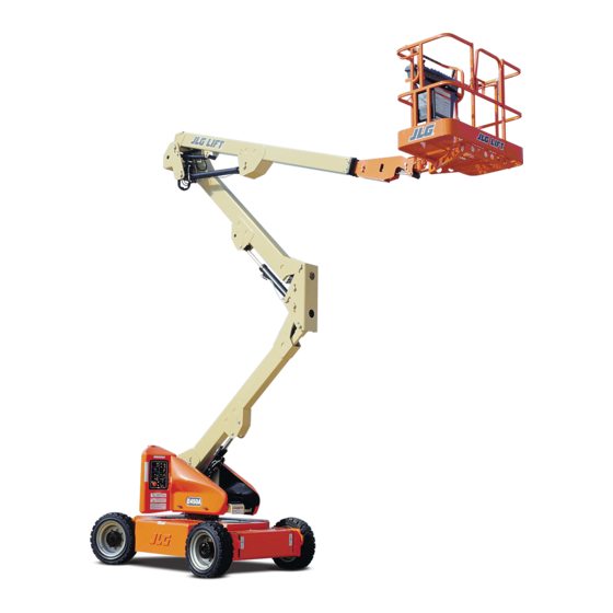
Oshkosh Corporation JLG E400A Narrow Manuals
Manuals and User Guides for Oshkosh Corporation JLG E400A Narrow. We have
4
Oshkosh Corporation JLG E400A Narrow manuals available for free PDF download: Service And Maintenance Manual, Operation And Safety Manual
Oshkosh Corporation JLG E400A Narrow Service And Maintenance Manual (261 pages)
Brand:
Oshkosh Corporation
| Category:
Boom Lifts
| Size: 20 MB
Table of Contents
Bhydraulic System Safety
3
Maintenance
3
Table of Contents
5
Section 1 - Specifications
16
Operating Specifications
16
Capacities
16
Battery Charger
16
Drive System
16
Hydraulic Pump/Electric Motor Assembly
16
Generator
16
Tires
16
Dimensional Data
17
Function Speeds
17
Machine Orientation When Doing Function Tests
18
Torque Specifications
18
Cylinder Specifications
19
Major Component Weights
19
Critical Stability Weights
20
Pressure Settings
20
Serial Number Locations
21
Lubrication
21
Lubrication Specifications
21
Operator Maintenance & Lubrication
23
Section 2 - General
34
Machine Preparation, Inspection, and Maintenance
34
General
34
Preparation, Inspection, and Maintenance
34
Pre-Start Inspection
34
Pre-Delivery Inspection and Frequent Inspection
34
Annual Machine Inspection
34
Preventive Maintenance
34
Service and Guidelines
35
General
35
Safety and Workmanship
35
Cleanliness
35
Components Removal and Installation
35
Component Disassembly and Reassembly
36
Pressure-Fit Parts
36
Bearings
36
Gaskets
36
Bolt Usage and Torque Application
36
Hydraulic Lines and Electrical Wiring
36
Hydraulic System
36
Lubrication
36
Battery
36
Lubrication and Servicing
36
Hydraulic Oil
37
Changing Hydraulic Oil
37
Lubrication Specifications
37
Cylinder Drift Test
37
Platform Drift
37
Cylinder Drift
37
Pins and Composite Bearing Repair Guidelines
38
Welding on JLG Equipment
38
Do the Following When Welding on JLG Equipment
38
Do NOT Do the Following When Welding on JLG Equipment
38
Engine Operating Temperature Specifications - Kubota
42
Section 3 - Chassis & Turntable
44
Tires & Wheels
44
Tire Inflation
44
Tire Damage
44
Tire Replacement
44
Wheel Replacement
44
Wheel Installation
44
Spindle
45
Setting Wheel Bearing End Play
45
Specifications
45
Checking
45
Greasing Requirements
45
Drive Hub (Part No. 2780236)
47
Dissembling
47
Disassembly
48
Disassembly of the First Stage Planetary Assembly (7)
48
Disassembly of Second Stage Planet Gears (1)
48
Assembly of First Stage Planetary Assembly (7)
48
Assembly of End Cover Unit (8)
48
Final Assembly
49
Initial Start-Up and after Repairs
49
Maintenance
49
Oil Change Interval-Gear Drive
49
Setting of Tapered Roller Bearings
49
Securing of the Shaft Nut
49
Drive Hub- Cutaway
49
Drive Brake - Mico
51
Disassembly
51
Assembly
51
Bleeding
51
Drive Brake
51
Speed Sensor Adjustment
54
Adjustment Procedure
54
Speed Sensor Orientation
55
Speed Sensor Installation Verification
59
Verification W/ Analyzer Procedure
59
Positrac/Tilt Module
62
Swing Motor - S/N 0300135649 to Present
64
Swing Motor - Cutaway
64
Swing Motor - Exploded View
66
Preparation before Disassembly
67
Disassembly and Inspection
67
Assembly
73
One Piece Stator Construction
80
Two Piece Stator Construction
81
Final Checks
81
Swing Bearing
82
Turntable Bearing Mounting Bolt Condition Check
82
Swing Bearing Feeler Gauge Check
82
Wear Tolerance
83
Swing Bearing Tolerance Boom Placement
83
Replacement of Swing Bearing
84
Swing Bearing Tolerance Measuring Point
84
Swing Bearing Torquing Sequence
85
Swing Bearing Torque Value
86
Checking Worm Gear End Play
86
Adjusting End Play
86
Battery Maintenance and Charging
88
Battery Maintenance, Quarterly
88
Charging Sequence of Remote LED Card
88
Remote LED Card
88
Battery Cable Connections
89
Battery Charging (on Board Charger)
90
Optional on Board Generator
90
Batteries and Battery Charger (Prior to S/N 0300059350)
90
On Board Generator
90
Battery Charger (S/N 0300059350 to Present)
92
Battery Charger ((S/N 0300059350 to Present)
92
Operating Instructions
92
Maintenance Instructions
92
Battery Charger Fault Codes
92
Excessive Battery Watering Requirements or Strong Sulphur (Rotten Egg) Smell
95
Checking/Changing the Battery Charger Algorithm
96
Generator (Prior to S/N 88539)
97
Alternator
97
Dynamo and Dynamo Voltage Regulator
97
Dynamo Output Fuse
97
Control Fuse
97
Start Battery
97
Engine Starter
97
Start Control Relay
97
Fuel Control Relay
97
Fuel Solenoid
97
To Connect the JLG Control System Analyzer to the Generator
100
Alarms and Fault Flash Codes
100
Output Current and Voltage Settings
102
Priming the Fuel Line
103
Generator (S/N 88539 to Present)
104
Engine
104
Alternator
104
Dynamo and Dynamo Voltage Regulator
104
Dynamo Output Fuse
104
Control Fuse
104
Start Battery
106
Engine Starter
106
Start Control Relay
106
Fuel Control Relay
107
Glow Plug Control Relay
107
Glow Plug
107
Fuel Pump
108
Fuel Solenoid
108
Engine Low Oil Pressure Switch
108
Engine Oil Temperature Sensor
108
Alternator Output Current Sensor
109
Engine Speed Sensor
109
RBS Engine/Generator Controller
109
Warnings and Safety Precautions
110
System Controls
110
System Status and Performance Monitoring
110
System Settings
110
RBS Start
111
RBS Shutdown
111
RBS Alarms and Flash Codes
112
Resetting the RBS Controller
112
Maintenance Schedule
112
Troubleshooting
113
APU Engine Start Battery Boosting
114
Supplementary Fuse for Apu
115
Tools and Material
115
Procedure
115
Section 4 - Boom & Platform
118
Boom Maintenance
118
Removal
118
Disassembly
118
Inspection
119
Assembly
119
Installation
120
Upper (Main) Boom Lift Cylinder
121
Removal
121
Installation
121
MID Boom Lift Cylinder
121
MID Boom Lift Cylinder Removal
121
Installation
122
Lower Boom Lift Cylinder
122
Removal
122
Lower Boom Lift Cylinder Removal
122
Upper Boom Telescope Cylinder
123
Removal
123
Installation
123
MID and Lower Lift Cylinder Bleeding Procedure
124
Wear Pads
124
Boom Synchronizing Procedure
125
Articulating Jib Boom
125
Removal
125
Disassembly
125
Inspection
125
Assembly
127
Footswitch Adjustment
127
Boom Limit Switches
127
Helac Rotary Actuator
129
Theory of Operation
129
Tools Required for Assembly/Disassembly
132
Disassembly
132
Inspection
136
Assembly
136
Installing Counterbalance Valve
140
Testing the Actuator
140
Installation and Bleeding
142
Troubleshooting
143
Powertrack Maintenance
144
Removing a Link
144
Installing a New Link
147
Replacing Fixed End Brackets
152
Replacing Moving End Brackets
154
Section 5 - Hydraulics
157
Lubricating O-Rings in the Hydraulic System
157
Cup and Brush
157
Dip Method
158
Spray Method
158
Brush-On Method
158
Cylinders - Theory of Operation
159
Double Acting Cylinder
159
Cylinder Checking Procedures
159
Cylinder Without Counterbalance Valves
159
Cylinders with Single Counterbalance Valve
159
Cylinders with Dual Counterbalance Valve
170
Cylinder Repair
170
Disassembly
170
Cleaning and Inspection
171
Assembly
172
Pressure Setting Procedures
176
Main Relief
176
Upper Lift down Relief
176
Lower Lift down Relief
176
Telescope Relief
176
Platform Level up Relief
176
Platform Level down Relief
177
Steer Relief
177
Jib Lift (up and Down) Relief
177
Jib Swing Relief
177
Releveling Valve Relief
177
Section 6 - Jlg Control System
184
JLG Control System Analyzer Kit Instructions
184
Introduction
184
To Connect the JLG Control System Analyzer
185
Using the Analyzer
186
Changing the Access Level of the Hand Held Analyzer
187
Adjusting Parameters Using the Hand Held Analyzer
188
Machine Setup
188
Machine Personality Settings
189
Machine Configuration Programming Information
193
Level Vehicle Description
194
Help Descriptions and Fault Flash Codes
194
Analyzer Diagnostics Menu Structure
204
System Self Test
205
Section 7 - Basic Troubleshooting, Electrical Information, & Schematics
218
General
218
Troubleshooting
218
Multimeter Basics
236
Grounding
236
Backprobing
236
Min/Max
236
Polarity
236
Scale
236
Voltage Measurement
236
Resistance Measurement
237
Continuity Measurement
237
Current Measurement
238
Checking Switches
238
Basic Check
238
Limit Switches
238
Automatic Switches
239
Switch Wiring - Low Side, High Side
239
Applying Silicone Dielectric Compound to Electrical Connections
239
AMP Connector
240
Applying Silicone Dielectric Compound to AMP Connectors
240
Assembly
240
Disassembly
242
Wedge Lock
242
Service - Voltage Reading
242
Deutsch Connectors
244
DT/DTP Series Assembly
244
DT/DTP Series Disassembly
244
HD30/HDP20 Series Assembly
245
HD30/HDP20 Series Disassembly
245
Advertisement
Oshkosh Corporation JLG E400A Narrow Operation And Safety Manual (103 pages)
Brand:
Oshkosh Corporation
| Category:
Boom Lifts
| Size: 19 MB
Table of Contents
Table of Contents
7
Section 1 - Safety Precautions
12
General
12
Pre-Operation
12
Operator Training and Knowledge
12
Workplace Inspection
13
Machine Inspection
14
Operation
14
General
14
Trip and Fall Hazards
15
Electrocution Hazards
16
Minimum Approach Distances (M.A.D.)
17
Tipping Hazards
18
Beaufort Scale (for Reference Only)
20
Crushing and Collision Hazards
21
Towing, Lifting, and Hauling
22
Maintenance
22
Maintenance Hazards
22
Battery Hazards
23
Section 2 - User Responsibilities, Machine Preparation, and Inspection
24
2.1 Personnel Training
24
Operator Training
24
Training Supervision
24
Operator Responsibility
25
Machine Familiarization
25
2.2 Preparation, Inspection, and Maintenance
25
Inspection and Maintenance Table
26
Basic Nomenclature
27
Pre-Start Inspection
28
Walk-Around Inspection
30
Function Check
33
Skyguard Function Test
34
Section 3 - Machine Controls and Indicators
35
General
35
Controls and Indicators
35
Ground Control Console
36
Ground Control Console
37
Platform Console
41
Platform Control Console
42
Platform Control Indicator Panel
46
Platform Control Indicator Panel
47
Section 4 - Machine Operation
50
Description
50
Boom Operating Characteristics and Limitations
50
Capacities
50
Platform Load Sensing System (LSS)
51
Stability
51
Position of Least Backward Stability
51
Position of Least Forward Stability
52
Motor Operation
54
Power/Emergency Stop
54
Platform/Ground Select Switch
54
Motor Activation
54
Traveling (Driving)
55
Traveling Forward and Reverse
56
Grade and Side Slopes
57
Traveling on a Grade
58
Steering
58
Platform
58
Loading from Ground Level
58
Loading from Positions above Ground Level
58
Platform Level Adjustment
59
Platform Rotation
59
Jib Swing
59
Boom
59
Swinging the Boom
60
Raising and Lowering the Lower and MID Boom
60
Raising and Lowering the Upper Boom
60
Generator
61
Automatic Operating Mode
61
Battery Only Operating Mode
61
Manual (Charge) Operating Mode
62
Inverter
62
4.10 Machine Function Speeds
63
Machine Safety System Override (Msso)
63
(Ce Only)
63
4.12 Skyguard Operation
64
Skyguard
64
Skyguard - Skyline
64
Skyguard - Skyeye
65
Skyguard Function Table
65
4.13 Boom Synchronizing Procedure
66
4.14 Shut down and Park
66
4.15 Machine Lifting and Tie down
67
Lifting
67
Tie down
67
Lifting Chart
68
E400An/E400Ajpn Decal Legend
75
Section 5 - Emergency Procedures
78
General
78
Incident Notification
78
Emergency Operation
78
Operator Unable to Control Machine
78
Platform or Boom Caught Overhead
79
Emergency Towing Procedures
79
Manual Descent System
80
Manual Swing Override
80
Machine Safety System Override (Msso)
80
(Ce Only)
80
Section 6 - Accessories
81
Available Accessories
81
Pipe Racks
82
Safety Precautions
82
Preparation and Inspection
83
Operation
83
Section 7 - General Specifications & Operator Maintenance
84
Introduction
84
Operating Specifications
84
Capacities
85
Tires
86
Dimensional Data
86
Tire Specifications
86
Torque Specifications
87
Hydraulic Oil
87
Torque Requirements
87
Mobil DTE 10 Excel 15 Specs
88
Mobil EAL Envirosyn H 32 Specs
88
Critical Stability Weights
89
Mobil EAL Envirosyn SHC 32 Specs
89
Serial Number Locations
90
Maintenance and Lubrication
92
Lubrication Specifications
92
Battery Maintenance and Charging
98
Battery Maintenance, Quarterly
98
Optional on Board Generator
98
Battery Charging (on Board Charger)
99
Tires & Wheels
99
Tire Damage
99
Tire Replacement
100
Wheel Replacement
100
Wheel Installation
100
Supplemental Information
101
Wheel Torque Chart
101
Oshkosh Corporation JLG E400A Narrow Operation And Safety Manual (118 pages)
Brand:
Oshkosh Corporation
| Category:
Boom Lifts
| Size: 2 MB
Table of Contents
Table of Contents
7
Section 1. Safety Precautions
11
General
11
Pre-Operation
11
Operator Training and Knowledge
11
Workplace Inspection
12
Machine Inspection
12
Operation
13
General
13
Trip and Fall Hazards
13
Electrocution Hazards
14
Minimum Approach Distances (M.A.D.)
15
Tipping Hazards
16
Crushing and Collision Hazards
17
Towing, Lifting, and Hauling
18
Additional Hazards / Safety
19
Section 2 - User Responsibilities, Machine Preparation, and Inspection
21
2.1 Personnel Training
21
Operator Training
21
Training Supervision
21
Operator Responsibility
21
Preparation, Inspection, and Maintenance
22
Pre-Start Inspection
24
Function Check
25
Basic Nomenclature
27
General
31
Section 3 - Machine Controls and Indicators
31
Controls and Indicators
31
Ground Control Station
31
Ground Control Station
33
Ground Control Station W/ Function Enable
34
Platform Station
36
Platform Control Console
37
Platform Control Console W/ Drive Orientation
38
Platform Control Indicator Panel
42
Platform Control Indicator Panel
43
Platform Control Indicator Panel W/Drive Orientation
43
Section 4 - Machine Operation
47
Description
47
Operating Characteristics and Limitations
47
Capacities
47
Stability
48
Motor Operation
48
Power/Emergency Stop
48
Position of Least Forward Stability
49
Platform/Ground Select Switch
51
Motor Activation
51
Traveling (Driving)
51
Traveling Forward and Reverse
52
Steering
52
Platform
53
Loading from Ground Level
53
Loading from Positions above Ground Level
53
Platform Level Adjustment
55
Platform Rotation
55
Jib Swing
55
Boom
56
Swinging the Boom
56
Raising and Lowering the Lower and MID Boom
56
Raising and Lowering the Upper Boom
57
Generator
57
Automatic Operating Mode
57
Battery Only Operating Mode
57
Manual (Charge) Operating Mode
57
Inverter
58
4.10 Machine Function Speeds
58
4.11 Shut down and Park
58
4.12 Boom Synchronizing Procedure
59
4.13 Machine Lifting and Tie down
59
Lifting
59
Tie down
59
Lifting Chart
60
E400A/E400AJP Decal Legend
66
E400A/E400AJP Decal Legend - S/N 0300142589 to Present
72
M400A/M400AJ Decal Legend
78
M400A/M400AJ Decal Legend - S/N 0300142589 to Present
83
Section 5 - Emergency Procedures
89
General
89
Incident Notification
89
Emergency Operation
89
Operator Unable to Control Machine
89
Platform or Boom Caught Overhead
90
Emergency Towing Procedures
90
Manual Descent System
90
Manual Swing Override
91
Section 6 - General Specifications & Operator Maintenance
93
Introduction
93
Operating Specifications
93
Operating Specifications - Prior to
93
Operating Specifications - S/N 0300142589
94
Capacities
96
Tires
96
Dimensional Data
97
Torque Specifications
97
Hydraulic Oil
98
Critical Stability Weights
99
Serial Number Locations
100
Operator Maintenance
102
Operator Maintenance & Lubrication Diagram
102
Battery Maintenance and Charging
107
Battery Maintenance, Quarterly
107
Battery Charging (on Board Charger)
108
Optional on Board Generator
108
Tire Damage
109
Tire Inflation
109
Tire Replacement
109
Tires & Wheels
109
Wheel Installation
110
Wheel Replacement
110
Supplemental Information
111
Wheel Torque Chart
111
Section 7. Inspection and Repair Log
113
Inspection and Repair Log
114
Advertisement
Oshkosh Corporation JLG E400A Narrow Operation And Safety Manual (118 pages)
Brand:
Oshkosh Corporation
| Category:
Boom Lifts
| Size: 1 MB
Table of Contents
Table of Contents
7
Section 1 - Safety Precautions
15
General
15
Pre-Operation
15
Operator Training and Knowledge
15
Workplace Inspection
16
Machine Inspection
17
Operation
17
General
17
Trip and Fall Hazards
18
Electrocution Hazards
19
Tipping Hazards
21
Crushing and Collision Hazards
24
Towing, Lifting, and Hauling
25
Maintenance
25
Maintenance Hazards
25
Battery Hazards
27
Section 2 - User Responsibilities, Machine Preparation, and Inspection
29
2.1 Personnel Training
29
Operator Training
29
Training Supervision
29
Operator Responsibility
29
Preparation, Inspection, and Maintenance
30
Pre-Start Inspection
32
Function Check
33
Skyguard Function Test
35
General
38
Section 3 - Machine Controls and Indicators
41
General
41
Controls and Indicators
41
Ground Control Station
42
Platform Station
47
Platform Control Indicator Panel
54
Section 4 - Machine Operation
59
Description
59
Operating Characteristics and Limitations
59
Capacities
59
Stability
60
Motor Operation
60
Power/Emergency Stop
60
Platform/Ground Select Switch
63
Motor Activation
63
Traveling (Driving)
63
Traveling Forward and Reverse
64
Steering
66
Platform
66
Loading from Ground Level
66
Loading from Positions above Ground Level
66
Platform Level Adjustment
67
Platform Rotation
67
Jib Swing
67
Boom
68
Swinging the Boom
68
Raising and Lowering the Lower and MID Boom
68
Raising and Lowering the Upper Boom
68
Generator
69
Automatic Operating Mode
69
Battery Only Operating Mode
69
Manual (Charge) Operating Mode
70
Inverter
70
4.10 Machine Function Speeds
70
Machine Safety System Override (Msso)
71
4.12 Skyguard Operation
71
4.13 Boom Synchronizing Procedure
72
4.14 Shut down and Park
72
4.15 Machine Lifting and Tie down
73
Lifting
73
Tie down
73
Section 5 - Emergency Procedures
89
General
89
Incident Notification
89
Emergency Operation
89
Operator Unable to Control Machine
89
Platform or Boom Caught Overhead
90
Emergency Towing Procedures
90
Manual Descent System
90
Manual Swing Override
90
Machine Safety System Override (Msso)
91
Section 6 - General Specifications & Operator Maintenance
93
Introduction
93
Operating Specifications
93
Capacities
95
Tires
95
Dimensional Data
96
Torque Specifications
96
Hydraulic Oil
97
Critical Stability Weights
98
Serial Number Locations
99
Maintenance and Lubrication
102
Battery Maintenance and Charging
108
Battery Maintenance, Quarterly
108
Optional on Board Generator
109
Battery Charging (on Board Charger)
109
Tires & Wheels
110
Tire Inflation
110
Tire Damage
110
Tire Replacement
110
Wheel Replacement
111
Wheel Installation
111
Supplemental Information
112
Section 7 - Inspection and Repair Log
113
Advertisement
Related Products
Oshkosh Corporation JLG E300A
Oshkosh Corporation JLG E300AJ
Oshkosh Corporation JLG E600
Oshkosh Corporation JLG E600J
Oshkosh Corporation JLG E600JP
Oshkosh Corporation JLG E450A
Oshkosh Corporation JLG E450AJ
Oshkosh Corporation JLG E400AN
Oshkosh Corporation JLG M600J
Oshkosh Corporation JLG 800S
Oshkosh Corporation Categories
Boom Lifts
Lifting Systems
Scissor Lifts
Industrial Equipment
Air Compressor
More Oshkosh Corporation Manuals
Login
Sign In
OR
Sign in with Facebook
Sign in with Google
Upload manual
Upload from disk
Upload from URL