Sign In
Upload
Manuals
Brands
Orbit Manuals
Marine Radar
OCEANTRX4-500
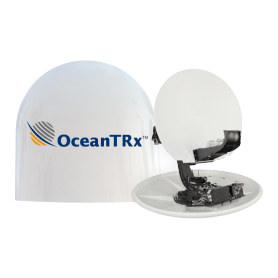
Orbit OCEANTRX4-500 Manuals
Manuals and User Guides for Orbit OCEANTRX4-500. We have
1
Orbit OCEANTRX4-500 manual available for free PDF download: Installation And Operation Manual
Orbit OCEANTRX4-500 Installation And Operation Manual (197 pages)
1.15m (45”) Linear Ku-Band Maritime Stabilized VSAT System
Brand:
Orbit
| Category:
Marine Radar
| Size: 7 MB
Table of Contents
About this Manual
2
Table of Contents
7
1 Introduction
11
About Orbit
12
About Oceantrx TM 4-500 Ka Band Inherent Support
13
Oceantrx™4 Key Features and Advantages
15
System Architecture for Standard Topology
17
Dual System Topologies
18
Ku-Band BUC Configurations
19
Control and Monitoring
20
2 System Description
21
System RF Layout
22
Above Deck Equipment (ADE) - Antenna Unit
23
Central Control Unit (CCU)
24
Dual System Selector (DSS)
26
3 Pre-Installation Requirements
29
System Physical Specifications
30
Overview of the Pre-Installation Requirements
30
Location for ADE
32
Surface Stability
32
Location Criteria
32
Radome Support (Mast) Requirements
33
Support Structure Minimum Requirements
34
Example of Mast Design
35
Mounting Surface Layout
36
Crane and Harness Specifications
38
Main Power Cabling and UPS Guidelines
39
Power Requirements
39
Cabling Guidelines
39
Verify Tx/Rx Path Gain Budgets
39
Oceantrx4-500 Single System Configuration
43
Oceantrx4-500 Dual System Configuration
47
Pre-Installation Checklist
53
4 Unpacking and Mounting
55
Unpacking the System
56
Crate Dimensions
56
Crate Inspection and Unpacking
57
Mounting ADE
58
Securing and Lifting Antenna System
58
Mounting and Securing Onto the Support Structure (E.g. Mast)
60
5 Installation Procedure
61
Required Tools
62
ADE Physical Preparations and Connections
62
Opening the Hatch
63
Unlocking the Pedestal Axes
63
ADE to BDE LMR Coaxial RF Cable Connection
64
Power Connections and Power on
65
BDE Installation Procedure
66
Rack Installation Criteria
66
CCU Installation Procedure
67
DSS Installation Procedure
69
6 Navigating the Mtsvlink
73
Opening a Session to the CCU
74
Main Screens
76
Startup Screen
77
Basic Screen
78
Operation Screen
80
Saving Configuration Changes
82
Shortcuts
83
Configuring the Display
84
7 Setup Procedure
85
Overview of the Commissioning Procedure
86
Compass Input Configuration
86
Selecting Compass Type
86
Set Compass Communication Parameters
87
Setting Ship's Heading Manually
89
Selecting a Satellite
89
Loading a Satellite List File
90
Manually Defining a Satellite
91
Defining Channels (Tracking Signals)
92
Selecting the Desired Satellite and Channels
94
Perform Compass Offset
95
Setup Blockage Zone
99
Acquire Satellite and Verify AGC
102
Openamip Connection - Optional for Idirect Modems
103
CPI and 1Dbcp Compression Point Test
104
Configure Modem and Verify Rx Lock
105
Satellite Validation
105
Fine Adjustment (1Dbc)
106
Submitting the Commissioning Checklist
107
8 System Operation
109
System Operation Modes
110
Operating Modes Menu Options
110
Acquire Mode
111
Acquire Satellite Preset Mode
111
Step-Track Mode
112
Peak Mode
112
Point to Satellite Mode
112
Satellite Preset Mode
113
Search Mode
113
Stand-By Mode
114
8.1.10 Manual Mode
114
8.1.11 Stow Mode
115
8.1.12 Test Trajectory Mode
116
8.1.13 Program Route Mode
117
8.1.14 Acquire Program Track Mode
117
Satellite Database Management
117
Configuring the Satellite Database
117
Filtering the View of Available Satellite Definitions
121
Managing the Satellite Database
121
Manual Input to the System
124
Setting the AGC Threshold
124
Setting the Ship's Heading
125
Setting the GPS Position
126
Rebooting the ACU
127
Configuring Host Hardware Interfaces
127
Host Hardware Interface Dialog
127
Compass Configuration
128
Viewing Additional Modem Parameters
130
Configuring IRD Signal Lock
131
Configuring the GPS Output Hardware Interface
132
Configuring the Cease Tx Function
133
Tx Chain Windows
134
Configuring the Restart Mode
136
Configuring AGC Threshold
137
Configuring the NBR
138
System Constellation and Communication Parameters
139
9 Monitoring and Analysis Tools
141
Spectrum Analyzer Tool
142
Navigating the Spectrum Analyzer Tool
143
Acquisition Criteria
145
Configuring the Display
146
Running a Measurement
147
Graphics Data Logger
150
Using the Graphic Data Logger
150
Configuring the Graphic Data Logger
150
Logging Data with the Graphic Data Logger
151
Analyzing and Saving Logger Data
152
Calibrating and Activating Noise Floor Correction
154
Calibrating the Noise Floor
154
Typical Noise Floor Curves
156
Activating Noise Floor Correction
158
Monitoring System Voltage and Temperature Test Points
159
Monitoring the Mtsvlink Work Session
159
System Messages Log
160
Downloading the Status Dump File
161
Viewing Software Version Details
162
Appendix A: Technical Specifications
163
Appendix B: MIB for the Antenna Control Unit
167
Appendix C. Status Messages
173
Messages (Informative
173
Warning Messages
174
Error Messages
176
Appendix D: BDE Equipment Pinout
179
Modem M&C Connector Pin-Out
179
SYNCHRO & SBS Compass Connector Pin-Out
179
NMEA Compass Connector Pin-Out
181
Appendix E: Preparing the ADE-BDE Cable
185
Appendix F: Pre-Installation Checklist
186
Mechanical Stability
186
Maintenance Access
186
Line of Sight
187
Other Considerations
187
Mounting Surface
187
Appendix G: Installation Checklist
189
Please Check the State of the G-Shock Detectors and Mark Their Color
189
Crate Visual Inspection
190
Appendix H: Commissioning Checklist
191
Mechanical Stability
191
Maintenance Access
191
Other Considerations
192
Mounting Surface
192
Advertisement
Advertisement
Related Products
Orbit OceanTRx7
Orbit OceanTRx
Orbit OC 7520
Orbit OSP0043
Orbit OBE8729
Orbit OBK8612
Orbit OBB5101A
Orbit ORBITF3400
Orbit OSP125
Orbit OBB025M
Orbit Categories
Timer
Irrigation System
Exercise Bike
Fitness Equipment
Lawn and Garden Equipment
More Orbit Manuals
Login
Sign In
OR
Sign in with Facebook
Sign in with Google
Upload manual
Upload from disk
Upload from URL