Sign In
Upload
Manuals
Brands
Oncam Manuals
Security Camera
C-12 Series
Oncam C-12 Series Manuals
Manuals and User Guides for Oncam C-12 Series. We have
2
Oncam C-12 Series manuals available for free PDF download: Installation And User Manual, Installation & User Manual
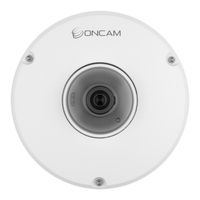
Oncam C-12 Series Installation And User Manual (225 pages)
Brand:
Oncam
| Category:
Security Camera
| Size: 24 MB
Table of Contents
Table of Contents
2
Legal and Warnings
3
Legal Considerations
3
Table 1 Port Pre - Configuration
6
Introduction
10
Camera Installation
11
Camera Configuration & Pre-Configuration
11
Placement and Orientation
12
Connection
13
Indoor Camera
13
Figure 1 Drilling Template
14
Figure 2 Opening of Camera Enclosure
14
Figure 3 Mounting of Camera Enclosure
14
Figure 4 Punch down Adapter
15
Figure 5 Identify Wiring Type for Punch down
15
Figure 6 Punch down Wires
16
Figure 7 Protective Cover Removal
16
Figure 8 Connecting of Camera Module
16
Figure 11 Protective Lens Cover Removal
17
Figure 10 Securing the Camera Module
17
Figure 9 Connecting of Ethernet Cable
17
Figure 12 Cover Twist
18
Figure 13 Drilling Hole
18
Figure 14 Feeding Ethernet Cable to the Hole
18
Figure 15 Connecting of RJ45 / Punch down
19
Figure 16 Snipping of Support Tabs for Punch down
19
Figure 17 Snipping of Support Tab for Ethernet Cable
19
Figure 20 Mount Screws Removal
20
Figure 19 Inserting of Grommet
20
Figure 18 Removal of Plug Using Pliers
20
Figure 21 Indoor Enclosure Opening
21
Figure 22 Inserting Punch down Adaptor
21
Figure 23 Punch down Ethernet Cable
21
Figure 24 Identify Wiring Type for Punch down
22
Figure 25 Punch down Wires
22
Figure 26 Inserting Rear Enclosure into Recessed Mount
23
Figure 27 Protective Cover Removal
23
Figure 28 Plug in RJ45 Cable
23
Figure 31 Protective Lens Cover Removal
24
Figure 29 Plugin of Camera Module into the Recessed Enclosure
24
Figure 30 Securing of Recessed Enclosure into the Ceiling
24
Figure 32 Clipping of Front Cover
25
Figure 33 Slot Alignment with LED
25
Figure 34 pendant Mount
25
Figure 35 Mounting Screws Removal
26
Figure 36 Opening of Camera Enclosure
26
Figure 37 Punch down Adaptor
26
Figure 39 Identify Wiring Type for Punch down
27
Figure 38 Punch down Ethernet Cable
27
Figure 40 Punch down Wires
28
Figure 41 Secure Camera Enclosure Onto the pendant Mount
28
Figure 42 Protective Cover Removal
28
Figure 43 Connecting Camera Using RJ5 / Punch down
29
Figure 44 Camera Image Alignment
29
Figure 45 Locking Screw
30
Figure 46 Protective Lens Cover Removal
30
Figure 47 Align and Close the Camera Enclosure
30
Figure 49 Remove Card Insert
31
Figure 48 Drilling Template
31
Figure 51 Opening of Camera Enclosure
32
Figure 52 Mounting of Camera Enclosure
32
Figure 50 Mount to Wall
32
Figure 53 Punch down Adapter
33
Figure 54 Identify Wiring Type for Punch down
33
Figure 55 Punch down Wires
34
Figure 56 Protective Cover Removal
34
Figure 57 Connecting of Camera Module
34
Figure 60 Protective Lens Cover Removal
35
Figure 58 Connecting of Ethernet Cable
35
Figure 59 Securing the Camera Module
35
Figure 61 Cover Twist
36
Figure 62 - Remove Label
36
Figure 63 - Hex Tool Unlocks
36
Outdoor Plus Camera
37
Figure 64 Loosen Captive Screws
37
Figure 65 Front Camera Enclosure Removal
37
Figure 68 Removal of Gland
38
Figure 67 Gland Identification
38
Figure 66 Drilling Template
38
Figure 69 Sealing of Cable
39
Figure 70 Gland into Rear Enclosure
39
Figure 71 Check Positioning
39
Figure 72 Gland Alignment
40
Figure 73 Rear Enclosure
40
Figure 74 Plugging RJ45 Connector to RJ45 Socket
40
Figure 77 Punch down Ethernet Cable
41
Figure 76 Insert Punch down Board
41
Figure 75 Removal of RJ45 Board
41
Figure 78 Identify Wiring Type for Punch down
42
Figure 79 Protective Film Removal
42
Figure 80 Protective Cover Removal
43
Figure 81 Camera Module Connection
43
Figure 82 Reattach Front Cover
43
Figure 83 Protective Cover Removal
44
Figure 84 Secure the Front Cover
44
Figure 85 Protective Cover Removal
44
Figure 88 Loosen Captive Screws
45
Figure 87 Removal of Mounting Screws
45
Figure 86 Ethernet Cable Onto the pendant Mount
45
Figure 89 Opening of Camera Enclosure
46
Figure 90 Gland Identification
46
Figure 91 Removal of Gland
46
Figure 92 Sealing of Cable
47
Figure 93 Gland into Rear Enclosure
47
Figure 94 Check Positioning
47
Figure 97 RJ45 Connector into RJ45 Socket
48
Figure 96 Secure Rear Enclosure to the pendant Mount
48
Figure 95 Gland Alignment
48
Figure 98 Removal of RJ45 Board
49
Figure 99 Insert Punch down Board
49
Figure 100 Punch down of Ethernet Cable
49
Figure 101 Identify Wiring Type for Punch down
50
Figure 102 Protective Film Removal
50
Figure 103 Protective Cover Removal
51
Figure 104 Camera Module
51
Figure 105 Camera Module Alignment
51
Figure 108 Secure Front Enclosure
52
Figure 106 Reattach the Front Cover
52
Figure 107 Protective Lens Cover
52
Figure 110 Camera after Installation
53
Figure 109 Protective Film
53
Figure 111 Undo the Locking Screw
54
Figure 112 Run Ethernet Cable
54
Figure 113 Screw to pendant
54
Figure 114 Adjust the Angle
55
Figure 115 Tighten the Locking Screw
55
Figure 116 - Screw on pendant Mount
55
Figure 119 Opening of Camera Enclosure
56
Figure 117 - Mounting Screws
56
Figure 118 Loosen Captive Screws
56
Figure 120 Gland Identification
57
Figure 121 Removal of Gland
57
Figure 122 Sealing of Cable
57
Figure 123 Gland into Rear Enclosure
58
Figure 124 Check Positioning
58
Figure 125 Gland Alignment
58
Figure 128 Removal of RJ45 Board
59
Figure 127 RJ45 Connector into RJ45 Socket
59
Figure 126 Secure Rear Enclosure to the pendant Mount
59
Figure 130 Punch down of Ethernet Cable
60
Figure 129 Insert Punch down Board
60
Figure 131 Identify Wiring Type for Punch down
61
Figure 132 Protective Film Removal
61
Figure 133 Protective Cover Removal
61
Figure 134 Camera Module
62
Figure 135 Reattach the Front Cover
62
Figure 136 Protective Lens Cover
62
Figure 139 Lock Angles
63
Figure 137 Secure Front Enclosure
63
Figure 138 Protective Film
63
Figure 140 Remove Mounting Screws
64
Figure 141 Align Rain Guard
64
Figure 142 Screw Rear Enclosure to pendant Mount
65
Figure 143 Align Rain Guard
65
Figure 144 - Insert Gland, Install to Surface
66
Figure 145 IO Entry Gland
66
Figure 148 Cable through Screw Terminals
67
Figure 147 Sealing the Cable Sheath
67
Figure 146 Multi - Core Cable
67
Figure 149 Cable Path to Screw Terminals
68
Figure 150 Alarm Output Signal
68
Figure 151 Alarm Input Signal
68
Figure 152 Audio Microphone
69
Figure 153 Audio Speaker
69
Figure 154 DC Power
69
Figure 155 Camera Module Removal
70
Figure 156 Camera Module Box
70
Figure 159 Remove Protective Film
71
Figure 158 Camera Module Box
71
Figure 157 Protective Cover Removal
71
Figure 160 Align Heater Module
72
Figure 161 Secure the Heater Module
72
Figure 162 Camera Module Box
72
Figure 163 Step 1 - Wall Mount Plate
73
Figure 164 Step 2 - Mounting Holes
73
Figure 165 Step 3 - Fixing Wall Mount into the Wall
73
Figure 168 Step 6 - Arm Body
74
Figure 166 Step 4 - Feeding Ethernet Cable through the Hook Plate
74
Figure 167 Step 5 - Hook Plate Placement
74
Figure 170 Step 8 - pendant Arm
75
Figure 169 Step 7 - Arm at Right Angle
75
SD Card Support
76
Figure 171 Microsd Card Slot
76
Figure 172 Inserting Microsd Card
76
Figure 174 Camera Front Cover
77
Figure 175 Retaining Front Screws Using Hex Tool
77
Figure 173 Microsd Card Insertion / Ejection
77
Uninstalling and Returns
77
Figure 176 Camera Module off the Rear
78
Figure 177 Undo Wall Mount Fix
78
Figure 178 Retaining Front Screws Using Hex Tool
79
Figure 179 Undo Retaining Tether
79
Figure 180 Remove Camera Module Screws Using Hex Tool
79
Camera Access
80
First Time Access - Discovery
80
Figure 181 Undo Wall Mounting
80
First Time Access - Set Primary Administrator Username and Password
82
Figure 182 CCT Discovery
82
Figure 183 Camera Web Interface, Set Password
83
Figure 184 CCT, Set Password
84
Figure 185 CCT Username and Password Setting
85
Figure 186 CCT Password Confirmation
86
Camera Configuration
87
Dashboard - Camera Web Interface
87
Figure 187 Dashboard Overview
87
Figure 188 Dashboard Overview Fullscreen
88
Network
90
Figure 189 Dashboard Logout
90
Figure 190 Network Configuration
91
Figure 191 Advanced Network Configuration
92
Figure 192 Advanced Network SNMP
93
Figure 193 Advanced Network EAP
95
Video/Audio Streaming
96
Figure 194 Media Profile Overview
97
Figure 195 Media Profiles, Camera Mode Change Request
98
Figure 196 Media Profiles, Camera Mode Changed
98
Figure 197 Media Profile Edit
100
Figure 198 Media Profile, New Profile Creation
101
Figure 199 Media Profile, Video Source Selection
102
Table 2 Characteristics and Capabilities of Encoders
102
Figure 200 Media Profile, Video Source Change Confirmation
105
Table 3 C-12 Video Resolutions Supported by Encoder and Video Source
106
Table 4 C-08 Video Resolutions Supported by Encoder and Video Source
107
Figure 201 Media Profile, Truedetail HDR Impact
108
Figure 202 Media Profile Bit Rate Control
112
Table 6 Encoder Bit Rate Level
113
Table 5 Encoder Bit Rate Level
113
Figure 203 Media Profile Streamlite Compression
115
Figure 204 Media Profile Video Multicast
117
Figure 205 Media Profile Audio
119
Figure 206 Media Profile Metadata
119
Figure 207 Media Profile Adjust Dewarped View
122
Figure 208 Media Profile Adjust Panoramic+ View
122
Figure 209 Media Profile Adjust Corridor+ View
125
Figure 210 Media Profile Adjust T Corridor+ View
126
Figure 211 Media Profile Adjust Vcam View
128
Figure 212 Media Profile Adjusted Vcam View
129
Figure 213 Image Setting Overview
130
Figure 214 Image Preference
132
Figure 215 WDR Image Setting
134
Figure 216 Camera Mounting
135
Figure 217 IR Cut Filter Mode
136
Figure 218 Color Space Mode
137
Figure 219 Overlays Overview
138
Figure 220 Overlay on Screen Caption
139
Figure 221 Overlays Privacy Region
140
Figure 222 Video / Audio Overlays Privacy Region
141
Figure 223 Video / Audio Overlays Privacy Region Overview
142
Figure 224 Global Streamlite Setting Colormap and Dynamic ROI
143
Figure 225 Global Streamlite Dynamic Gop Length Setting
145
Figure 226 Global Streamlite Dynamic FPS Reduction Setting
147
Figure 227 Global Streamlite Motion Setting
148
Figure 228 Global Audio Settings
149
Figure 229 Global Audio Settings, Audio Multicast
151
Recording
153
Figure 230 Multicast Summary Table
153
Figure 231 Recording Format Microsd Card
154
Figure 232 Recording Formatting Warning
154
Figure 233 Recording Formatting in Progress
155
Figure 234 Recording Formatting Complete
155
Figure 235 Recording Configuration Overview
156
Figure 236 Recording Create a Configuration
156
Table 7 Storage Requirements Estimation
157
Figure 237 Event Based Recording
159
Figure 238 Recording Configuration Editing
160
Figure 239 Recording Search
161
Events
163
Figure 240 Recording Search Result
163
Figure 241 Events Overview
164
Figure 242 Events Create New Rule
164
Figure 243 Events Trigger Action
170
Table 8 Events Trigger List
170
Figure 244 Event Recording Action
172
Motion / Analytics
174
Figure 245 Events Edit Rule
174
Figure 246 Motion Analytics Overview
175
Figure 247 Motion Analytics Create New
176
Figure 248 Motion Analytics Draw Region
177
Figure 249 Motion Analytics Edit Rules
183
Figure 250 Motion Analytics Global Settings
184
Users
185
Figure 251 Users Overview
185
Figure 252 New User Creation
186
Figure 253 User Summary Table Update
188
Figure 254 User Editing Options
188
Figure 256 Device Information Overview
189
Figure 255 Users, Delete Account Confirmation
189
Device
189
Figure 257 Device Information EVO-12 ONVIF Emulation
191
Figure 258 Date / Time Overview
192
Figure 259 Date / Time Manual Setting
193
Figure 260 Date / Time NTP Network Setting
194
Figure 261 Date / Time NTP Save Setting
194
Figure 262 Maintenance Support Reboot
195
Figure 263 CCT Maintenance Support Reboot
196
Figure 264 CCT Maintenance Support Reboot Progress Status
196
Figure 265 Maintenance Support Reset
198
Figure 266 CCT Maintenance Support Reset
198
Figure 267 Maintenance and Support Backup
200
Table 9 Status LED
201
Figure 268 Maintenance Support Status LED
202
Figure 269 Firmware Update
203
Figure 270 Firmware Update Progress Display
204
Figure 271 CCT Firmware Update Multiple Cameras
204
Figure 272 CCT Firmware Update Multiple Cameras Progress Bars
205
Figure 273 License Overview
207
Figure 274 Download Root CA
210
Figure 275 Install Root CA Certificate
210
Peripherals
211
Figure 276 Peripheral Input / Output Overview
212
Figure 277 Peripheral Edit Input
213
Table 10 Plus Module Alarm Input
213
Figure 278 Peripheral Edit Alarm Output
214
Table 11 Plus Module Alarm Output
214
Figure 279 Peripheral Edit LED Output
216
Technical Support
218
Appendix B List of Figures
220
Advertisement
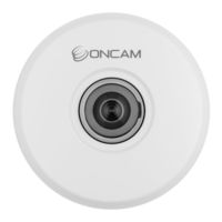
Oncam C-12 Series Installation & User Manual (11 pages)
Brand:
Oncam
| Category:
Security Camera
| Size: 3 MB
Table of Contents
Table of Contents
2
1 Camera Access
3
First Time Access - Discovery
3
First Time Access - Set Primary Administrator Username and Password
4
2 Camera Configuration
9
Dashboard - Camera Web Interface
9
Advertisement
Related Products
Oncam C-12 Outdoor Plus
Oncam C-08 Outdoor
Oncam C Series
Oncam EVO-180-WED
Oncam Evolution 12 Series
Oncam Categories
Security Camera
IP Camera
Camera Accessories
Outdoor Camera
Digital Camera
More Oncam Manuals
Login
Sign In
OR
Sign in with Facebook
Sign in with Google
Upload manual
Upload from disk
Upload from URL