OMRON V700 series Manuals
Manuals and User Guides for OMRON V700 series. We have 4 OMRON V700 series manuals available for free PDF download: Operation Manual, Datasheet

Omron V700 series Operation Manual (168 pages)
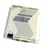
Electromagnetic Inductive RFID System
Brand: Omron
|
Category: Rfid Systems
|
Size: 1.64 MB
Table of Contents
Advertisement
Omron V700 series Operation Manual (142 pages)
Electromagnetic Inductive RFID System
Table of Contents
Advertisement

OMRON V700 series Datasheet (10 pages)
Electromagnetic RFID System
Brand: OMRON
|
Category: Controller
|
Size: 1.43 MB
Table of Contents
Advertisement