Sign In
Upload
Manuals
Brands
Omron Manuals
Touch terminals
NS15-V2 Series
Omron NS15-V2 Series Manuals
Manuals and User Guides for Omron NS15-V2 Series. We have
2
Omron NS15-V2 Series manuals available for free PDF download: Setup Manual, Manual
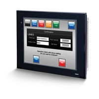
OMRON NS15-V2 Series Setup Manual (334 pages)
NS-Series Programmable Terminals
Brand:
OMRON
| Category:
Touch terminals
| Size: 7 MB
Table of Contents
Table of Contents
4
About this Manual
9
Related Manuals
10
Terminology
11
Introduction
12
Overview
23
Section 1 Overview
23
Types, and Communications Methods.
24
This Section Provides an Overview of the NS-Series Pts, Including Functions, Features, Connection
24
NS-Series PT Functions and Operation
24
PT Functions for FA Manufacturing Sites
24
NS-Series PT Operating System
25
Communications with the Host
27
What Is an NT Link
28
Ethernet
28
Controller Link
28
Host Link
28
Connecting to a Temperature Controller
28
Memory Link Connections
29
Communicating with Other Devices
29
Ethernet/Ip
29
System Configuration
30
Supported Peripheral Devices
30
Procedure for Running NS-Series Pts
32
Before Connecting
35
Section 2 before Connecting
35
Connecting the Host
36
Communications Types and Connection Methods
36
Part Names and Functions
42
Installing the PT and Connecting Peripheral Devices
55
Installing the PT
57
Installation Environment
57
Installing RS-232C/RS-422A Converters
58
Mounting the PT to the Control Panel
58
Connecting the Power Supply
60
Wiring the Ground Wire
61
Peripheral Device Connection Limitations
62
Starting the PT
63
Operation at Startup
63
Starting the PT for the First Time
65
Connecting the CX-Designer
67
Connecting Via RS-232C or Ethernet
67
Connecting Via USB
67
Connecting Via a Modem
69
Connecting to Bar Code Readers
70
Connection Methods
70
Setting Bar Code Readers
71
Data Format
72
Bar Code Input
72
Connecting to Printers
73
Connecting to a Printer Compatible with ESC/P Raster and BJ Raster
73
Connecting a Pictbridge-Compatible Printer
74
Using Memory Cards
76
Installation
77
Replacing the System Program
78
Transferring Data with Memory Cards
79
3-7 Installing the Video Input Unit
86
Installing the Video Input Unit
86
Video Input Unit Components
86
Nomenclature and Functions
86
Installation Method for Video Input Unit
87
Connecting to Video Input Connectors
92
3-8 Installing the Controller Link Interface Unit
98
Installing the Controller Link Interface Unit
98
Nomenclature and Functions
98
Installation Method for Controller Link Interface Unit
101
Wiring
108
Connecting a Monitor
114
External Brightness Adjustment
115
RS-232C/RS-422A Selector DIP Switch
116
Connecting the Host to Serial Port
117
Connection).
118
On Connecting to Another Company's PLC, Refer to the Host Connection Manual (Multivendor
118
Communications, Refer to the Host Connection Manual (Temp. Control, Memlink). for Details
118
1:1 Host Connection
118
Connection Methods
118
Unit Setting Methods
120
1:N Host Connection
123
Connection Methods
123
Unit Setting Methods
123
High-Speed 1:N NT Link
134
Unit Setting Methods
135
Recommended Connector Cables
143
Connecting to Host Via Ethernet or Controller Link
145
Connecting to Host Via Ethernet
146
Host Types and Settings
147
Connecting to the Host Using Controller Link
161
What Is a Controller Link Network
161
Data Links
162
Troubleshooting Using Indicators
167
Connecting to Host Via Ethernet/Ip
170
What Is Ethernet/Ip
170
Setting Individual Units
171
System Menu Operations
175
Operating Modes and System Menu
177
Mode Configuration
177
System Menu Configuration
177
Overview of Menu Items
178
Using the System Menu
181
Initializing and Saving Data and Removing the Memory Card
184
Screen Data Area Format
185
Initializing or Saving the Alarm/Event History
186
Initializing and Saving Data Log
188
Initializing and Saving the Operation Log
189
Initializing and Saving the Error Log
191
Language Selection
192
Removing the Memory Card
193
Initializing Internal Holding Memories ($HB/$HW)
194
PT Settings
195
Start-Up Wait Time
197
Screen Saver
198
Key Press Sound
199
Buzzer Sound
199
Backlight Brightness
200
Calendar Check
201
Printer Type
202
Printing Mode
202
Orientation
203
Changing Values in Device Monitor Setting
203
Contrast (NS5-SQ@@/NS5-MQ@@ Only)
203
CJK Han Unification Priority
204
Alarm Monitor Registration Procedure
204
(NS15/12/10/8 Only)
204
Setting the Tag Update Notification Message
205
Time to Switch to System Menu (NS12, NS10, NS8, or NS5)
205
Double-Touch Interval (NS15 Only)
206
Analog RGB Output (NS15 Only)
206
Project Settings
207
Project Title
207
Number of Labels
208
Initial Screen
208
Initial Label
208
Alarm/Event History Recording Method
208
Data Log Recording Method
208
Operation Log Recording Method
209
Error Log Recording Method
209
System Memory
209
Setting Passwords
210
Changing the Password
210
Setting the Password Function
211
Communications Settings
213
Communications Conditions
213
Setting 1:1 NT Link
215
Setting High-Speed 1:N NT Links (Standard, High-Speed)
216
Setting Ethernet
216
Setting the Controller Link Network
219
Setting Bar Code Readers
220
Modem Settings
221
Screen Data Check
222
Special Screens
223
Alarm History
224
Operation Log
225
Error Log
226
Device Monitor
227
Communication Test
229
Video Configuration
231
USB Device List
233
Display Capture Data
234
Memory Card Transfers
235
External Application Startup
237
Version Display
238
PLC Data Trace (NS15, NS12, NS10, and NS8 Only)
238
Hardware Check
240
LCD Check
240
Touch Switch Check
241
Touch Panel Calibration (NS15 Only)
241
Starting Operations
242
Verifying Tags
244
Maintenance and Troubleshooting
247
Maintenance
248
Replacing the Battery
248
Inspection and Cleaning
250
Troubleshooting and Maintenance
252
Requesting a Replacement PT
260
Appendices
261
Appendix 1 Specifications
263
A-1-1 General Specifications
263
A-1-2 Characteristics
265
Appendix 1 Specifications
267
A-1-3 Communications Specifications
268
Appendix 2 Dimensions
272
Appendix 3 Using NS-AL002 Converters
281
A-3-1 Dimensions
281
A-3-2 Mounting and Removing
282
A-3-3 Specifications
282
A-3-4 DIP Switch Settings
283
A-3-5 Pin Arrangement
284
A-3-6 Handling the Shield on RS-422A/485 Cables
285
A-3-7 Connection Example
288
Appendix 4 Using NT-AL001 Converters
289
A-4-1 Dimensions
289
A-4-2 Methods for Mounting and Removal
289
A-4-3 Specifications
291
A-4-4 DIP Switch Settings
292
A-4-5 Pin Arrangement
293
A-4-6 Block Diagram
294
Appendix 5 Preparing Connecting Cables
295
A-5-1 Cable Preparation
295
A-5-2 Soldering
296
A-5-3 Hood Assembly
296
A-5-4 Preparing Connecting Cables for Host Connection
297
Appendix 6 Preparing Cables for Computer Connection
301
A-6-1 Connecting Cable Assembly
301
Appendix 7 Preparing Connecting Cables for Bar Code Readers
303
Appendix 8 Standard Models
304
Appendix 9 List of Optional Products
319
A-9-1 Anti-Reflection Sheets: NS15-KBA04, NS12-KBA04, NS7-KBA04, NT30-KBA04
319
Appendix 9 List of Optional Products
320
A-9-2 Protective Covers: NS12-KBA05(N), NS7-KBA05(N), NT31C-KBA05(N)
320
Nt30-Kba04
321
A-9-3 NT30-KBA01 Chemical-Resistant Cover
321
A-9-4 Replacement Battery: CJ1W-BAT01
321
A-9-5 Recommended Memory Cards
322
A-9-6 NS-CLK21 Controller Link Interface Unit
322
A-9-7 NS-CA001/CA002 Video Input Unit
322
A-9-8 Attachments: NS12-ATT01(B)/NS12-ATT02/NS8-ATT01/ NS8-ATT02
322
A-9-9 NS-USBEXT-1M USB Relay Cable
323
Appendix 10 System Memory List
324
Appendix 11 Differences between "-V1"/"-V2" Models and Other Models
327
Appendix 12 NS5 System Menu
329
Advertisement
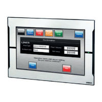
Omron NS15-V2 Series Manual (100 pages)
Industrial PC Platform
Brand:
Omron
| Category:
Industrial PC
| Size: 3 MB
Table of Contents
Intended Audience
3
Applicable Products and Replacements
3
Sections in this Manual
5
Table of Contents
6
Manual Information
9
Page Structure
9
Special Information
10
Terms and Conditions Agreement
11
Warranty, Limitations of Liability
11
Application Considerations
12
Disclaimers
13
Safety Precautions
14
Precautions for Safe Use
15
Precautions for Correct Use
16
Regulations and Standards
17
Conformance to EU Directives
17
Conformance to UL and CSA Standards
17
Software Licenses and Copyrights
18
Related Manuals
19
NYE Manuals
19
Related Products Manuals
20
Terminology and Abbreviations
21
Industrial PC Platform
21
Hardware
21
Software
22
Revision History
23
Overview
25
Intended Use
26
Product Configuration
27
Overall Conversion Procedure
28
Hardware
31
Warning - Information Not Complete
32
Layers and Components
33
Base Layer NYE
34
Display Layer NYE
35
Cfast Card Slot
36
Spare Parts
37
Battery
37
Optional Hardware
38
Cfast Cards
38
Power Supply
38
Ups
39
Specifications
41
Warning - Information Not Complete
42
General Specifications
43
Dimensions and Weight
43
General Electrical Specifications
45
Power Consumption Specifications
46
Power Supply Specifications
47
Storage Device Specifications
47
USB Connector Specifications
48
Display Specifications
49
Minimize LCD Image Retention
50
Environmental Specifications
51
Operation Environment Specifications
51
Temperature and Humidity Specifications
52
Installation
55
Warning - Information Not Complete
56
Install Options
57
No Options
57
Mount
58
Product Orientation
58
Panel Mount Procedure
59
Temperature
63
Wire
64
Ground
64
DC Power Supply
65
Connect
66
Connection Procedure
66
Initial Power on
67
Initial Power on Procedure
67
Windows Startup First Time
69
Auto Power on
70
Power off
71
Conversion Procedures
73
Hardware Conversion
74
Software Conversion
75
Upgrade an NS Project to Version 8.1
76
Convert Model of an NS Project to NS-Runtime
77
Modify the NS-Runtime Project
79
Modify Object Dimensions, Fonts and Screen Resolution
89
Modify Screen Resolution for an NS-Runtime Project
90
Correct Screen Resolution Issues
91
Create Backup and Repair Data
93
Advertisement
Related Products
OMRON NS15-TX Series
Omron NS15-TX01*-V2
Omron NS15-TX01S-V2
Omron NS10-V2
Omron NS12-V2
OMRON NS10-TV Series
OMRON NS12-TS00 Series
OMRON NS12-TS01 Series
Omron NS12-TS01 V1 Series
Omron NS12-TV00*-V1
Omron Categories
Blood Pressure Monitor
Controller
Accessories
Switch
Inverter
More Omron Manuals
Login
Sign In
OR
Sign in with Facebook
Sign in with Google
Upload manual
Upload from disk
Upload from URL